Instruo Lion User manual
lìon
Matrix Mixer
User Manual


3
Description
The Instruō lìon is a 6x6 matrix mixer with a pin style interface similar
to those found on iconic modular synthesizers of the 1970s. Its
applications range from signal routing and effect insert functionality to
true summing with cascaded attenuation capabilities.
Live patching made easy with the use of the included pin and
insert cables.
Need to patch to a new destination? Simply pin your patch on the fly.
Centralise your I/O network with lìon.
Features
• 6x6 pin-style matrix mixer
• Send & return insert capabilities
• True summing
• Passive multiple functionality
• Cascaded attenuation through channels 3-6
• Includes 10 pin cables
• Includes 2 insert cables (black = send, gold = return)
Insert Cable
Pin Cable

4
Installation
• Confirm that the Eurorack synthesizer system is powered off.
• Locate 16 HP of space in your Eurorack synthesizer case.
• Connect the 10 pin side of the IDC power cable to the 2x5 pin
header on the back of the module, confirming that the red stripe on
the power cable is connected to -12V.
• Connect the 16 pin side of the IDC power cable to the 2x8 pin
header on your Eurorack power supply, confirming that the red
stripe on the power cable is connected to -12V.
• Mount the Instruō lìon in your Eurorack synthesizer case.
• Power your Eurorack synthesizer system on.
Note:
This module has reverse polarity protection.
Inverted installation of the power cable will not damage the module.
Specifications
• Width: 16 HP
• Depth: 27mm
• +12V: 30mA
• -12V: 30mA

5
lìon
IN
OUT
αβγδε
ζ
6
5
4
3
2
1
lìon |ljD | noun (networking) an open-meshed form, twisted, knotted,
or woven together at regular intervals a group of communication
stations operating under unified control
Key
1. Inputs
2. Outputs
3. Patch Points
6
When referring to matrix mixers, it's a good idea to refer to the different
Patch Points by rows and columns. For instance, talking about [1, alpha]
would refer to the Patch Point on the top row and first column (top left).
[4, gamma] would refer to the Patch Point on the fourth row and
third column.
Inputs: lìon includes six DC coupled inputs for audio and control voltage
signals, labeled 1, 2, 3, 4, 5, and 6.
Outputs: lìon includes six DC coupled outputs for audio and control
voltage signals, labeled alpha, beta, gamma, delta, epsilon, and zeta.
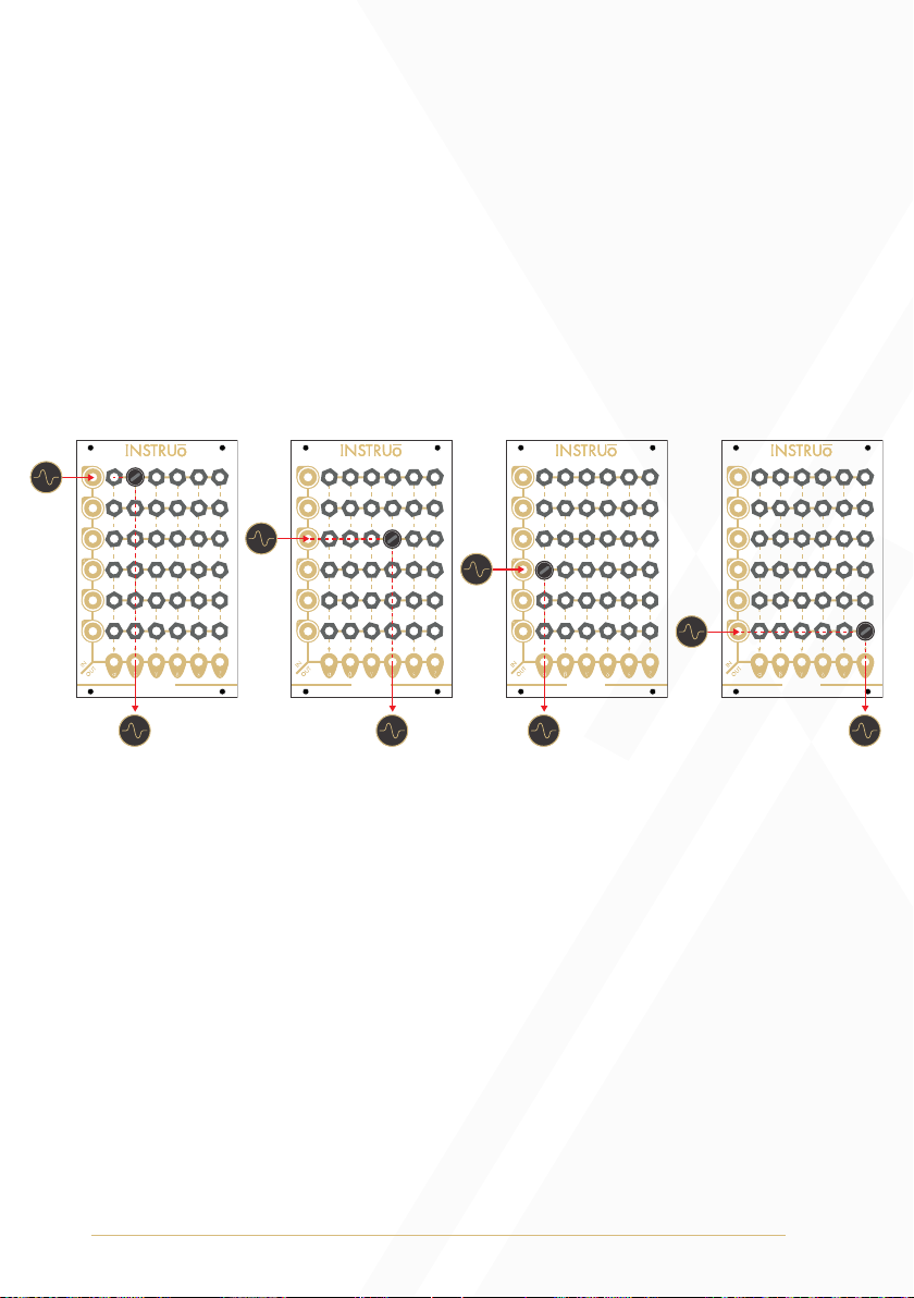
• The alpha and beta Outputs will always output summed signals at
unity gain.
• The gamma, delta, epsilon, and zeta outputs mix at unity gain from
pinned sources, but will also sum the signal from the output directly
to their left (if that output is unpatched). This throughput has a gain
reduction of 1/3. Multiple Pin Cables in the same row will add gain
to the input signal.
lìon lìon lìon lìon
[1, beta] [3, delta] [4, alpha] [6, zeta]
7
Multiple Pin Cables in the same row will add gain to the input
signal. For example, if an input signal is present at Input 1, and a
Pin Cable is inserted to [1, alpha] the signal at the alpha Output
and beta Output will be unity gain. At the gamma Output, the
signal will be attenuated by 1/3. At the delta Output, another
1/3, cascading attenuation as the channel outputs are summed.
Normal
Sleeve
Tip Attenuation

8
• Similarly, if an input signal is present at Input 1 and a Pin Cable
is inserted to [1, zeta] the signal at the zeta Output be unity gain.
Adding another Pin Cable at [1, epsilon] will increase the signal's
gain by 2/3. Adding yet another Pin Cable at [1, delta] will
increase the signal's gain by another 2/3, so on and so forth,
cascading gain as the channel outputs are summed.
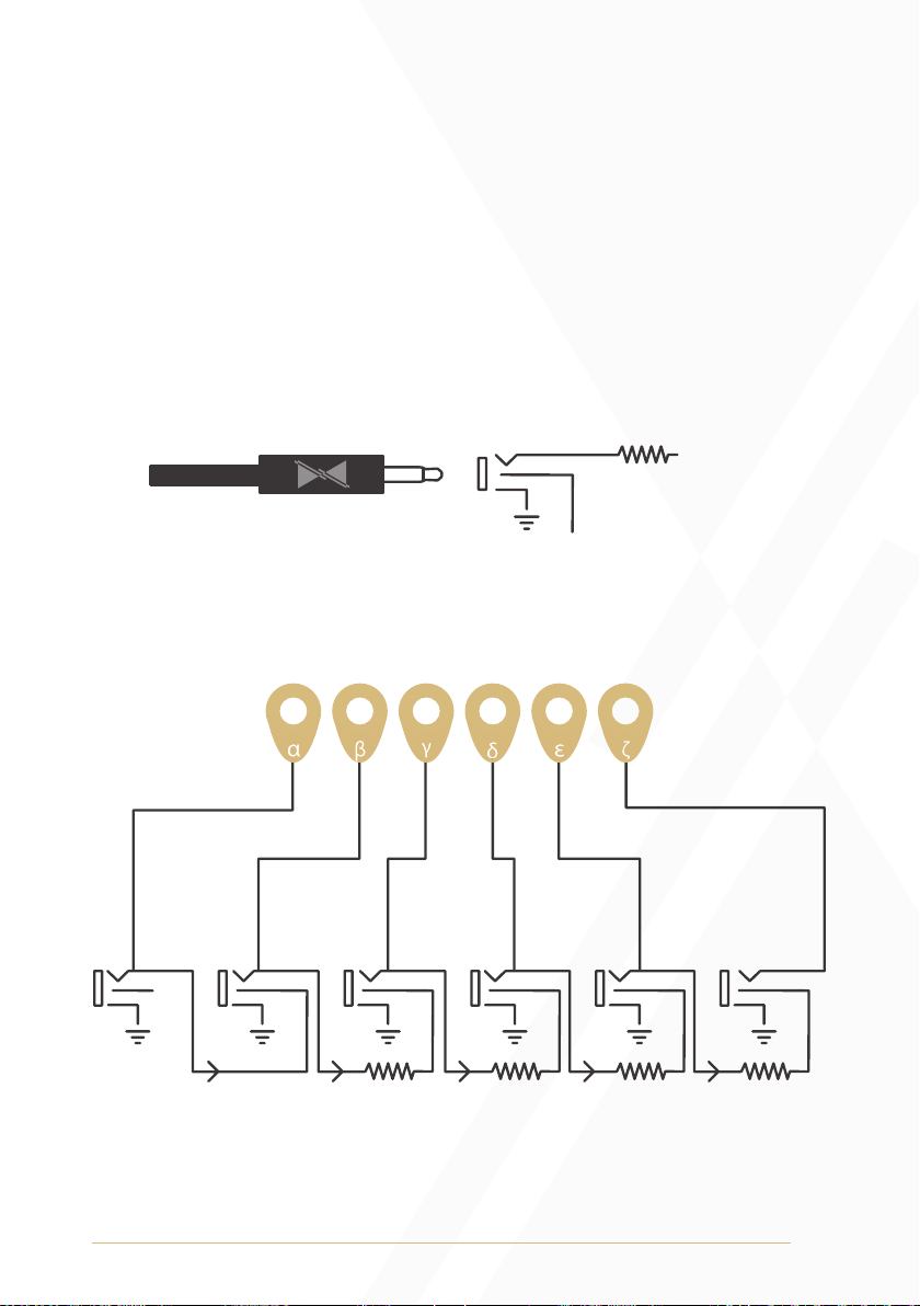
Patch Points: The Patch Points are used for signal routing and effect
insert functionality.
• Patching out from the Patch Points with a standard mono patch
cable will serve as a passive multiple from the signal at the input.
Output
Input Pin Cables
9
Patch Examples
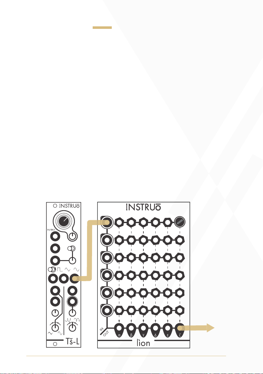
Mixing:
• Connect different signals to any of the Inputs and monitor from the
zeta Output.
• Insert Pin Cables to the Patch Points on any of the
corresponding rows.
• Different levels of attenuation are applied based on which
Patch Points you insert Pin Cables into.
• Adding multiple Pin Cables in a row will add gain to the
input signal.
For instance, with a signal present at Input 1, inserting a Pin Cable to
[1,zeta] will pass the signal to the zeta Output at unity gain. As the Pin
Cable is moved to the left, the signal will attenuate the signal by 1/3
with each consecutive Patch Point with the exception of the first two
Patch Points which apply the same amount of attenuation.
Output Signal

10
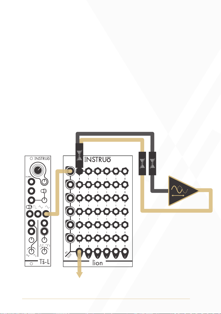
Cross Modulation:
• Insert three audio signals from one oscillator to Inputs 1-3 of lìon.
• Insert another three audio signals from a second oscillatior to
Inputs 4-6 of lìon.
• Monitor from the gamma Output.
• Connect the alpha and beta Outputs to two inputs on the second
oscillator (FM and wavefold amount, for instance).
• Connect the delta, epsilon, and zeta Outputs to three inputs on the
first oscillatior.
• Any Patch Point on the gamma column will pass audio to the output.
• Any other Patch Point will connect the audio signals from the
oscillators to modulation inputs on the opposing oscillators.
Output Signal
11
Effect Insert:
• Connect an audio signal to Input 1 and monitor from the
alpha Output.
• Patch an Insert Cable to [1,alpha].
• Connect the black end of the Insert Cable (send) to the input of the
desired effect.
• Connect the output of the desired effect to the gold end of the Insert
Cable (return).
• This can be done on any Input and Output as long as the
Patch Point connects them.
Monitor Output
Chorus
12
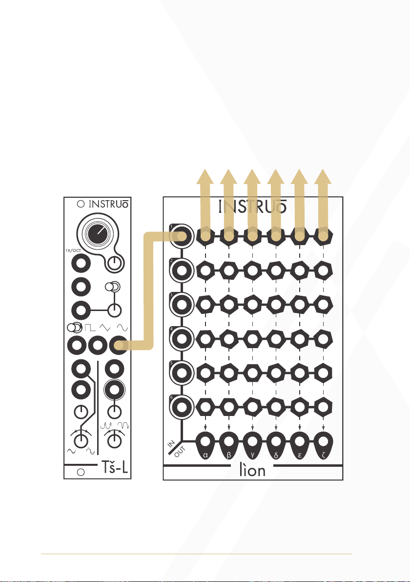
Passive Mult:
• Patching out from the Patch Points with a standard mono patch
cable will serve as a passive multiple from the signal at the input
• Each row serves as a 1 to 6 passive mult.
Output Signals

13
Basic Feedback:
• Connect an audio signal to Input 1 and monitor from the
zeta Output.
• Insert a Pin Cable into [6, zeta].
• Connect a patch cable from alpha Output back into Input 6.
• Patch an Insert Cable to [6, alpha].
• Connect the black end of the Insert Cable (send) to the input of
a VCA.
• Connect the output of the VCA to the gold end of the
Insert Cable (return), this will create a VCA controlled
feedback loop.
• In order to introduce your audio source into the loop, insert a
Pin Cable into [1, alpha].
Monitor Output

14
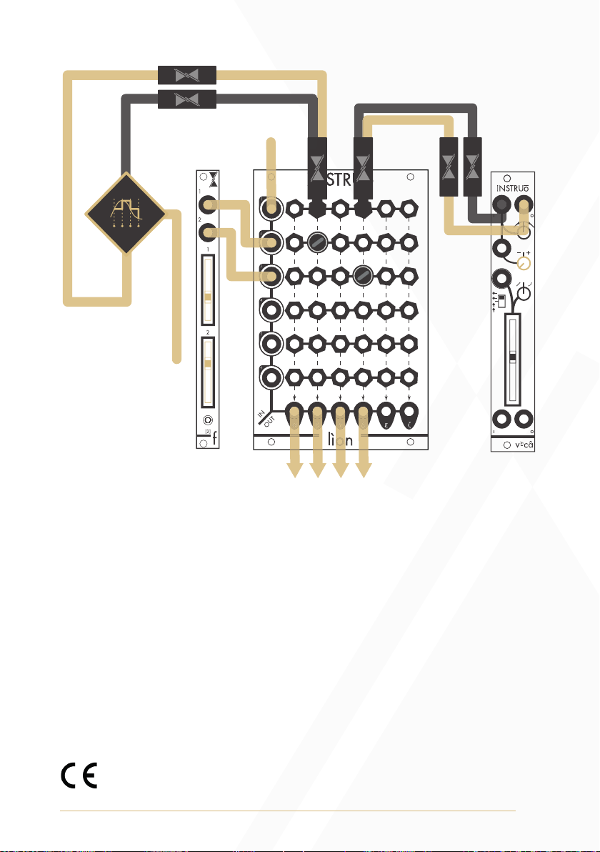
1V/Oct Routing:
Variations of the original 1V/Oct signal can be created by summing the
original signal with the offset values of 2[f], inverting the original signal
using the first channel of vincâ, sampling the original signal with the
sample and hold.
• Connect a 1V/Oct signal to Input 1
• Connect 2[f] to Input 2 and Input 3
• Patch an Insert Cable to [1, beta]
• Connect the black end of the Insert Cable (send) to the input of
a sample and hold.
• Connect the output of the sample and hold to the gold end of the
Insert Cable (return).
• Patch an Insert Cable to [1, delta].
• Connect the black end of the second Insert Cable (send) to the input
of channel one of a vincâ.
• Connect the output of channel one of the vincâ to the gold end of the
second Insert Cable (return).
• Insert Pin Cables to [2, beta] and [3,delta] .
• Send alpha, beta, gamma and delta Outputs to different
1V/Oct inputs.
(Diagram on next page)
15
This device meets the requirements of the following standards: EN55032,
EN55103-2, EN61000-3-2, EN61000-3-3, EN62311.
Module Design: Aimo Scampa
Manual Author: Collin Russell
Manual Design: Dominic D’Sylva
1V/Oct Signals
1V/Oct Signal
Sample and Hold
Trigger Signal
Table of contents


