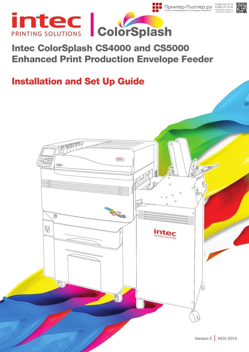
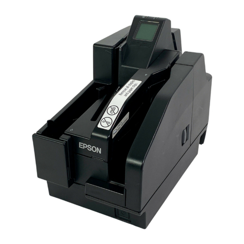
Intec CS4000 User manual

4
Basic Device
Operations
Preparing the printer
to print
2
Setting Up
Before
Use
User's Manual
Basic
C911dn
C931dn
C941dn
ES9411dn
ES9431dn
ES9541dn ○This manual contains cautions on how to use this product safety.
Before you use this product, please make sure that you read this manual.
○Carefully store this manual close to hand so.
1
Appendix
Index
3Printing

- 2 - - 3 -
Manual Con guration
The following user manuals are enclosed with the product.
The e-manual is stored on the "Software DVD-ROM".
Basic (This manual)
Preparing the printer to print
Try using various functions
Read for any points that are not understood, or for maintenance
Using CS5000
This guide describes the precautions for safe
use of the device. Make sure to read before use.
Further, basic uses from the device installation
methods to initial printing are also explained.
The device functions are described in the
appendix.
Read these guides as necessary
Advanced
2
Step
This guide explains the various paper print methods
and how to use useful functions. Read to optimize the
printing environment or to adjust the color, etc., using
the enclosed utility software.
Further, this guide also explains the items that can be
set from the control panel, and the network settings.
Troubleshooting/Daily
Maintenance Manual
This manual explains the procedures for paper jams, and
troubleshooting method if an error message is displayed. This
manual also explains daily maintenance such as now to replace
consumables and maintenance units, and cleaning, etc.
•Troubleshooting
•Maintenance
•Consumables, maintenance products,
options, color management server,
etc.
・E-format
・E-format
・E-format
Read this first
Easy Guide (Set-up Guide)
Opening the box and installing the printer
1
Step
This guide uses illustrations to explain the
methods from opening the box to installation.
For the advanced setup guide, see the "Basic".
・Pamphlet
•Checking the product
•Parts nomenclature and functions
•Using the device to its fullest
•Installing the device
•Turning ON and OFF the power supply
•Test printing using the printer only
•Connecting to a PC
•Paper
•Printing
•Paper ejection
•Setting Power Save mode
•Setting auto power OFF
•Checking the print quantity,
consumables, remaining maintenance
unit quantity, and remaining service life
•Cancelling a print job
•Adding printers using LPD protocols
(TCP/IP)
•Table of control panel menu items
•Basic Windows procedures
•Printer specifications
•Useful print functions
•Adjusting the color
•Using utility software
•Network settings
•
Checking and changing printer settings
using the control panel
Separate Volume Spot Color Guide
This guide explains how to set up the Spot
Color kit and check the printer drivers, and
how to print using Spot Color. Make sure to
read before use.
•Setting the Spot Color kit
•Control panel explanation
•Checking the printer drivers
•Table of printer driver functions
•Printing on color paper
•Printing on transparent film
•Specifying and printing Spot Color
toner using the applications
•Fine-tuning white
•Switching Spot Color kits
・E-format
4
BasicDevice
Operations
2
SettingUp
Before
use
User'sManual
Basic
○Thismanual contains cautions on how to use this product safety.
Beforeyou use this product, please makesure that you read this manual.
○Carefullystorethis manual close to handso.
1
Appendix
Index
3
Printing
Readfor any pointsthat
arenot understood,or
formaintenance
1
Troubleshooting
2
Maintenance
Index
User’sManual
Troubleshooting/Daily
Maintenance Manual
Storethis manual carefully close to hand so it can be viewed at any time.
User'sManual
Separate Volume Spot Color Guide
About the Enclosed "Software DVD-ROM"
When the "software DVD-ROM" enclosed with the device is placed in the DVD-ROM drive, the following
menu screen will be displayed.
Memo
This example uses the Windows screens.
If using a Macintosh, double-click the [Intec] icon.
Describes the selected
printer and PC connection
type.
Click here to install the standard
printer drivers.
You can add and select printer
drivers.
To learn the easy device functions
and various settings, see the PDF
manual from here. *2
You can install and set the device
utility software.
Select the printer
model.
Select the device and
PC connection method.
You can register as a
user from the Intec
homepage. *1
Close the "Software
DVD-ROM".
*1: Access is only possible using an internet-enabled environment.
*2: To view the PDF manual, Adobe Reader/Adobe Acrobat Reader is required.

- 4 - - 5 -
Reading the Manual
Symbols
Note
These are cautions and restrictions for the correct operation of the device. Make sure to read to avoid misoperation.
Memo
Knowledge of the information before using the device is useful and can act as a reference. Reading is recommended.
Reference
These are the reference pages. Read to learn detailed information and relevant information.
DANGER
Mishandling due to ignoring this display may cause death or serious injury.
WARNING
Mishandling due to ignoring this display may cause death or serious injury.
CAUTION
Mishandling due to ignoring this display may cause personal injury.
Keys, Buttons, and Symbols
This chapter described the following keys, buttons, and symbols.
Inscription Explanation
[ ] button/key
The control panel buttons and 10-key pad are described below.
E.g.:
[OK] button [BACK] button
[Fn] key [CLEAR] key
Indicates your PC keyboard.
[ ]
Describes the menu name on the liquid crystal panel.
Describes the PC menus, windows, and dialog box names.
" "
Describes the messages and input text displayed in the liquid crystal
panel.
Describes the le and screen names on the PC.
Describes the reference title.
> Describes the menu level of the device or PC.
Illustrations
The device illustrations used herein show the
CS5000 model unless otherwise specied.
Illustrations may differ from the actual product.
Screens
The images of the control panel and PC used
herein are examples. The images may differ
from actual products and screens.

- 6 - - 7 -
Inscriptions
The following inscriptions are used in this manual.
CS4000
CS5000
Microsoft®Windows®7 64-bit Edition operating system →Windows 7 (64bit version)
Microsoft®Windows®7 operating system →Windows 7
Mac OS X10.5 or later →Mac OS X
The manuals enclosed with the printer use as examples Windows 7 in the case of Windows, and OS X
10.8 in the case of Mac OS X unless otherwise specied.
Depending on the OS and model used, descriptions in this manual may differ.
About the Product Warranty
Every effort has been made to ensure that the information in this document is complete, accurate,
and up-to-date. The manufacturer assumes no responsibility for the results of errors beyond its
control. The manufacturer also cannot guarantee that changes in software and equipment made by
other manufacturers and referred to in this guide will not affect the applicability of the information
in it. Mention of software products manufactured by other companies does not necessarily constitute
endorsement by the manufacturer.
While all reasonable efforts have been made to make this document as accurate and helpful as possible,
we make no warranty of any kind, expressed or implied, as to the accuracy or completeness of the
information contained herein.
All rights are reserved by Intec Printing Solutions. You must not copy, transfer, translate, etc. the
content herein without authorization. You must obtain written permission from Intec Printing Solutions
before doing any of the above.
© 2013 Intec Printing Solutions Ltd
Energy Star is a trademark of the United States Environmental Protection Agency.
Microsoft, Windows, Windows Server and Windows Vista are registered trademarks of Microsoft
Corporation.
Apple, Macintosh, Rosetta, Mac and Mac OS are registered trademarks of Apple Inc.
Other product names and brand names are registered trademarks or trademarks of their proprietors.
As an ENERGY STAR ® Program Participant, the manufacturer has determined that this
product meets the ENERGY STAR guidelines for energy efciency.
This product complies with the requirements of the Council Directives 2004/ 108/EC (EMC),
2006/95/EC (LVD),1999/5/EC (R&TTE), 2009/125/EC (ErP) and 2011/65/EU(RoHS), as
amended where applicable, on the approximation of the laws of the member states relating
to Electromagnetic Compatibility, Low Voltage, Radio & Telecommunications Terminal
Equipment, Energy related Products and Restriction on the use of certain Hazardous
Substances in electrical and electronic equipment.
The following cables were used to evaluate this product to achieve EMC directive
2004/108/EC compliance and congurations other than this may affect that compliance.
cable type length
(meters) core shield
Power 1.8 7 7
USB 5.0 7 3
LAN 15.0 7 7

- 8 - - 9 -
For Your Safety
Read the User’s Manual for your safety before using the product.
Cautions related to safety
WARNING
A warning provides additional information which, if ignored, may result in a risk of personal injury.
CAUTION
A caution provides additional information which, if ignored, may result in equipment malfunction
or damage.
General cautions
WARNING
Do not touch the safety
switch inside the machine.
Doing so may cause electric
shock when high voltage
occurs. In addition, gears can
rotate, which may result in
personal injury.
Do not use an inammable
spray near the machine.
Doing so may cause re
since there is an area heating
up within the machine.
Pull the power plug out of
the socket and contact with
a customer’s service center
when the cover is unusually
hot, smIntecng, giving off
questionable odour, or making a
strange noise.
Failure to do so may cause re.
Pull the power plug out of
the socket and contact with
a customer’s service center
when a liquid such as water
enters in the internal parts of
the machine.
Failure to do so may cause
re.
Pull the power plug out of the
socket and remove foreign
materials such as clips when
they fall inside the machine.
Failure to do so may cause
electric shock and/or re
leading to personal injuries.
Do not operate and/or
disassemble the machine
other than that directed in
User's Manual.
Doing so may cause electric
shock and/or re leading to
personal injuries.
Unplug the power cord and
contact with a customer’s
service center if the machine
is dropped or the cover is
damaged.
Failure to do so may cause
electric shock and/or re
leading to personal injuries.
Unplug the power cord
periodically to clean plug
blades and root section
between the blades. If the
power plug remains inserted
for a long time, the root
section will get dusty, and
the plug may be shorted out,
which may cause re.
Do not clean spilled toner with
a vacuum cleaner.
If cleaning spilled toner with a
vacuum cleaner, it may catch
re due to the sparks from
electric contact.
Toner spilled on the oor
should be wiped off with wet
cloth.
Do not insert materials in a
vent hole.
Doing so may cause electric
shock and/or re leading to
personal injuries.
Do not put a cup with liquids
such as water on the machine.
Doing so may cause electric
shock and/or re leading to
personal injuries.
Do not touch the fuser and
other parts when opening the
cover of the machine.
Doing so may cause burns.
Do not throw toner cartridges
and image drum cartridges
into re. Doing so may cause
dust explosion leading to
burns.
Do not use a power cord, a
cable, or a ground wire other
than those that are indicated
in User's Manual.
Doing so may cause re.
The operation of using UPS
(uninterruptible power source)
or inverters is not guaranteed.
Do not use uninterruptible
power source or inverters.
Doing so may cause re.
CAUTION
Do not come closer to the paper’s exit area when
the power is turned on, while printing.
Doing so may result in personal injury.
Do not touch a damaged liquid-crystal display.
If liquid (liquid crystal) leaked from the liquid-
crystal display gets into the eyes or mouth, ush
with large amount of water. Follow the direction
from a doctor if necessary.
Emergency rst aid
Take care with toner powder:
If swallowed, give small amounts of cold water and seek medical attention. DO
NOT attempt to induce vomiting.
If inhaled, move the person to an open area for fresh air. Seek medical attention.
If it gets into the eyes, ush with large amounts of water for at least 15 minutes
keeping eyelids open. Seek medical attention.
Spillages should be treated with cold water and soap to help reduce risk of
staining skin or clothing.
Manufacturer
Oki Data Corporation,
4-11-22 Shibaura, Minato-ku,
Tokyo 108-8551,
Japan
For all sales, support and general enquiries contact your local distributor.
Global OEM Head Ofces
Intec Printing Solutions Limited
Unit 11B, Dawkins Industrial Estate
Hamworthy,
Poole,
Dorset,
BH15 4JP
For all sales, support and general enquiries contact your local distributor.

- 10 - - 11 -
Contents Contents
Contents
Manual Conguration...............................................................................2
About the Enclosed "Software DVD-ROM" ...................................................3
Reading the Manual.................................................................................4
Symbols .................................................................................................................. 4
Keys, Buttons, and Symbols ....................................................................................... 4
Illustrations ............................................................................................................. 5
Screens ................................................................................................................... 5
Inscriptions.............................................................................................................. 6
About the Product Warranty .....................................................................7
Emergency rst aid .................................................................................8
Manufacturer..........................................................................................8
Importer to the EU/Authorized representative .............................................8
Environmental information .......................................................................8
For Your Safety.......................................................................................9
Cautions related to safety.....................................................................................................9
General cautions .................................................................................................................9
Viable with CS4000/CS5000 ................................................................... 14
1. Before use ........................................................................... 17
Checking the product............................................................................. 17
Checking the Package Contents ................................................................................ 17
Parts Nomenclature and Functions........................................................... 18
Main Unit............................................................................................................... 18
Front/Right Side................................................................................................................ 18
Back/Left Side ..................................................................................................................19
Printer Interior ....................................................................................................... 20
Front Interior....................................................................................................................20
Right Side Interior............................................................................................................. 21
Left Side Interior............................................................................................................... 22
Interface..........................................................................................................................23
Control Panel ......................................................................................................... 24
Main Control Panel Features................................................................................................ 25
Control Panel Appearance................................................................................................... 25
Adjusting the Control Panel Brightness................................................................................. 28
Using the 10-Key Pad ........................................................................................................ 29
Function Numbers Table ..................................................................................................... 30
Using the Device to its Fullest Extent ....................................................... 31
Options ................................................................................................................. 31
Color management server........................................................................................ 32
2. Setting Up ........................................................................... 33
Installing the Device.............................................................................. 33
Installation Conditions ............................................................................................. 33
Installation Procedure.............................................................................................. 36
Opening the Package and Installation ........................................................................ 36
Opening the Package and Moving the Device.........................................................................36
Mounting Consumables ...................................................................................................... 38
Setting Paper....................................................................................................................41
Mounting the Expansion Tray Unit (Optional) .............................................................. 42
Mounting the Built-in HDD (Optional)......................................................................... 46
Mounting the Custom-Sized Tray (Optional)................................................................ 48
Removing the Custom-Sized Tray ........................................................................................ 49
Turning ON/OFF the Power ..................................................................... 50
Power Supply Precautions ........................................................................................ 50
Power Supply Conditions .................................................................................................... 50
Connecting Power Cables ......................................................................................... 51
Turning ON the Power Supply ................................................................................... 51
Turning OFF the Power Supply .................................................................................. 52
Test Printing Using the Printer Only ......................................................... 53
Printer Information ................................................................................................. 54
Connecting the PC................................................................................. 55
Flow for Installing Drivers on a PC............................................................................. 55
Operating Environment............................................................................................ 56
Printer Driver Types ................................................................................................ 56
Connecting Cables .................................................................................................. 57
Connecting Using LAN Cables.............................................................................................. 57
Connecting Using USB Cables ............................................................................................. 58
Installer Printer Drivers (Windows)............................................................................ 59
Network Connections ......................................................................................................... 59
USB Connections............................................................................................................... 66
If Setup Fails .................................................................................................................... 68
Installing Printer Drivers (Macintosh)......................................................................... 68
Network Connections ......................................................................................................... 68
USB Connections............................................................................................................... 74
If Setup Fails .................................................................................................................... 76
Adding Options....................................................................................................... 76

- 12 - - 13 -
Contents Contents
3. Printing ............................................................................... 81
Paper .................................................................................................. 81
Usable Paper Types ................................................................................................. 81
Paper Feed and Output Methods Selectable for Each Paper type .................................... 85
(Landscape) and (Portrait) Icons ........................................................................ 87
Printing from Trays................................................................................ 88
Setting Paper in Trays 1 to 5 .................................................................................... 88
Printing from Trays.................................................................................................. 89
Printing from the Multi-Purpose Tray........................................................ 92
Setting Paper in the Multi-Purpose Tray...................................................................... 93
Setting Paper Using the Control Panel .................................................................................. 93
Setting Paper....................................................................................................................94
Printing from the Multi-Purpose Tray.......................................................................... 95
Printing from the Custom-Sized Tray ......................................................................... 99
Setting Custom-Sized Paper ............................................................................................... 99
Outputting Paper ................................................................................ 101
Using the Face-Down Stacker (Print Face Is Down) .....................................................101
Using the Face-Up Stacker (Print Face Is Up) .............................................................102
4. Basic Device Operations .................................................... 105
Setting Power Save Mode..................................................................... 105
Setting Power Save Mode........................................................................................105
Setting the time before the printer enters power save mode ........................................106
Setting sleep mode ................................................................................................107
Setting the time before the printer enters sleep mode.................................................108
Restrictions in sleep mode.......................................................................................110
Printer driver utility restrictions......................................................................................... 110
Network function restrictions ............................................................................................ 111
Setup to Turn OFF the Power Supply Automatically .................................. 112
Setting auto power OFF mode .................................................................................112
Setting the time before the printer enters Auto Power Off mode ...................................113
Checking print quantities ..................................................................... 114
Checking Consumables, and Remaining Maintenance Unit Quantities and
Service Life ........................................................................................ 115
Canceling Printing ............................................................................... 116
Adding Printers Using LPD (TCP/IP) Protocols.......................................... 117
Preparations..........................................................................................................117
Procedure for Adding Printers ..................................................................................117
Appendix ............................................................................... 119
Table of control panel menu items ......................................................... 119
Basic Windows Functions ..................................................................... 128
Displaying the Properties Window ............................................................................128
Displaying the print setup window............................................................................128
Specications ..................................................................................... 129
Main specications ................................................................................................129
Network interface specications ...............................................................................132
USB interface specications.....................................................................................133
Dimensions ...........................................................................................................134
Index .................................................................................... 135
Intec contact details.............................................................. 139

- 14 - - 15 -
Viable with CS5000/CS4000 Viable with CS5000/CS4000
Viable with CS5000/CS4000
Color
Abundant color matching functions
can be used
The device has functions to
compensate color misalignment and
density using the control panel, and
can adjust the color balance. Further,
colors can be adjusted, the print
results simulated, and the colors
separated and printed using the color
management system from the PC.
Print
Various printings are possible
using the convenient functions
Various printings are possible using
the device convenient functions when
printing from a PC.
Appri-
cation
It is possible to print from various
applications
The built-in Adobe PostScript3 and
PCL6 emulation enable printing from a
wide range of applications.
PostScript3
and
PCL6 Compatible
Network
Usable as a network printer
High-quality, high-speed printing is
possible from various applications.
(With A4 , 50 sheets a minute using
color/monochrome printing.) As it
is possible to connect to a network
and print from multiple PCs, of ce
space saving and cost reductions are
achieved.
(This manual page 55)
Panel
The printer status can be checked,
and error messages and help
displayed, on the control panel
Either "Remaining toner quantity
display" or "Tray information display"
can be displayed in the control panel
standby screen. If an error occurs
in the device, you can work while
checking the control panel messages.
(This manual page 24)
Function
Functions can be set using the
control panel
Various device functions can be set
such as changing paper size and
network setup from the control panel.
Further, administrator passwords can
also be set using the control panel.
Power
saving
Power consumption is reduced
when the printer is not in use
(Power save mode)
If the device is not used for a xed
period of time, power save mode
starts automatically (power save
mode/sleep mode) to enable power
consumption to be reduced. Press the
[POWER SAVE] button to enter power
save mode manually. When in sleep
save mode, the [POWER SAVE] button
is lit green.
(This manual page 105)
Power
consumption

- 16 -
Viable with CS5000/CS4000
Option
Increasing the quantity of paper
that can be fed
Mounting the optional expansion
tray unit enables the continuous
printing of large quantities and the
printing of different paper sizes to be
implemented smoothly.
(This manual page 31)
Help
Use the help function to check if
you do not understand something
or if trouble occurs when using
the device
Press the [HELP] button on the
control panel to display messages
for resolutions if trouble occurs, and
how to troubleshoot. (Animations will
be displayed depending on the error
details.)
(This manual page 27)
(Troubleshooting/Daily Maintenance
Manual)

- 17 -
Checking the product
AppendixBefore use
1
Setting Up
2
Printing
3
Basic Device Operations
4
Index
1. Before use
This chapter explains the package contents of the product and the nomenclature and functions of the parts.
Note
The CS5000 Spot Color kit is a separate package. For the set-up method, see the "Separate Volume Spot Color Guide".
Checking the product
Checking the Package
Contents
Open the packing case and check the contents of
the box.
CAUTION
There is a risk of injury.
CS4000 models weigh approx. 97kg*, and
CS5000 models weigh approx. 110Kg*, so
make sure to use at least 4 people minimum
when lifting.
*: Includes consumables such as the image drum and
toner cartridge, etc.
Reference
See “Opening the Package and Installation” (P.36) for
how to open the package.
See “Mounting the Expansion Tray Unit (Optional)” (P.42)
for the expansion tray.
Memo
A maximum of fi ve optional expansion tray units (trays 2
to 5) can be mounted to CS4000 and CS5000.
Printer Unit
Toner cartridge (One each of black, yellow,
magenta, and cyan)
Image drum (One each of black, yellow,
magenta, and cyan)
Note
The image drum is set inside the device at the
factory.
Software DVD-ROM
Easy Guide (Set-up Guide)
Note
LAN cables, USB cables, and hubs are not included with
the printer. Prepare them separately.
The packing case and buffer material are required when
shipping the device. Do not discard them, but store them
safely.

- 18 - - 19 -
Parts Nomenclature and Functions Parts Nomenclature and Functions
AppendixBefore use
1
Setting Up
2
Printing
3
Basic Device Operations
4
Index
AppendixBefore use
1
Setting Up
2
Printing
3
Basic Device Operations
4
Index
Back/Left Side
Interface
There are a LAN (network) interface connector and a
USB interface connector. See “Interface” (P.23) for
the interfaces.
Exit Unit
Open this when replacing the fuser unit or transfer
roller unit, or to clear paper jams.
Access Cover
Open this when mounting the optional built-in HDD.
Duplex Unit
Implements duplex printing.
Carrying Handles
Hold these at the same time as the carrying lever
when carrying the device.
Carrying Lever
When carrying the device, pull out this lever, and
hold the carrying handles at the same time.
Power Connector
Connect the enclosed power cable here.
Main Power Switch
Turns ON and OFF the device main power supply.
Left Side Cover
Open this to clear paper jams.
Parts Nomenclature and Functions
Main Unit
Front/Right Side
Toner Cover
Open this to replace the toner cartridge.
Face Down Stacker
The printed sheets are placed printed-side down and
discharged.
Control Panel
Displays the device status and menus, and sets the
functions.
“Control Panel” (P.24)
Right Side Cover
Open this to replace the multi-purpose tray feed
roller, and to clear paper jams.
Front Lamp
Flashes when receiving data and while in power save.
Tray Side Cover
Open to clear paper jams from trays 1 to 5.
Front Cover
Open this to remove the image drum, waste toner
box, and belt unit.
Carrying Handles
Hold these at the same time as the carrying lever
when carrying the device.
Power Switch
You can turn ON and OFF the power supply when
the main power switch is ON.
Cancel the OFF mode.
Carrying Lever
When carrying the device, pull out this lever, and
hold the carrying handles at the same time.
Tray 1/Paper Cassette
This is the paper tray mounted as standard. Plenty of
paper can be set at one time.
Set the print surface face-down.
Opener
Open the right side cover.

- 20 - - 21 -
Parts Nomenclature and Functions Parts Nomenclature and Functions
AppendixBefore use
1
Setting Up
2
Printing
3
Basic Device Operations
4
Index
AppendixBefore use
1
Setting Up
2
Printing
3
Basic Device Operations
4
Index
Right Side Interior
Multi-purpose Tray/MP Tray
You can print on various papers, including postcards
and envelopes, etc.
Further, use when printing to the topside of the
paper that has been set. Set the paper size using the
control panel when using as a regular tray.
Auxiliary Supporter
Maintains the paper when paper has been set in the
multi-purpose tray.
Paper Guide
Stabilizes the paper by adjusting the paper guide to
the width of the paper to be printed.
Paper Supporter
Sets the paper to be printed in the multi-purpose
tray.
Sets the print surface face-up.
Set Lever
Move the paper guide left and right while pulling the
lever towards you when adjusting the paper guide to
the width of the paper. The paper guide is secured
when the set lever is returned to its original position.
Printer Interior
Front Interior
Toner Cartridge
The remaining toner quantity is normally displayed
when "Display remaining toner quantity" has been
set using the control panel standby screen.
The toner cartridge is a consumable.
Slot
Set the toner cartridge here.
“Mounting Consumables” (P.38)
Belt Unit
This device copies the toner to the paper.
The belt unit is a replaceable maintenance part.
Handle
Hold this handle when removing the belt unit.
Lock Lever Knob
Secures the belt unit.
Image Drum/Slot
The image drum is set in the slot.
The image drum is set inside the printer main unit
before shipment from the factory.
The image drum is a consumable.
Belt Unit Lock Lever
Secures the belt unit.
Waste Toner Box
This box holds the waste toner.
When the waste toner box is full, a message is
displayed on the control panel. The waste toner box
is a replaceable maintenance part.
Belt Unit Lever
Secures the belt unit.

- 22 - - 23 -
Parts Nomenclature and Functions Parts Nomenclature and Functions
AppendixBefore use
1
Setting Up
2
Printing
3
Basic Device Operations
4
Index
AppendixBefore use
1
Setting Up
2
Printing
3
Basic Device Operations
4
Index
Interface
LAN (network) Interface Connector
Connects the LAN cable.
USB Interface Connector
Connects the USB cable.
Left Side Interior
Face Up Stacker
Open the stacker to set and eject the paper face-up.
Paper Supporter
Secures the paper ejected to the face-up stacker.
Auxiliary Supporter
Secures so that the ejected paper does not droop.
Fuser Unit
This unit fi xes the toner to the paper.
The fuser unit is a replaceable maintenance part.
Fuser Unit’s Lock Lever
Secures the fuser unit.
Fuser Unit’s Jam Release Lever
Pull up this lever when a paper jam occurs in the
fuser unit.
Transfer Roller Unit
Transfers the toner to the paper.
The transfer roller unit is a replaceable maintenance
part.
Exit Unit Knob
Pull this knob towards you, and pull out the exit unit.
Transfer Roller Unit’s Lock Lever
Secures the transfer roller unit.
Exit Unit
The fuser unit, transfer roller unit, and duplex print
unit are mounted to this unit.

- 24 - - 25 -
Parts Nomenclature and Functions Parts Nomenclature and Functions
AppendixBefore use
1
Setting Up
2
Printing
3
Basic Device Operations
4
Index
AppendixBefore use
1
Setting Up
2
Printing
3
Basic Device Operations
4
Index
Main Control Panel Features
The control panel can be used to check the device status and implement various device functions.
The toner cartridge can be replaced while viewing the liquid crystal display on the control panel.
Further, you can also perform operations while checking the messages displayed on the liquid crystal
panel if paper jams or device malfunctions occur.
Reference
See the control panel menus table “Table of control panel menu items” (P.119).
Control Panel Appearance
This section explains the main control panel operations and control panel appearance.
There are two types of standby screen: "Remaining
toner quantity display" and "Tray information display".
Press the scroll button or the to display the "Functions"
menu screen as shown on the right.
The color display of the selected item is inverted.
The name of the menu that is displayed.
Displays the number of pages in the menu
displayed on the liquid crystal panel.
If there is a scroll bar, there are items that are
not displayed in the liquid crystal panel. Press
the scroll button or to display them.
A password must be entered to display the [Admin
Setup]. Enter the administrator password (factory
setting is "aaaaaa") in the password input screen.
If there is a selection menu at the next level or set values for an item, select the item and press the
[OK] button to display the next screen.
If a set value is displayed, press the [OK] button to confi rm the value that has been set. ( is
displayed to the left of the value.)
Control Panel
Liquid crystal panel
Displays the device status and menus.
There are two types of standby screen: "Remaining
toner quantity display" and "Tray information
display".
ATTENTION lamp
Displays the device status.
Normally OFF.
Lit or fl ashes orange if an error occurs.
[HELP] button
Displays the help screen.
Lit orange when help messages can be referenced,
such as explanations of the error that has occurred
or the cancellation procedure.
Scroll button (MENU button)
Displays the menu screen to select an item, and
then scrolls up (or down) one page.
Can be used to enter numbers in the numerical
input screen.
[BACK] button
Returns to the previous page.
[ON LINE] button
Switches between online and offl ine.
Lit green when online, and OFF when offl ine.
[OK] button (MENU button)
Determines the selected item and set values.
Ten-key pad (1 to 0, *, C)
Use to enter numerical values and passwords.
Press the [*] ([Fn]) key in the standby screen to
display the "function number input" screen, and to
enter menu items directly.
[POWER SAVE] button
Turns ON and OFF power save mode.
Cancels sleep mode.
[CANCEL] button
Use to cancel a print, or to cancel the settings.

- 26 - - 27 -
Parts Nomenclature and Functions Parts Nomenclature and Functions
AppendixBefore use
1
Setting Up
2
Printing
3
Basic Device Operations
4
Index
AppendixBefore use
1
Setting Up
2
Printing
3
Basic Device Operations
4
Index
Error Screen
If a printer error occurs, the maintenance lamp
will either turn ON or fl ash, and a message will
be displayed in the liquid crystal panel.
Depending on the error, the error countermeasure
and animations may be displayed in the liquid
crystal panel in addition to the message.
Reference
"Troubleshooting/Daily Maintenance Manual"
Press the control panel buttons in the error
screen to set the device to the following
statuses.
[POWER SAVE] button:
The printer will enter power save mode. Press
the [POWER SAVE] button when the device is
in power save mode to return to the standby
screen.
[HELP] button:
Press the [HELP] button when it is lit to display
the relevant help message for the error that is
currently displayed.
[OK] Button:
In the case of errors for which the error message
vanishes when the [OK] button is pressed, the
printer will return to the standby screen.
[ON LINE] button:
In the case of errors for which the error message
vanishes when the [ON LINE] button is pressed,
the printer will return to the standby screen.
[CANCEL] button:
The following errors can be cancelled.
MPTray Empty
Change [MEDIA_SIZE] [MEDIA_TYPE] in
[TRAY]
[TRAY] Empty
Check Paper in [TRAY]
Paper Size Error
Change [MEDIA_SIZE] [MEDIA_TYPE] in
MPTray
The print data size is too large to store it into
printer memory
Toner Empty
Multiple sheets of paper were fed at once
Paper cassette is not in [TRAY]
Feed print job manually
Help Screen
Press the [HELP] button to display the help
screen. Further, press the [HELP] button when it
is lit to display the relevant help message for the
error that is currently displayed.
Press the scroll button displayed in the help
screen to scroll to the previous page. Press the
scroll button to scroll to the next page.
To close the help screen, press the [HELP] button
again.
Memo
Press and hold either the scroll button or to scroll
through the pages at approx. 0.5-second intervals.
The help screen can also be closed by pressing the [BACK]
button, [ON LINE] button, or [CANCEL] button.
Standby Screen
There are two types: "Remaining toner quantity
display" and "Tray information display".
Use the following procedure to switch the
standby screens.
1
Press either the scroll button or
on the control panel to display the
"Functions" screen.
2
Press the scroll button several times
to select the [Admin Setup], and then
press the [OK] button.
3
Use the 10-key pad to enter the
administrator password.
The default factory-set password is
"aaaaaa". Press the [OK] button after
entering each individual character.
4
Press the [OK] button.
5
Press the scroll button several times
to select [Panel Setup], and then press
the [OK] button.
6
Press the scroll button several times
to select the [Idle Display], and then
press the [OK] button.
7
To display the "remaining toner
quantity" in the standby screen, select
[Toner Gauge], and then press the [OK]
button.
To display the "tray information", select
[Paper Size], and then press the [OK]
button.
8
Press the [ON LINE] button to return to
the standby screen.

- 28 - - 29 -
Parts Nomenclature and Functions Parts Nomenclature and Functions
AppendixBefore use
1
Setting Up
2
Printing
3
Basic Device Operations
4
Index
AppendixBefore use
1
Setting Up
2
Printing
3
Basic Device Operations
4
Index
Using the 10-Key Pad
Use to input alphanumeric characters.
The characters that can be entered when each
key is pressed, and the toggling of the input
characters, are described below.
10-key
[1] 1
[2] a →b →c →2 →a
[3] d →e →f →3 →d
[4] g →h →i →4 →g
[5] j →k →l →5 →j
[6] m →n →o →6 →m
[7] p →q →r →s →7 →p
[8] t →u →v →8 →t
[9] w →x →y →z →9 →w
[0] 0
The following two key functions are as described
below.
[Fn] key:
Use to display the function number shortcut.
(Enabled when the standby screen is displayed.)
[CLEAR] key:
Conceals each character individually when
entering a password.
Memo
If entering "abc", press the buttons in the
following order: [2]→[OK] button→[2]→[2]→[OK]
button→[2]→[2]→[2]→[OK]
Function Number Input Screen
When "Ready To Print" is displayed in the
standby screen, press the [Fn] key and then
press the desired number to display the relevant
menu item.
1
Press the [Fn] key.
2
The function number input screen will
be displayed, so use the 10-key pad
to enter the (3-digit) menu number to
be displayed, and then press the [OK]
button.
3
The menu will be displayed, so check or
change the set values.
Adjusting the Control Panel
Brightness
Use the following procedure to adjust the
brightness of the liquid crystal panel.
Memo
The brightness (backlight) of the liquid crystal panel can
be set individually for during control panel operations and
when in power save mode.
1
Press either the scroll button or
on the control panel to display the
"Functions" screen.
2
Press the scroll button several times
to select the [Admin Setup], and then
press the [OK] button.
3
Use the 10-key pad to enter the administrator
password. The default factory-set password is
"aaaaaa". Press the [OK] button after entering
each individual character.
4
Select [Panel Setup], and press the [OK]
button.
5
When adjusting the brightness for
during control panel operations, select
[Panel Brightness During Operating],
and press the [OK] button.
When adjusting the brightness for when in
power save, select [Panel Brightness While
Power Save], and press the [OK] button.
6
Press the [ON LINE] button to return to
the standby screen.

- 31 -
Using the Device to its Fullest Extent
AppendixBefore use
1
Setting Up
2
Printing
3
Basic Device Operations
4
Index
- 30 -
Parts Nomenclature and Functions
AppendixBefore use
1
Setting Up
2
Printing
3
Basic Device Operations
4
Index
Using the Device to its Fullest Extent
Options
The following options are supplied for the device.
Expansion tray units (trays 2/3/4/5)
Expansion tray unit
(Expandable up to 2 levels)
Expansion tray unit with casters Large-capacity expansion tray unit
(3 trays in one, with casters)
Note
If expanding from level 3 upwards, use a large-capacity expansion tray unit.
Built-in HDD
Custom-Sized Tray
Function Numbers Table
Function No.
Function No. Menu Item
1 Print Secure Job (Encrypted Job)
2 Print Secure Job (Stored Job)
10 Paper Size (Tray 1)
11 X Dimension (Tray 1)
12 Y Dimension (Tray 1)
13 Media Type (Tray 1)
14 Media Weight (Tray 1)
15 A3Nobi Paper (Tray 1)
16 Legal14 Paper (Tray 1)
17 A5LEF/A6/Hagaki Paper (Tray 1)
18 A5SEF/Oufuku Hagaki Paper (Tray 1)
19 Other Size (Tray 1)
20 Paper Size (Tray 2)
21 X Dimension (Tray 2)
22 Y Dimension (Tray 2)
23 Media Type (Tray 2)
24 Media Weight (Tray 2)
25 A3Nobi Paper (Tray 2)
26 Legal14 Paper (Tray 2)
27 A5LEF/A6/Hagaki Paper (Tray 2)
28 A5SEF/Oufuku Hagaki Paper (Tray 2)
29 Other Size (Tray 2)
30 Paper Size (Tray 3)
31 X Dimension (Tray 3)
32 Y Dimension (Tray 3)
33 Media Type (Tray 3)
34 Media Weight (Tray 3)
35 A3Nobi Paper (Tray 3)
36 Legal14 Paper (Tray 3)
37 A5LEF/A6/Hagaki Paper (Tray 3)
38 A5SEF/Oufuku Hagaki Paper (Tray 3)
39 Other Size (Tray 3)
40 Paper Size (Tray 4)
41 X Dimension (Tray 4)
42 Y Dimension (Tray 4)
43 Media Type (Tray 4)
44 Media Weight (Tray 4)
45 A3Nobi Paper (Tray 4)
46 Legal14 Paper (Tray 4)
47 A5LEF/A6/Hagaki Paper (Tray 4)
48 A5SEF/Oufuku Hagaki Paper (Tray 4)
49 Other Size (Tray 4)
50 Paper Size (Tray 5)
51 X Dimension (Tray 5)
52 Y Dimension (Tray 5)
53 Media Type (Tray 5)
Function No.
Function No. Menu Item
54 Media Weight (Tray 5)
55 A3Nobi Paper (Tray 5)
56 Legal14 Paper (Tray 5)
57 A5LEF/A6/Hagaki Paper (Tray 5)
58 A5SEF/Oufuku Hagaki Paper (Tray 5)
59 Other Size (Tray 5)
80 Paper Feed Tray
90 Paper Size (MPTray)
91 X Dimension (MPTray)
92 Y Dimension (MPTray)
93 Media Type (MPTray)
94 Media Weight (MPTray)
95 Tray Usage (MPTray)
100 Print Information (Confi guration)
101 Print Information (Network)
102 Print Information
(Usage Report)
103 Print Information (Error Log)
200 Power Save Time
201 Sleep Time
202 Auto Power Off Time
210 Error Report
220 Print Position Adjust (MPTray)
221 Print Position Adjust (Tray 1)
222 Print Position Adjust (Tray 2)
223 Print Position Adjust (Tray 3)
224 Print Position Adjust (Tray 4)
225 Print Position Adjust (Tray 5)
230 Paper Black Setting
231 Paper Color Setting
232 Trans. Black Setting
233 Trans. Color Setting
234 SMR Setting
235 BG Setting
236 Drum Cleaning
237 Hex Dump
238 Transfer Roller Cleaning
300 Adjust Density
301 Adjust Registration
302 Print Color Tuning Pattern
310 Cyan Density
311 Magenta Density
312 Yellow Density
313 Black Density
314 White Density
314 Clear Density

- 32 -
Using the Device to its Fullest Extent
AppendixBefore use
1
Setting Up
2
Printing
3
Basic Device Operations
4
Index
Color management server
Recommended for users who want greater color management response and advanced Spot Color
adjustment.
Fiery® XF for Intec Option
Fiery®XF for Intec Option

- 33 -
Installing the Device
AppendixPrinting
3
Setting Up
2
Before use
1
Basic Device Operations
4
Index
2. Setting Up
This chapter explains the methods for setting up the device, and for connecting the device to a PC and
installing the printer drivers.
Note
�Customers who have purchased CS5000 should also see the "Separate Volume Spot Color Guide".
Reference
�See the "Fiery XF for Intec Quick Start Guide" for the methods of setting up the color management server.
�Installing the Device
For safe and pleasant use of the device, install in a location that satisfi ed the "installation environment"
and "installation space" described in the "installation conditions". Further, the conditions also describe
the installation precautions. Make sure to read them before use.
Installation Conditions
Consider the following environmental conditions
before selecting the device installation location.
Installation Environment
Use in a location where temperature and
humidity are within the following ranges.
Ambient
temperature:
10ºC to 32ºC
Ambient
humidity:
20% to 80%RH (relative humidity)
Max. wet-bulb
temperature:
25ºC
Memo
�Make sure there is no condensation.
�If installing in a location where the ambient humidity is
30% or less, use a humidifi er or static prevention mat.
Installation Space
Make sure the area around the device has
the following space, and select a location that
can support the weight of the device before
installing. (The main unit weights are as follows:
CS4000: Approx. 97kg*, CS5000: Approx.
110kg*.)
*: Includes consumables such as image drums and toner
cartridges, etc.
Plane view
620mm
1420mm
600mm
460mm
200mm
1770mm
Front view
400mm
1040mm

- 34 - - 35 -
Installing the Device Installing the Device
AppendixPrinting
3
Setting Up
2
Before use
1
Basic Device Operations
4
Index
AppendixPrinting
3
Setting Up
2
Before use
1
Basic Device Operations
4
Index
CAUTION
�Do not install directly on shaggy rugs or carpets.
�Do not install in locations with poor air circulation
or ventilation such as sealed rooms, etc.
�Make sure of ventilation if using continuously for
long hours in a small room.
�Install away from strong magnetic fi elds and
sources of noise.
�Install away from monitors and TVs.
�When moving the device, hold the carrying lever
and carrying handles.
�The main device weight is approx. 97kg* for
model CS4000 and approx. 110kg* for model
CS5000. When lifting or moving the device, make
sure to use at least 4 people.
�Make sure of the ventilation if printing large
quantities or using the device continuously for
long hours.
*: Includes consumables such as image drums and toner
cartridges, etc.
Front view (with expansion trays mounted)
400mm
1560mm
Installation Precautions
WARNING
�Do not install close to high-temperature locations
or naked fl ames.
�Do not install in locations where chemical
reactions occur (e.g., laboratories).
�Do not install close to combustible solutions such
as alcohol or thinners, etc.
�Do not install within reach of small children.
�Do not install in an unstable location (e.g.,
unsteady tables or sloping locations, etc.)
�Do not install in humid or dusty locations, or in
locations in direct sunlight.
�Do not install in environments with salt air or
corrosive gas.
�Do not install in locations with major vibration.
�Do not install in locations where the device air
holes are blocked. Use the following illustrations
to check the air hole position.
Top
Right
side
Front
LeftBack
Other manuals for CS4000
2
This manual suits for next models
1
Table of contents
Other Intec Printer manuals
