Oki okipos User manual

OKIPOS 407
USER’S GUIDE
GUIDE DE L'UTILISATEUR
MANUALE D'USO
BENUTZERHANDBUCH
GUÍA DEL USUARIO
MANUAL DO UTILIZADOR
OKIPOS

Every effort has been made to ensure that the information in this document is complete, accurate, and up-to-date. manufacturer
assumes no responsibility for the results of errors beyond its control. manufacturer also cannot guarantee that changes in software
and equipment made by other manufacturers and referred to in this guide will not affect the applicability of the information in it.
Mention of software products manufactured by other companies does not necessarily constitute endorsement by the manufacturer.
Copyright © 2005. All rights reserved.
Energy Star is a trademark of the United States Environmental Protection Agency
product complies with the requirements of the Council Directives 89/336/EEC (EMC) and
73/23/EEC (L VD), as amended where applicable, on the approxi-
mation of the laws of the member states relating to Electromagnetic Compatibility and Low Volt-
age.
Energy Star
As an Energy Star Program Participant, the manufacturer has determined that this product
meets the Energy Star guide-lines for energy efficiency.

CONTENTS
Parts Identification and Nomenclature .............................................................1
Consumable Parts and AC Adapter ..................................................................3
Connecting Cables and AC Adapter..................................................................5
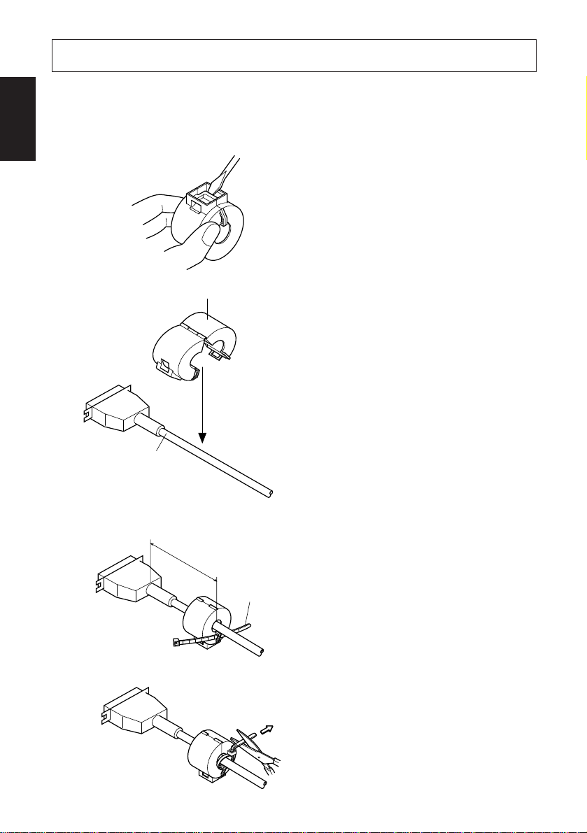
Interface Cable ...............................................................................................5
Connecting to a Peripheral Unit.....................................................................7
Connecting the Optional AC Adapter............................................................8
Turning Power On .........................................................................................9
Control Panel and Other Functions.................................................................10
Control Panel ...............................................................................................10
Errors ...........................................................................................................10
Self Printing .................................................................................................12
Loading the Roll Paper .....................................................................................13
Adjusting the Near-end Sensor ........................................................................16
Preventing and Clearing Paper Jams ..............................................................18
Preventing Paper Jams .................................................................................18
Removing Paper Jam ...................................................................................18
Periodical Cleaning ...........................................................................................19
Cleaning the Thermal Head .........................................................................19
Cleaning the Paper Holder ...........................................................................19
Appendix A: Specifications..............................................................................123
A-1. General Specifications ........................................................................123
A-2. Auto Cutter Specifications ..................................................................124
A-3. Interface ..............................................................................................124
A-4. Electrical Characteristics ....................................................................124
A-5. Option .................................................................................................124
A-6. Environmental Requirements..............................................................125
A-7. Reliability............................................................................................125
A-8. Black mark specifications ...................................................................126
Appendix B: Dip Switch Setting......................................................................127
B-1. Parallel Interface Type ........................................................................128
B-2. Serial Interface Type...........................................................................130
B-3. USB Interface Type ............................................................................133
B-4. Ethernet Interface Type.......................................................................134
Appendix C: Parallel Interface .......................................................................135
Appendix D: Serial Interface...........................................................................136
D-1. RS-232C Connector ............................................................................136
D-2. Cable Connections ..............................................................................138
D-3. Electrical Characteristics ....................................................................138
Appendix E: Periheral Unit Drive Circuit .....................................................139
Appendix F: Memory Switch Settings ............................................................140
ENGLISH

– 1 –
ENGLISH
Parts Identification and Nomenclature
Roll paper User’s manual
Cover open lever
Pull this lever in the
direction of the
arrow to open the
printer cover.
Control panel
Features LED indica-
tors to indicate printer
status and switches to
operate the printer.
Ferrite core Fastener
(Parallel interface
model only) (Parallel interface
model only)
Printer cover
Open this cover to load or
replace paper.
Power connector
For connection of
the AC adapter.
Never unplug the
AC adapter while
the printer is on.
Peripheral drive connector
Connects to peripheral
units such as cash
drawers, etc.
Do not connect this to a
telephone.
Interface connector
For connection to a
host computer.
Power switch
Used to turn on/off
power to the printer.

–2 –
ENGLISH
Choosing a place for the printer
Before actually unpacking the printer, you should take a few minutes to
think about where you plan to use it. Remember the following points
when doing this.
✓Choose a firm, level surface where the printer will not be exposed to
vibration.
✓The power outlet you plan to connect to for power should be nearby
and unobstructed.
✓Make sure that the printer is close enough to your host computer for
you to connect the two.
✓Make sure that the printer is not exposed to direct sunlight.
✓Makesurethattheprinteriswellawayfromheatersandothersources
of extreme heat.
✓Make sure that the surrounding area is clean, dry, and free of dust.
✓Make sure that the printer is connected to a reliable power outlet. It
should not be on the same electric circuit as copiers, refrigerators, or
other appliances that cause power spikes.
✓Make sure that the room where you are using the printer is not too
humid.

–3 –
ENGLISH
Consumable Parts and AC Adapter
When consumable parts have run out, use those specified in the table below.
Make sure that the AC adapter specified in the table is used.
Use of consumable parts or AC adapter which are not specified in the table may
result in damage to the printer, fire or electric shock.
(1) Roll paper specification
Thermal paper
Thickness: 65~150
∝
m
Width: 79.5±0.5 mm or 82.5±0.5 mm or 57.5±0.5 mm
Outer roll diameter: ø100 mm or less
Take up paper roll width: 80 mm or 83 mm or 58 mm
Core outer/inner diameter
Paper thickness Core outer Core inner
65~75
∝
mø18±1 mm ø12±1 mm
65~75
∝
mø32±1 mm ø25.4 mm
75~150
∝
mø32±1 mm ø25.4 mm
Printed surface: Outer edge of roll
Tail end handling: Do not use paste or glue to secure the roll paper or
its core.
Do not fold the tail end of the paper.
(2) Recommended paper
Mitsubishi Paper Mills Limited
P220AG (normal type paper), 65
∝
m (thickness)
HP220A (high image stability paper), 65
∝
m (thickness)
HP220AB-1 (high image stability paper), 75
∝
m (thickness)
P220AB (normal type paper, card ticket), 85
∝
m (thickness)
P220AC-1 (normal type paper, card ticket), 95
∝
m (thickness)
P220AC (normal type paper, card ticket), 105
∝
m (thickness)
P220AD (normal type paper, card ticket), 130
∝
m (thickness)
P220AE-1 (normal type paper, card ticket), 150
∝
m (thickness)
PB670 (2 color paper: Red & Black), 75
∝
m (thickness)
PB770 (2 color paper: Blue & Black), 75
∝
m (thickness)
Oji Paper Co., Ltd.
PD150R (normal type paper), 75
∝
m (thickness)
PD160R (high image stability paper), 65/75
∝
m (thickness)
PD750R (2 color paper: Red & Black), 75
∝
m (thickness)
PD700R (2 color paper: Blue & Black), 75
∝
m (thickness)
Nippon Paper Industries
TF50KS-E2C (normal type paper), 65
∝
m (thickness)
+0.5
-1 +0.5
-1 +0.5
-1

–4 –
ENGLISH
Kanzaki Specialty Papers Inc. (KSP)
P320RB (2 color paper: Red & Black), 65
∝
m (thickness)
P320BB (2 color paper: Blue & Black), 65
∝
m (thickness)
Depending on the type and thickness of the paper, it may be necessary to change
the settings for printing darkness. To change the darkness settings, use the
printing darkness settings command <ESC><RS> ‘d’n. Refer to the separate
programmer’s manual for details.
(3) AC adapter (option)
Model name: PS60A
Input: 100 to 240 V AC, 50/60 Hz
Output: DC24±5%, 2.0 A (5.0 A Load 10 sec. Max)

–5 –
ENGLISH
Connecting Cables and AC Adapter
Interface Cable
Ferrite Core Installation (Parallel interface model only)
(1)Foronlytheparallelinterfacemodel,
affix the ferrite core onto the cable
as shown in the illustration below.
(2)Pass the fastener through the ferrite
core.
(3)Loop the fastener around the cable
and lock it. Use scissors to cut off
any excess.
Ferrite core
Interface cable
5 cm
maximum
Fastener
Pull and cut

–6 –
ENGLISH
Connecting the Interface Cable
Note: Before connecting/disconnecting the interface cable, make sure that
power to the printer and all the devices connected to the printer is
turned off. Also make sure the power cable plug is disconnected from
the AC outlet.
(1)Connect the interface cable to the connector on the rear panel of the printer.
(2)In the case of a serial interface, tighten the connector screws. In the case of a
parallel interface, fasten the connector clasps.
Serial interface cable
Parallel interface cable

–7 –
ENGLISH
Connecting to a Peripheral Unit
You can connect a peripheral unit to the printer using a modular plug. The
followingdescribeshowtoinstalltheferritecoreandmaketheactualconnection.
See “Modular plug”on page 96 for details about the type of modular plug that is
required. Note that this printer does not come with a modular plug or wire, so it
is up to you to obtain one that suits your needs.
Important!
MakesurethattheprinteristurnedoffandunpluggedfromtheACoutlet
and that the computer is turned off before making connections.
(1)Connect the peripheral drive cable to the connector on the rear panel of the
printer.
Important!
Do not connect a telephone line into the peripheral drive connector.
Failure to observe this may result in damage to the printer.
Also, for safety purposes, do not connect wiring to the external drive
connector if there is a chance it may carry peripheral voltage.
(2) Connect the ground wire. (Europe only)
Take out the screw shown in the figure below, then fasten the ground wire
terminal to the place where the screw was removed and tighten the screw.
Europe only

–8 –
ENGLISH
Connecting the OptionalAC Adapter
Note: Before connecting/disconnecting the AC adapter, make sure that
power to the printer and all the devices connected to the printer is
turned off. Also make sure the power cable plug is disconnected from
the AC outlet.
(1)Connect the AC adapter to the power cable.
Note: Use only the standard AC adapter and power cable.
(2)Connect AC adapter to the connector on the printer.
(3)Insert the power cable plug into an AC outlet.
Important!
When disconnecting the cable, take hold of the
cable connector to pull it out. Releasing the lock
makes it easy to disconnect the connector.
Pullingthecableexcessivelycouldcausedamageto
the connector.

–9 –
ENGLISH
Power switch
3-4. Turning Power On
Make sure that the AC adapter has been connected as described in 3-3.
(1)Set the power switch located on the front of the printer to on.
The POWER lamp on the control panel will light up.
Important!
We recommend that you unplug the printer from the power outlet
whenever you do not plan to use it for long periods. Because of this, you
should locate the printer so that the power outlet it is plugged into is
nearby and easy to access.

–10 –
ENGLISH
Control Panel and Other Functions
Control Panel
1POWER lamp (Green LED)
Lights when the power is ON
2ERROR lamp (Red LED)
Indicates various errors in combi-
nation with POWER lamp
3FEED button
Press the FEED button to feed roll
paper.
Errors
1) Automatically recoverable error
2) Recoverable error
Note
1) If the cutter doesn’t return to the home position, or doesn’t perform the
initial movement, it cannot be recovered.
2) If the paper is jammed, turn the power off, clear the jammed paper, then
turn the power ON.
POWER lamp
Flashes at 0.5 sec-
ond intervals
On
Recovery Conditions
Automatically recovered after the
print head has cooled.
Automatically recovered by closing
the printer cover.
Error Description
Head high tem-
perature detection
Cover open error
ERROR lamp
Off
On
POWER lamp
Off
Recovery Conditions
Recovered If the cutter returns to the
homepositionafterturningthepower
OFF and ON.
Error Description
Paper cut error
ERROR lamp
Flashes at 0.125
second intervals
1POWER lamp (Green LED)
3FEED button
2ERROR lamp
(Red LED)

–11 –
ENGLISH
3) Non recoverable error
Note
1) If a non recoverable error occurs, turn the power OFF immediately.
2) When Power supply error occurs, there is a possibility that the power
supply unit has a trouble.
For other non recoverable errors, please consult the dealer for repairs.
4) Paper detection error
POWER lamp
Off
Flashes at 0.25
second intervals
Flashes at 0.5 sec-
ond intervals
Flashes at 1 sec-
ond intervals
Recovery Conditions
This is not a recoverable error.
Consult dealer for repairs.
This is not a recoverable error.
Consult dealer for repairs.
This is not a recoverable error.
Consult dealer for repairs.
Error Description
RAM error
MemorySWerror
Thermistor error
Power supply er-
ror
ERROR lamp
On
Flashes at 0.25
second intervals
Flashes at 0.5 sec-
ond intervals
Flashes at 1 sec-
ond intervals
POWER lamp
On
On
Recovery Conditions
Automatically recovered by loading
a new paper roll, then closing the
printer cover.
Indicators show that the paper end is
approaching, but the printer contin-
ues to print.
Error Description
Paper out error
Paper near end
ERROR lamp
Flashes at 0.5 sec-
ond intervals
Flashes at 2 sec-
ond intervals

–12 –
ENGLISH
Self Printing
(1)Test Printing
Turn the power on while holding the FEED button depressed.
TestprintingwillbeperformedaccordingtotheVer.No.,DIPswitchsettings
andcharacterorder. WhentheFEEDbuttonisdepressedatthetimeoftheend
of test printing, only the characters will be printed out repeatedly.
(2) Hexadecimal Dump Mode
Opentheprintercover,thenturnthepoweronwhileholdingtheFEEDbutton.
Whenthe cover is closed, “*** HEX DUMPPRINTING ***”is printed, and
the printer enters the Hexadecimal Dump Mode.
Each of the signals sent from the computer to the printer will be printed out
in hexadecimal code.
This function allows you to check if a control code sent to the printer by the
program being used is correct or not. The final line is not printed if its data is
less than one full line. However, if the FEED button is pushed, the final line
is printed. To turn off the mode, it is necessary to turn off the printer
completely.

–13 –
ENGLISH
Loading the Roll Paper
Be sure to use roll paper that matches the printer’s specification.
When using a paper roll with an 82.5 mm width, remove the paper roll holder as
described on the following page. Push the Cover open lever, and open
the printer cover.
While observing the direction of the
roll, set the paper roll into the hollow,
and pull on the leading edge of the
paper toward you.
Note 1: Whenusingpaperwithathick-
ness which requires the use of the ten-
sion bar (65
∝
m
paper thickness<100
∝
m),besurenottopassthepaperunder
the tension bar.
Cover open lever
Roll paper
Tension bar

–14 –
ENGLISH
Note2:Whenusingpaperwithathick-
ness which does not require the use of
the tension bar (100
∝
m
paper thick-
ness
150
∝
m), remove the tension bar
unit by removing the clips at both ends
of the bar with a flat head screwdriver.
Then, lower the right and left adjust-
ment levers by unhooking them with a
flat head screwdriver first, then lower-
ing them to the proper position.
Ordinarily, your dealer should have
already done these procedures.
Whenusingapaperrollwithan82.5mm
width, be sure to remove the paper roll
holder. Then, change the setting for
memory switch 4 to change the print
width from 72 mm to 80 mm.
For instructions on setting the memory
switch,pleaserefertotheseparatePro-
grammer’s Manual.
Whenusingapaperrollwitha57.5mm
width, install the paper roll holder in
the groove in the printer. Then, change
the setting for memory switch 4 to
change the print width from 72 mm to
52.5 mm or 50.8 mm.
For instructions on setting the memory
switch,pleaserefertotheseparatePro-
grammer’s Manual.
Note: If a paper roll with a 57.5 mm
widthhasbeenused,a paper roll witha
79.5 mm or 82.5 mm width cannot be
used. (Changing from the smaller roll
to a larger roll will cause part of the
print head to rub against the platen and
deteriorate.)
Paper roll holder

–15 –
ENGLISH
Important!
1. Do not touch the cutter blade.
· Thereisacutterinsidethepaperoutletslot.Notonlyshouldyounot
put your hand in the paper outlet slot while printing is in progress,
never put your hand into the outlet even when printing is not in
progress.
· The printer cover can be opened when replacing the paper. How-
ever, since the cutter blade is on the inside of the printer cover, be
carefulnot to place yourface or hands tooclose to the cutterblade.
2. Do not operate the cover open lever while pressing on the printer
cover with your hand.
3. Do not pull out paper while the printer cover is closed.
4. The heating element and the driver IC of the thermal head are easily
damaged. Do not touch them with metal objects, sandpaper, etc.
5. During and immediately after printing, the area around the thermal
head is very hot. Do not touch it, as you could be burned.
6. Printing quality may suffer if the thermal head heating element
becomes soiled by being touched with your hands. Do not touch the
thermal head heating element.
7. There is a risk of damage to the driver IC of the thermal head from
static electricity. Never directly touch the IC.
8. The printing quality and working life of the thermal head cannot be
guaranteed if any paper other than that recommended is used. In
particular, paper containing [Na+, K+, C1-] may drastically reduce
the working life of the thermal head. Please exercise caution.
9. Do not operate the printer if there is moisture on the front surface of
the head from condensation, etc.
Push down both sides of the printer
cover to close.
Note: Make sure that the printer cover
is securely closed.

–16 –
ENGLISH
Adjusting the Near-end Sensor
Usethefollowingproceduretoadjustthenear-endsensorsoitiscompatiblewith
the size of roll paper you are using.
1Open the printer cover.
2Determine the diameter of the roll paper you are using and find the required
setting in the table below.
3Insert the tip of a ballpoint pen or similar object into the hole of the adjuster,
and then push and side the adjuster to the desired setting.
When changing the setting, make sure that the position of the hole is aligned
with the alignment mark indicated by the arrow.
(Level 1) (Level 2) (Level 3)

–17 –
ENGLISH
Adjustment value according to the paper you are using
Note
1) The standard model is set to level 1
prior to being shipped from the fac-
tory.
2) The C dimension and the remained
paper length are the calculated val-
ues. There may be some variations
in actual mechanism.
3) Ifthickpaperisused(100∝m
paper
thickness
150 ∝m there will be
looseness in the roll paper itself
which makes it easier for detection
variations to occur. Set to Level 3.
Whenusing thepaperrollwithacorewhoseinsidediameter(A):ø12,outsidediameter
(B):ø18
Level 1 Level 2 Level 3 Level 1 Level 2 Level 3
ø23 ø27 ø31 2.5 4.9 7.7
2.1 4.2 6.7
Paper thick-
ness(
∝
m)
65
75
Remained paper length
(Approx. m)
Detected diameter (C)
(Approx. mm)
When using the paper roll with a core whose inside diameter (A): ø25.4, outside
diameter (B):ø32
Level 1 Level 2 Level 3 Level 1 Level 2 Level 3
ø36 ø40 ø44 2.8 6.4 10.4
2.4 5.5 9.0
2.1 4.9 7.9
1.9 4.4 7.1
1.7 4.0 6.4
1.4 3.2 5.2
1.2 2.8 4.5
Paper thick-
ness(
∝
m)
65
75
85
95
105
130
150
Remained paper length
(Approx. m)
Detected diameter (C)
(Approx. mm)
C
C
B
A
Roll paper core
Table of contents
Languages:
Other Oki Printer manuals

Oki
Oki C9650n User manual

Oki
Oki OKIPAGE 4W PLUS Reference guide

Oki
Oki ML421 Series User manual

Oki
Oki 80 Series User manual

Oki
Oki ES2232a4 User manual

Oki
Oki ML5520 User manual

Oki
Oki ES5442 Setup guide

Oki
Oki LP470b User manual

Oki
Oki CX3535MFP Operating and maintenance instructions

Oki
Oki MICROLINE 385/6 User manual

Oki
Oki OKIPAGE 8z How to use

Oki
Oki Executive Series 3037 User manual

Oki
Oki C 5650dn Installation guide

Oki
Oki ML8810 User manual

Oki
Oki C9650hdn User manual

Oki
Oki C7300 User manual

Oki
Oki C9600hnColorSignage User manual

Oki
Oki C8800 series User manual

Oki
Oki B710n Quick start guide

Oki
Oki C 5650dn Installation instructions