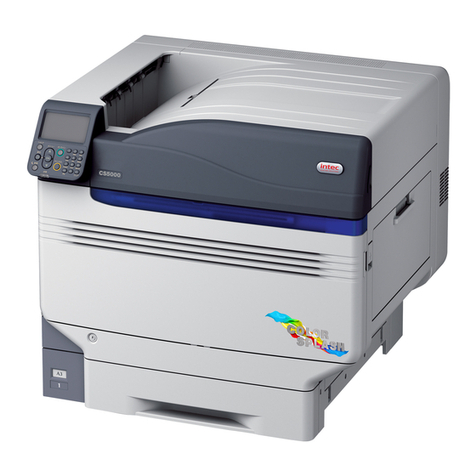
Intec CS4000 Assembly instructions

Version 2 |NOV 2015
Intec ColorSplash CS4000 and CS5000
Enhanced Print Production Envelope Feeder
Installation and Set Up Guide

CONTENTS
1. GETTING STARTED
1.1. ColorSplash EPP Envelope Feeder Components 3
1.2. Control Panel Components and Features 4
2. INSTALLATION GUIDE 5
2.1. Preparing the INTEC CS4000 / CS5000 Printer for use with your
Intec EPP Envelope Feeder 5
2.1.1. Removing the MPT Tray/Door 5
2.1.2. Removing the Outer Separation Pad 6
2.1.3. Installing Non-Reflective Aid for Envelope Feeders Optical Sensors 6
2.2. Assembly of the Intec ColorSplash Envelope Feeder 7
2.2.1. Assembly of Top Plate 8
2.2.2. Assembly of the Feeder Bridge 8
2.2.3. Fitting the Paper Hold Down Strap 9
2.2.4. Positioning the Envelope Buckle Separator 10
3. OPERATING GUIDE 11
3. Setting up the Feeder for envelopes 11
3.1. Setting the Hopper Paper Guides 11
3.2. Setting the Envelope (Buckle) Separator(s) 13
3.3. Setting up the Back Wedge 16
3.3.1. Purpose of the Back Wedge 16
3.3.2. Setting the Back Wedge for small / medium envelopes 16
3.3.3. Setting the Back Wedge for large envelopes 18
3.4. Setting the Acceleration Table Paper Guides 19
4. CHECKING YOUR FEEDER SETUP 21
5. DAILY OPERATION (Running envelopes with your printer) 22
5.1. Mounting/Connecting your Envelope Feeder 22
5.2. Envelope Feeder’s latch mechanism 23
5.3. Setting the Feeder’s speed control 24
5.4. Resume feeding switch /paper out sensor control 24
5.5. Paper jam or feeder out condition 25
5.6. Setting the Intec ColorSplash Envelope Feeder’s speed control 26
5.7. Removing the Feeder from the printer 26
6. TROUBLESHOOTING 27
6.1. Note on new ColorSplash printers 27
6.2. Common issues 27
2

1. GETTING STARTED
1.1. ColorSplash EPP Envelope Feeder Components
Back Wedge assembly
Paper guide assembly Bridge
Paper guide hopper
adjustment knob
Buckle separator assembly
Acceleration table
paper guide
Optical sensor
(RESTART envelopes)
Optical sensor (STOP envelopes)
Acceleration table
Envelope hold
down strap
Acceleration table
paper guide
Feed belts
IMPORTANT: Please familiarize yourself with the components shown above. These
components are referred to in the setup instructions contained in this manual.
3

1.2. Control Panel Components and Features
Timeout reset / Jog button*
24 VDC power input jack Fuse holder (5 amp fuse)Ready/Feed switch Speed adjust knob
Mains power switch
The ColorSplash’s EPP Envelope Feeder
features a timeout function. During
operation, if the optical sensor mounted at
the exit end of the acceleration table (the
STOP Envelope Sensor) does not detect
an envelope for 4 seconds, the feed motor
will be paused. This is to ensure that the
motor does not ‘run on’ in the event the
feeder runs out of envelopes, or a jam
occurs in the feeder.
The Reset / Jog button shown above is
used to reset the timer and allow the motor
to restart running after a timeout occurs.
If you press and hold this button in,
the motor will run continuously until an
envelope covers the optical stop sensor.
The variable speed control can be
adjusted to accommodate different size
envelopes. As a general rule, most small
envelopes will require approximately 50%
maximum speed or more. For envelopes
150mm (6" long) in the running direction or
longer, higher speeds will be required for
consistent operation.
The feeder utilizes a low voltage 24 VDC\5
amp external power supply. An on board
5 amp fuse is included for electrical
component protection. This fuse can be
accessed by unscrewing the fuse cap in
the lower right corner of the control panel.
*TIMEOUT FEATURE
4

2. INSTALLATION GUIDE
The Intec ColorSplash’s EPP Envelope Feeder is designed to operate with the new Intec ColorSplash digital production
printers. This guide will show the proper way to prepare the printer for the envelope feeder and installation and operation
of the feeder.
2.1. Preparing the INTEC CS4000 / CS5000 Printer for use your Intec EPP
Envelope Feeder
2.1.1. Removing the MPT Tray/Door
Step 4. Remove the left side of the door in the same
fashion and remove the door from the printer.
Step 3. Press inward on the pivot point of the
door on the right side to remove it
from the printer housing.
Step 2. Press inward on the right side hinge
of the door to release it from the slot.
Step 1. To prepare the ColorSplash CS4000/
CS5000 printer for the feeder, you must
first remove the door from the manual
feed tray. First, open the manual feed
tray door on the right side of the printer.
5
1
3
2
4

2.1.2. Removing the Outer Separation Pad
Step 6. With the right side door fully open,
lift the feed roller assembly to gain
access to the feed roller and sheet
separator area.
Step 7. Pinch the two upper corners of the
sheet separator assembly (rubber
pad) and remove the assembly from
the printer.
Remove the separator assembly
NOTE: The envelope feeder is equipped with paper sensors positioned just to the left of
the printer’s manual feed tray feed roller and in the centre of the floating delivery table. It is
possible for the sensors to detect the white plastic housing just to the left of the feed roller,
and reflective silver housing above the middle sensor, which can cause erratic feeding.
It is very important to place the black tape or Velcro™ (included with feeder) in these 2 positions.
Note: This tape will not affect the printer and can be left in place, even when not using envelope feeder
Place black
tape
in these areas
6
Step 5. Open the right side cover on the printer by
pulling on the latch shown here:
5
6
7

2.2. Assembly of the Intec ColorSplash Envelope Feeder
Step 1. After removing the feeder from the shipping container, carefully place the feeder
and cabinet in the upright position.
Step 2. Open the door on the rear of the cabinet and remove the accessories box.
Step 3. Carefully remove the contents of the accessories box and set them on a table.
Ensure that all of the components listed below are accounted for before discarding the packaging.
Additional items included in the accessories box include:
• Extra sheet separator
• Envelope buckle device
• Black Velcro™ patches for printer
• 24 VDC power supply
• Narrow back wedge assembly
Hold down strap and shoulder screw
Top plate and back wedge assembly
Bridge
1/8" Allen wrench
7

5
7
8
9
2.2.1. Assembly of Top Plate
Step 4. Using the included 1/8" Allen wrench, remove
the four button head screws from the top of
the back plate of the feeder.
Step 5. Attach the top plate to the feeder
using the four button head screws
removed in Step 4.
Step 6. Tighten the screws holding the top
plate securely.
Step 7. Using the 1/8" Allen wrench, remove the two flat
head screws from each end of the bridge.
Step 8. Carefully position the bridge between the
side plates of the feeder and line up the
attaching holes.
2.2.2. Assembly of the Feeder Bridge
Step 9. Attach the bridge to the feeder using
the four flat head screws removed
from the bridge in Step 7.
Step 10. Tighten all four bridge screws.
Do not tighten any of the screws until
all four are in place.
Be careful on steps 4 & 5 not to drop
the screws into the feeder.
8
4

2.2.3. Fitting the Paper Hold Down Strap
Step 11. Remove the shoulder screw from the paper hold down strap pivot block.
Step 12. Place the end of the hold down strap (opposite pivot
block end) underneath the acceleration table cross bar
and on top of the transport belt.
Step 13. Position the hold down strap pivot block next to the
mounting block (on the right side) on the bridge and
insert the shoulder screw into the pivot block.
Step 14. Attach the pivot block to the mounting block on the
bridge using the 1/8" Allen wrench to tighten securely.
The hold down strap assembly should
pivot at the shoulder screw and should lie
flat on the transport belt.
The steel weights on the strap apply downward
pressure on the envelopes to ensure consistent
movement of the envelopes by the transport belt.
Strap weights
Pivot block for paper
hold down strap
Shoulder screw
9
12
13
14

15
16
17
2.2.4. Positioning the Envelope Buckle Separator
Step 15. Loosen the locking knob holding the envelope buckle
separator in position on the bridge.
Step 16. Slide the buckle separator to the
center of the feeder and position the
yellow tip at the bottom between
the two center feed belts as shown
in the photo.
Step 17. Lock the separator
in position with the
locking knob.
10

2
3. OPERATING GUIDE
IMPORTANT: It is recommended that you set up the feeder for your envelopes before moving
the feeder into position with the printer. This will ensure complete access to the paper guides
on the acceleration table and make testing the feeder easy.
The ColorSplash’s EPP Envelope Feeder can feed a variety of envelope sizes and types into the printer via the printer’s
manual feed tray. The following instructions illustrate the proper setup of the feeder.
Note: The feeder can be setup for your envelopes away from the printer and then easily placed in line with the printer
after setup is complete.
Setting up the Feeder for Envelopes
Setting the feeder for your envelopes consists of the following basic steps:
1. Setting up the hopper paper guides
2. Setting up the sheet separator(s)
3. Setting the back wedge (envelope stack support)
4. Setting the delivery table paper guides
5. Testing the feeder
6. Moving the feeder into position alongside the printer
3.1. Setting the Hopper Paper Guides
Step 1. Ensure that the main power switch on the feeder’s
control panel is in the OFF position and plug the 24
VDC power supply, included with the feeder, in the
power jack on the control panel.
Step 2. Rotate the paper guide adjusting knob on the bridge
to position the paper guides outward toward the side
plates of your feeder.
24 VDC power input
11
1

3
6 7
Step 3. Loosen the locking knobs on the acceleration table
paper guide blocks and slide the acceleration table
paper guides outward. Grasp the paper guide
block to move the guides.
Locking knobs
Step 4. Loosen the back wedge assembly locking knob
and slide the back wedge back away from the feed
belts for easy access to the envelope hopper area.
Step 5. Place one of your envelopes between the hopper
paper guides above the feed belts.
Step 6. While holding the envelope with one hand, rotate the paper guide adjusting knob to move the
paper guides in until they are alongside the edges of your envelope.
Do not pinch the envelope with the Hopper paper guides.
12
4
5

The ColorSplash EPP Envelope Feeder utilizes a patented technique for separating the bottom envelope from the stack
called 'buckle separation'. This unique method separates the envelopes by buckling them downward between feed
belts. This results in simple sheet separation and minimizes envelope scuffing and paper jams.
You will notice in the following instructions that the separator(s) are positioned between the
feed belts, not over them.
When in this position, the separators push down on the envelope as it is advanced from the bottom of the stack, forming
a downward 'buckle' in the envelope between feed belts.
This method is simple, effective, easy to set up and does not require a lot of fine tuning. The downward buckle breaks
the friction 'bond' between the bottom envelope and the stack, making it easier to pull the bottom envelope away.
This method of separation also reduces jams because with the separators pushing down on the envelope between,
rather than on top of, the feed belts, there is not a 'pinch point' created.
The EPP Envelope Feeder comes with two buckle separator assemblies. Most jobs only require the use of one
separator so we recommend trying a single one in the middle first as shown here:
3.2. Setting the Envelope (Buckle) Separators(s)
If you are not getting consistent results after some time and adjustments, you may wish to try two separators as
shown here:
Note that in both examples above, the separators are positioned between belts.
Single separator
(positioned between belts)
Separator locking knob
(loosen to reposition
separator(s))
Two separators.
Each positioned between
two feed belts
13

1
2
3
4
3.2 Setting the Envelope Separator(s) (continued)
Step 1. If using a single separator (recommended), ensure
that the buckle separator is positioned in the gap
between the two center feed belts.
Step 2. Rotate the separator height adjustment knob
clockwise several turns to raise the separator
tip up above the level of the feed belts.
Step 3. Place the lead edge of your envelope under the
buckle separator’s yellow tip as shown below.
Separator height adjustment knob
Separator tip (yellow)
Step 4. Slowly turn the separator height adjustment
knob counter-clockwise to lower the separator tip onto
the envelope.
14

5
Step 5. Continue to slowly lower the separator tip until the envelope is buckled downward between the
belts slightly (approx 2mm (1/16") to 3mm (1/8").
NOTE: Ensure that the separator tip is between feed belts so it does not 'pinch' the envelope.
Step 6. (optional) If you are using two separators, repeat the above steps for both.
NOTES: The separators do not need a lot of fine tuning, as a small buckle is all that is required.
Some experimentation is recommended to get the best results with your materials.
One or both separators can be used as desired, but be sure to position the separators between belts and buckle the
envelopes down slightly.
There is no specific configuration that you must use as this design offers tremendous flexibility. If one setup doesn’t
work, try moving the separators to different positions across the feeder bridge.
Lower the separator tip to 'buckle' the envelope down between belts
15

3.3. Setting up the Back Wedge
Step 1. After setting the separator as shown in the
previous steps, leave one envelope in the
feeder, that you used for the separator setup.
Step 2. Carefully shingle out a small stack of envelopes so
that the bottom one will be the foremost envelope
in the stack as shown here.
Step 3. Place the stack in the hopper on top of the
envelope left on the belts from the separator
setup. Try to 'nudge' the envelopes a bit from the
back to help the stack conform to the curvature
of the paper guides at the bottom.
The back wedge, attached to the rear plate of the feed
hopper is a very important tool that must be set properly
to obtain the best results.
3.3.1. Purpose of the Back Wedge
The back wedge performs several important functions:
1. Supports the weight of the stack so that not all of the weight is on the belts.
2. Tilts the back end of the media stack up so the lead edge presses against the belts.
3. (most important) While the bottom envelope is getting pulled away from the stack by the feed belts, the
back wedge holds the other envelopes off the belts so they don’t advance too closely after the first one.
16
1
2
3

Step 4. With one hand, raise the back end of the
envelope stack up and then slide the back
wedge into position underneath the back
end of the stack. Lock the wedge in place
with the locking knob.
As shown in the pictures above and left, the back wedge
should be in just far enough to hold the back edge of the
envelope stack up off the belts.
Step 5. The angle of the back wedge can be adjusted to
assist with different kinds of envelopes. To adjust
the angle, loosen the locking lever on the side of
the back wedge.
Step 6. The height of the back wedge ramp can also be
adjusted by loosening the round locking knob on
the back of the upright as shown here. For smaller
envelopes, the top of the ramp should be slightly
below the top of the upright.
Back wedge upright
Locking lever
17
4
5
6

As with the separators, some experimentation would be helpful to obtain the best results.
3.3.3. Setting the Back Wedge for large envelopes
In addition to setting the paper guides properly for large envelopes, the back wedge will need to be adjusted.
For larger (longer) envelopes, you will need to move the back wedge further away from the bridge.
Larger (longer) envelopes have a tendency to 'sag' downward in the middle, which can cause double feeding or
inconsistent gaps between envelopes. This 'sagging' can be remedied by lowering the angle of the back wedge
and moving it a bit more underneath the stack of envelopes as shown below.
Back wedge locking knob
The back wedge ramp can be used to lift the middle of the envelopes off
the belts
18

After setting these guides, remove the envelope.
Note: The acceleration table paper guides can be locked in to position by tightening the paper guide block
locking knobs.
1
2
3.4. Setting the Acceleration Table Paper Guides
The patented 'floating' or tilting delivery table on the ColorSplash EPP
envelope feeder is designed to advance the envelopes that the feed belts
deliver, one at a time, into the printer’s manual feed tray feed roller.
The acceleration table is equipped with self centering paper
guides, an envelope drive belt and a stop photo sensor at the
end. The photo sensor is used to stop each envelope in position
underneath the printer’s feed roller, for take-away by the printer.
An additional photo sensor is positioned a few inches back
from the stop sensor. This is the restart sensor. When the first
envelope is pulled away by the printer, the trail edge of that
envelope uncovers the start sensor, which starts the feeder
motor. Using the dual sensors allows the ColorSpalsh EPP
envelope feeder to run larger envelopes at higher speeds.
Step 2. Grasp the acceleration table paper guide block and
slide the paper guides inward until they are close to
the edges of your envelope.
Lift hold down strap to place envelope
underneath
Step 1. After the feeder portion of the machine has been
set for your envelopes as per the previous section,
position one of your envelopes over the exit end of
the acceleration table between the paper guides.
Paper guide locking knob
Do not set the guides tightly against
the envelope. Too tight will restrict the
envelope movement.
19

The feeder should advance the bottom envelope from your stack until it reaches the exit end of the
acceleration table. When the envelope lead edge blocks the stop photo sensor, the feeder motor will stop.
3
4
5
Step 3. Set the speed control knob on the control
panel to approximately 20% to test the feeder.
Step 4. With the green feed switch in the off position, turn on
the feeder power with the red power switch.
Step 5. Move the green feed switch to the 'resume feeding'
position to start the feeder.
Note: Due to the downward angle of the
acceleration table, if you are running short
envelopes, the first envelope may fall off the
end of the acceleration table after pausing the motor
for a moment. If this happens, the stop photo sensor
will become unblocked and the feeder will advance
the next envelope. This is normal and does not
indicate a problem.
Note: The feeder has a 4 second timeout
feature that is used to stop the motor in the
event of a paper jam or if the feeder runs
out of envelopes. If, during this setup procedure, the
machine is set to run very slowly the envelope may
not reach the stop photo before the 4 second timer
stops the motor. If this happens, simply press the
reset button on the control panel to reset the timer
and start the motor. Stop photo sensor (under envelope)
20
Other manuals for CS4000
2
This manual suits for next models
1
Table of contents
Other Intec Printer manuals
