Intech 2400-IS User manual

Intech 2400-IS
Isolating Converter
USB/RS232 to RS485/422/232
Installation Guide.

2
2400-IS Isolating Converter Installation Guide:
Description Page 3
Ordering Information Page 3
Features Page 3
Specifications Page 3
Physical Layout Page 4
2400-IS Connections Page 4
Outstation Layout Page 6
2 Wire RS485 Connections Page 6
4 Wire RS422 Connections Page 7
Connection to a MicroScan SCADA System Page 8
Connecting a RS485 Field Station to an Existing RS422 Data Hi-way. Page 9
2300 Series Connections Page 10
Wiring and Installation Page 11
Product Liability. This information describes our products. It does not constitute guaranteed properties and is not intended to affirm the suitability of a
product for a particular application. Due to ongoing research and development, designs, specifications, and documentation are subject to change
without notification. Regrettably, omissions and exceptions cannot be completely ruled out. No liability will be accepted for errors, omissions or
amendments to this specification. Technical data are always specified by their average values and are based on Standard Calibration Units at 25C,
unless otherwise specified. Each product is subject to the ‘Conditions of Sale’.
Warning: These products are not designed for use in, and should not be used for patient connected applications. In any critical installation
an independent fail-safe back-up system must always be implemented.
3
2400-IS Isolating Converter
USB/RS232 to RS485/422/232.
Description:
The 2400-IS is a compact desktop module that isolates and converts
USB or RS232 from a computer to RS485, RS422 or RS232 for
communication to a field data logging system. It’s driver and receiver
meet EIA standards RS-422-A and CCITT recommendations V.11 and
X.27 and is designed for multipoint transmission on long bus lines in
noisy environments. The module can be powered from the computers
USB port, or from an external 5Vdc power adapter (not supplied).
Ordering Information:
2400-IS Isolated USB/RS232 to RS485/RS422/RS232 Converter.
Complete with:
- USB cable (length = 1m).
- RS232 cable (length = 2m) - for PC connection.
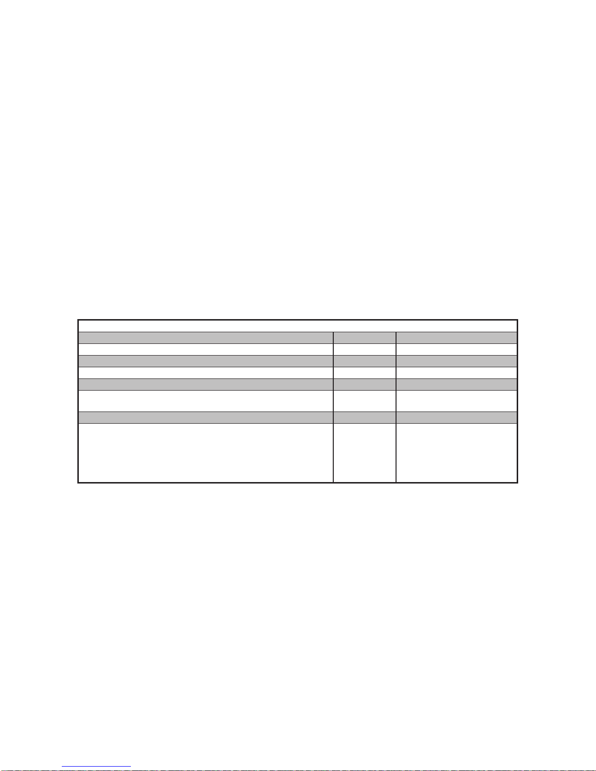
Specifications:
Power Supply 5Vdc.
Max Current 130mA.
Operating Temperature -40° ~ +85°C.
Computer Input Types:
USB USB-B type (Fully compatible with USB 2.0 connections).
RS232 DB9-Female.
Field Outputs:
RS485/422 5-pin screw terminal.
RS232 RJ-11.
Comms Baud Rates:
USB 300~256000 Baud.
RS485/422/232 300~128000 Baud.
Dimensions L=119mm, W=72mm, D=26mm.
Weight 0.1Kg.
Features:
Isolation Between Computer and Field.
Powered Via Computer USB Port, (or 5Vdc external power adapter not included).
Fully Compatible with USB 2.0.
Supports RS485 Field Stations / Controllers on an Existing RS422 Data Hi-way.
Supports Multiple Baud Rates.
Stylish Compact Desk Top Case.
Easy to Install.
Note: USB cable cannot exceed 5m.
RS232 cable cannot exceed 15m.

4
2400-IS Physical Layout:
LED indicators:
PWR Power status - Lights up when power is supplied to the USB
5VDC input.
USB USB status - Lights up when a USB or power adapter is
connected to the USB 5VDC input, and there is no RS232
cable connected to the RS232 DB9 Input. This indicates that
the module will convert the USB interface from the
computer to the RS485/422/232 interface of the field
devices.
RS232 RS232 status - Lights up when a RS232 cable is connected
to the RS232 DB9 input. This indicates that the module will
convert the RS232 interface from the computer to the
RS485/422 interface of the field devices.
Please note that the USB 5VDC input still requires a power
supply either from a USB port on your computer or an
external power adapter.
Rx Field receiving status - Lights up when the converter is
receiving data from the field devices.
Tx Field transmitting status - Lights up when the converter is
transmitting data to the field devices.
2400-IS Connections:
RS232 DB9 Input:
Pin 1: No Connection
Pin 2: Tx
Pin 3: Rx
Pin 4: No Connection
Pin 5: GND
Pin 6: No Connection
Pin 7: No Connection
Pin 8: No Connection
Pin 9: No Connection
74
COM 73
Rx+ 72
Rx- 71
Tx+ 70
Tx-
75
NC
RS485:
Pin 70: Tx-/Rx-
Pin 71: Tx+/Rx+
Pin 72: No Connection
Pin 73: No Connection
Pin 74: COM
Pin 75: No Connection
RS422:
Pin 70: Tx-
Pin 71: Tx+
Pin 72: Rx-
Pin 73: Rx+
Pin 74: COM
Pin 75: No Connection
5-Pin Screw Terminal Output:
5
RS232 RJ11 Output:
Pin 1: No Connection
Pin 2: Tx
Pin 3: Rx
Pin 4: No Connection
Pin 5: GND
Pin 6: No Connection
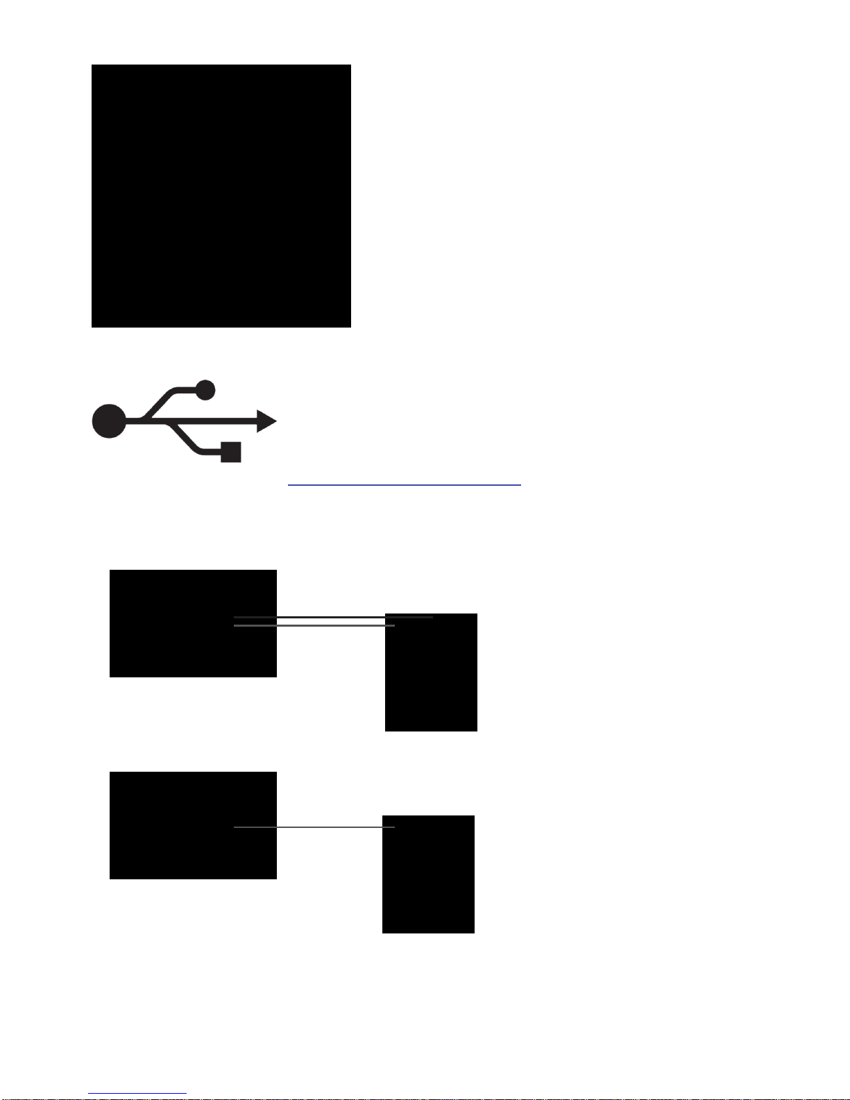
USB Output:
The USB output of the 2400-IS requires a driver before installation.
If you already have MicroScan V5 installed on your PC (Build: 5.0.3050.17 or later),
then the driver will already be installed. However if you need to install the driver
manually, then you can download the driver from the following location:
www.intech.co.nz/2400isdriver
Typical Input Examples:
Data via RS232, Power via USB:
MicroScan Computer.
2400-IS Converter.
RS232 Data Cable.
USB Power Cable.
MicroScan Computer.
2400-IS Converter.
USB Data & Power Cable.
Data and Power via USB:
2400-IS Converter automatically defaults to
RS232 COMMS when an RS232 cable is
detected. USB must also be connected for
power.

6
Shimaden SD16A/24/20 with RS485 option.
Shimaden SRS10A Series with RS485 option.
70
71
74
2100/2400-A16 Remote Station.
70
71
74
2100-D Remote Station.
70
71
74
2100-AO Remote Station.
70
71
74
2100-A4 Remote Station.
SRS 11A 12A 13A/14A
18 2 12 -
17 1 11 +
MR13
25 -
24 +
23 SG
SD 16A 24 20
- 17 3 21
+ 16 2 22
SG 15 1 1
Shimaden MR13 with RS485 option.
End of Data Highway Junction Box;
Resistor = 1KΩ.
1KΩ
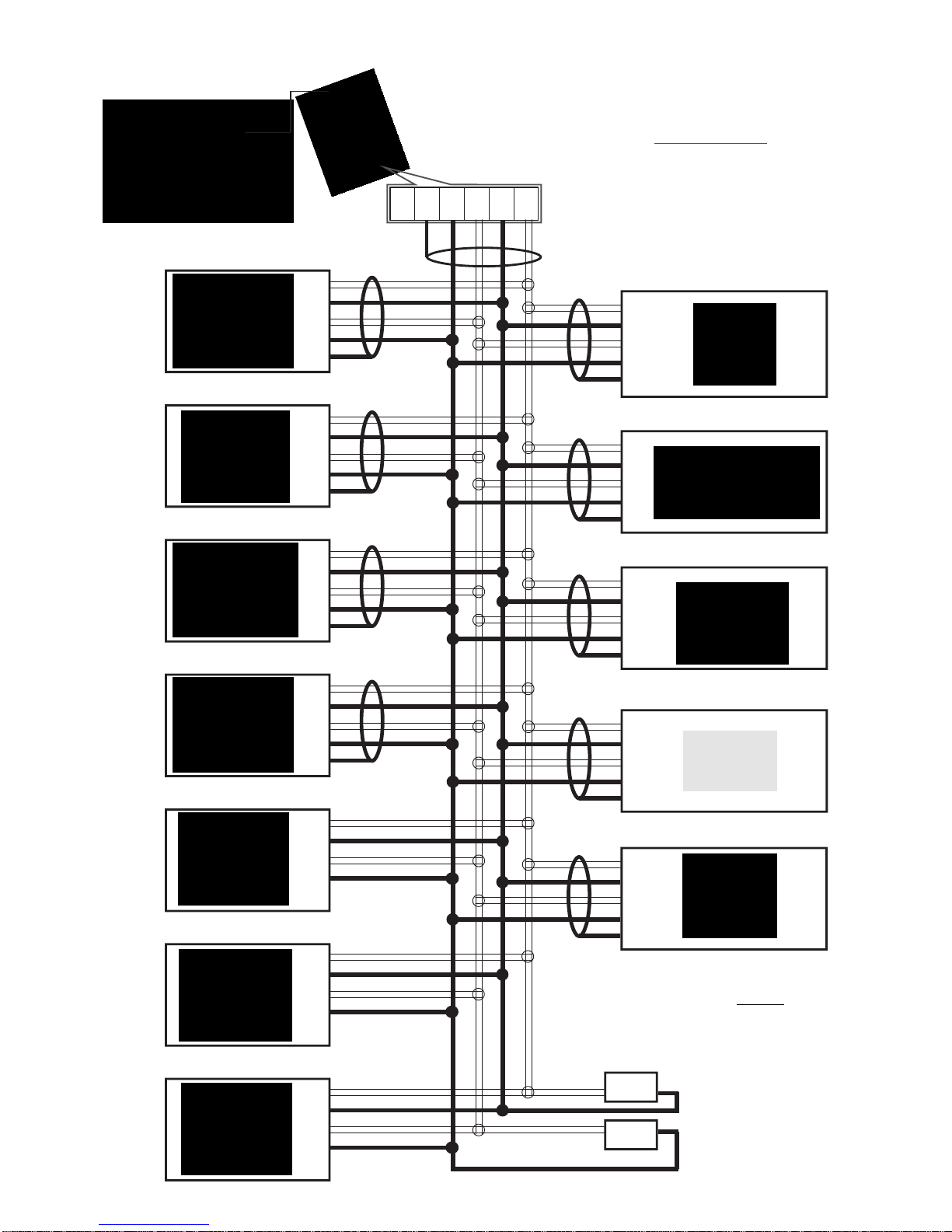
Outstation Layout - RS485:
2 Wire RS485 Connections:
Never guess Tx or Rx connections.
Follow the terminal numbers in the serial
connections diagrams exactly.
MicroScan Computer.
2400-IS Converter.
Important:
1. All cables must be screened.
2. All screens must be connected together.
3. The screen must not be earthed at any
point.
Shimaden SR90 Series with RS485 option.
SR 91 92/93/94
12 3 -
11 2 +
1 1 SG
TWISTED PAIR
RS485 DATA HI-WAY.
CABLE POLARITY
MUST BE OBSERVED.
SR 82 83 84
- 18 25 22
+ 17 24 21
SG 16 23 1
Shimaden SR80 Series with RS485 option.
74
com
71
Tx+ 70
Tx-
Shimaden FP93 with RS485 option.
FP93
- 25
+ 24
SG 23
Shimaden FP23 with RS485 option.
FP23
- 14
+ 13
SG 12
Shimaden SR23 with RS485 option.
SR23
- 14
+ 13
SG 12
Shimaden SR253 with RS485 option.
SR253
- 3
+ 9
SG 5
7
70
71
72
73
74
2100-D Remote Station.
70
71
72
73
74
2100-AO Remote Station.
70
71
72
73
74
2100-A4 Remote Station.
Shimaden SR53/54 with RS422 option.
25
24
23
22
21
24
23
21
22
1
Shimaden SD20 with RS422 option.
5
4
3
2
1
Shimaden SR73A/74A with RS422 option.
End of Data Highway
Junction Boxes;
Resistors = 1KΩ.
Outstation Layout - RS422:
4 Wire RS422 Connections:
Never guess Tx or Rx connections.
Follow the terminal numbers in the serial
connections diagrams exactly.
MicroScan Computer.
Important:
1. All cables must be screened.
2. All screens must be connected together.
3. The screen must not be earthed at any
point.
2400-IS Converter.
70
71
72
73
74
2100/2400-A16 Remote Station.
1KΩ
Shimaden SR25/253 with RS422 option.
4
6
3
9
5
21
20
23
22
IN-2000-AI Remote Station.
36
35
38
37
IN-2000-DI Remote Station.
26
25
28
27
IN-2000-DO Remote Station.
1KΩ
RS422 DATA HI-WAY.
CABLE POLARITY
MUST BE OBSERVED.
TWISTED PAIR
TWISTED PAIR
74
com 73
Rx+ 72
Rx- 71
Tx+ 70
Tx-
4
6
3
9
5
Shimaden FP21 with RS422 option.
Important: When an FP21 is
present all devices in the Data
Highway must use 4800 baud rate.

8
Connection to a MicroScan SCADA System:
RS485/422 Data Cabling Installation e.g. 1:
MicroScan Computer.
2400-IS Converter.
Spur Line
<30m
2400-A16.
Shimaden SR23.
2100-A16.
1KΩ
Terminating Resistors
at Cable End.
Spur Line
<30m
Spur Line
>30m
MicroScan Computer.
2400-IS Converter.
2100-A16.
2400-A16.
Shimaden SR23. 1KΩ
Terminating Resistors
at Cable End.
Terminating Resistors
at Cable End.
1KΩ
Spur Line
>30m
Spur Line
<30m
Spur Line
<30m
RS485/422 Data Cabling Installation e.g. 2:
2400-IS converter may be placed anywhere along
the data hi-way.
Note: Shimaden Controllers must have a unique serial number preprogramed before connecting to the COMMS data
hi-way. All signals and power must be de-energised before connecting to any wiring.
Note: Total length of trunk line, including spurs, is not to exceed, typically 500m using RS485 or typically 1200m using
RS422.
IMPORTANT: The Accompanying Installation Instructions must be strictly adhered to.
9
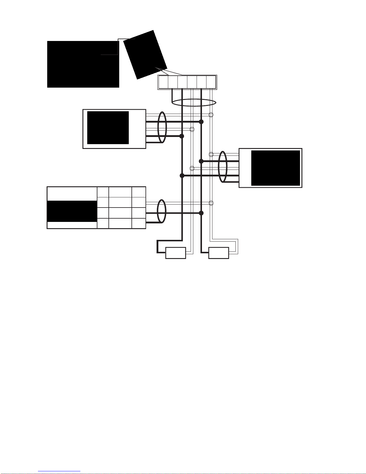
Connecting a RS485 Field Station / Controller to an Existing RS422 Data Hi-way:
MicroScan Computer.
2400-IS Converter.
2400-A16.
2100-A16.
1KΩ
End of Data Highway Junction Boxes;
Resistors = 1KΩ.
TWISTED PAIR
TWISTED PAIR
70
71
72
73
74
70
71
72
73
74
1KΩ
Shimaden SR90 Series with RS485 option.
SR 91 92/93/94
12 3 -
11 2 +
1 1 SG
74
com 73
Rx+ 72
Rx- 71
Tx+ 70
Tx-
Note: This type of connection is only supported by the 2400-IS converter.
RS422 Mode.
RS422 Mode.

10
2300 Series Connections:
MicroScan Computer.
2400-IS Converter.
70
71
70
71
70
71
2300 Series Remote Station.
2300 Series Remote Station.
2300 Series Remote Station.
2300 Series Remote Station.
Never guess Tx or Rx connections.
Follow the terminal numbers in the serial
connections diagrams exactly.
Important:
1. All cables must be screened.
2. All screens must be connected together.
3. The screen must not be earthed at any
point.
RS485 DATA HI-WAY.
CABLE POLARITY
MUST BE OBSERVED.
End of Data Highway Junction Box;
Resistor = 1KΩ.
TWISTED PAIR
70
71
1KΩ
Important: The 2300-XX stations cannot share a data hi-way with the 2100-XX / 2400-XX stations and/or Shimaden
Controllers.
74
com
71
Tx+ 70
Tx-
11
Wiring and Installation:
The Prober Installation and Wiring of the 2400-IS:
All power and signals must be de-energised before connecting any wiring, or altering any jumpers of dip switches.
Mounting:
1. Mount in a clean environment.
2. Do not subject to vibration, excess temperature or humidity variations.
3. Avoid mounting near power control equipment.
4. Allow 10mm minimum clearance between the 2400-IS terminals and ANY conductive materials.
Cover Removal:
Removing the cover of the 2400-IS will void the warranty.
Analogue Signal Cabling:
1. All analogue cables should be good quality, overall screened, INSTRUMENTATION CABLE, with the screen
earthed at one end only. (e.g. Austral Standard Cables B5102ES.)
2. Analogue signal cables should be laid at a minimum distance of 300mm from power and data cables.
3. It is recommended that you do not ground current loops or use power supplies with ungrounded outputs.
4. Lightning arresters should be used on inputs and outputs when there is a danger from this source.
5. Refer to diagrams for connection details.
RS485-422 Comms Signal Cabling:
1. Use only low capacitance, twisted pair, overall screened data cable. The cable must equal or better the following
specifications.
Conductor Size. 7/0.20mm, 24AWG
Conductor Resistance @ 20°C. 8.9Ω/100m
Max. Working Voltage. 300Vrms
Capacitance Between Wires of a Pair. 50ρF/m
Capacitance Between Each Wire to All Others Bunched Together. 95ρF/m
Cross-Talk Between Pairs. @ 1KHz
@ 100KHz >-90dB/100m
>-50dB/100m
Characteristic Impedance. @ 100KHz 135Ω
Cable Specifications.
Attenuation of a Pair.
@ 1KHz
@ 10KHz
@ 50KHz
@ 100KHz
@ 1MHz
@ 1.5MHz
.15dB/100m
.42dB/100m
.80dB/100m
.90dB/100m
1.9dB/100m
2.4dB/100m
Note: All cables are to be subject during manufacture to in-process spark testing @ 4kVrms.
All cables are to be tested between conductors and conductors to screen for 1min @ 1500Vrms.
2. Minimum cable pairs: RS485 = 1 (Plus overall screen), RS422 = 2 (Plus overall screen).
3. Take care not to stress or damage cables during installation.
4. Total length of trunk line, including spurs, is not to exceed, typically 500m using RS485 or typically 1200m using
RS422, without isolating boosters.
5. Terminating resistors - 1kΩ.
6. Cabling paths should avoid sources of radio frequency interferences such as fluorescent lights, variable speed
motor drives, wielding equipment, radio transmitters, etc.
7. There should be a minimum of 200mm physical separation between power cables and data cables.
8. Data cables should not be exposed to excessive heat or moisture, and should not be buried directly in the ground
without protection.
9. Avoid powering a remote station or controller form the same power supply as a variable speed drive.
10. All unused twisted pairs should be terminated at bother ends with 1kΩresistors. DO NOT ground unused pairs.
Commissioning:
1. Check that all the above conditions have been met, and that the wiring is checked, before applying power to the
2400-IS.
2. Check each relay output functions correctly, and the relay specifications are not being exceeded.

12 2400-IS 130412
www.intech.co.nz
Christchurch Ph: +64 3 343 0646
Auckland Ph: 09 827 1930
Table of contents
Other Intech Media Converter manuals


Popular Media Converter manuals by other brands

Hall Research Technologies
Hall Research Technologies TVB-400 manual

Audio Authority
Audio Authority BlueBeam C-1071A quick start guide

Snell Advanced Media
Snell Advanced Media MV-820 user manual

Vision HD
Vision HD HD0101 operating instructions

Elko
Elko inels RFSG-1M quick start guide

Parallax
Parallax PDT-DVC-8219-I Operation manual


