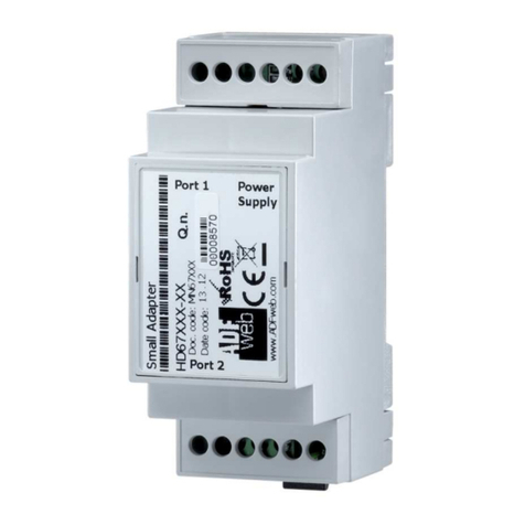
Intech Micro 2300-NET User manual

14.29-1
INTECH Micro
2300-NET
Installation Guide.
Overview.
The 2300-NET is an Ethernet to serial (RS485) bridge specifically designed to connect the 2300 series I/O stations to
the 10/100 Base-TX Ethernet network. This facilitates the MicroScan V5 SCADA software to allow remote I/O station
addressing to the 2300 series stations via the Ethernet TCP/IP network.
The 2300-NET can also be configured to operate in a number of different modes including as a gateway function of
converting Modbus TCP messages to Modbus RTU messages.
10/100 Ethernet to RS485 Converter.

14.29-2
2300-NET Installation Guide Index.
Features. Page 3
Specifications. Page 4
Dimensions. Page 4
Power Connections. Page 5
Ethernet Connection. Page 5
Indication LED’s. Page 5
Computer to 2300 Series Comms Connections - 2300-NET. Page 7
2300-NET RS485 Settings. Page 10
Troubleshooting Guide. Page 10
Wiring and Installation. Page 11
Ethernet and RS485 Comms Signal Cabling. Page 11
Commissioning. Page 12
Port number information. Page 12
Power and RS485 Comms Wiring. Page 6
Setting 2300-NET IP Address. Page 8
Setting Computer IP Address to use with 2300-NET. Page 9
Description and Ordering Information. Page 3

14.29-3
2300-NET 10/100 Ethernet
to RS485 Converter.
Converts Modbus TCP 10/100
Ethernet to Modbus RTU RS485
for communication to field
2300 Series Remote I/O Station(s).
Features.
Easy to Install.
LED Status Indications.
Compact DIN Rail Mount Enclosure.
Modbus TCP to Modbus RTU.
MicroScan V5 SCADA software compatible.
Easy configuration via MicroScan V5.
12~24Vdc Power Supply.
Low Cost.
Description.
The 2300-NET is an Ethernet TCP/IP to RS485 serial bridge specifically
designed to connect the 2300 series I/O stations to the 10/100 Base-TX
Ethernet network. This facilitates the MicroScan V5 SCADA software to
allow remote I/O station addressing to the 2300 series stations via the
Ethernet TCP/IP network.
The 2300-NET can also be configured to operate in a number of different modes
including as a gateway function of converting Modbus TCP messages to Modbus RTU messages.
Ordering Information.
2300-NET Ethernet TCP/IP to RS485 Isolating Converter, Modbus TCP to Modbus RTU.
12~24Vdc Power Supply.
PSW-10-F Instrument Quality 24Vdc, 1A Power Supply. Input Power Supply: 100~264Vac.
Quality Assurance Programme.
The modern technology and strict procedures of the ISO9001 Quality Assurance Programme applied during design,
development, production and final inspection grant long term reliability of the instrument. This instrument has been
designed and built to comply with EMC and Safety Standards requirements.
CAUTION: Dangerous voltages may be present. The 2300-NET has no user serviceable parts.
Protective enclosure only to be opened by qualified personnel.
Remove ALL power sources before removing protective cover.
Intech Micro 2300 Series I/O stations:
2300-A8II - 8 Isolated Current Inputs.
2300-A8VI - 8 Isolated Voltage Inputs.
2300-Tc8 - 8 Isolated Thermocouple Inputs.
2300-RTD6 - 6 RTD Inputs.
2300-MULTI - 2 RTD, 2 AI, 1 AO, 4 DI, 2 DO.
2300-D16 - 16 Digital Inputs.
2300-RO4 - 4 Relay Outputs.
2300-AO8I - 8 Current Outputs.
2300-NET - Isolated Ethernet TCP/IP to RS485.

14.29-4
Specifications.
2300-NET Dimensions.
Power Supply: Field Supply Voltage 12~24Vdc
Field Supply Current 90mA @ 10Vdc / 40mA @ 26Vdc
Ethernet: 10/100 Mbit/s 10/100Base-TX
Connector RJ45
Serial: RS485 2 Wire Multi drop twisted pair
Baud Rate 9600
Format 8 bit, No Parity, 1 Stop
General Specifications: (Unless otherwise stated in other input specifications).
Connector 8 way screw connector for Power and Comms
Operating Temperature -10~50˚C
Storage Temperature -40~85˚C
Operating Humidity Up to 95% non condensing
Housing Dimensions L=106, W=70, H=59.5mm
Mounting 35mm Symmetrical Mounting Rail
Note 1. Contact INTECH INSTRUMENTS for more detailed programming information.
Product Liability. This information describes our products. It does not constitute guaranteed properties and is not intended to affirm the suitability of a
product for a particular application. Due to ongoing research and development, designs, specifications, and documentation are subject to change
without notification. Regrettably, omissions and exceptions cannot be completely ruled out. No liability will be accepted for errors, omissions or
amendments to this specification. Technical data are always specified by their average values and are based on Standard Calibration Units at 25C,
unless otherwise specified. Each product is subject to the ‘Conditions of Sale’.
Warning: These products are not designed for use in, and should not be used for patient connected applications. In any critical installation
an independent fail-safe back-up system must always be implemented.
www.intech.co.nz

14.29-5
Power Connections.
The Ethernet/Serial Protocol bridge 2300-NET must be clipped onto a DIN rail. Power for the 2300-NET must be
applied to terminal 82 (+ 24Vdc) and terminal 81 (- 0V). The power LED will illuminate and all LED's will be off.
Ethernet Connection.
Ethernet connection is either through a network or directly to a PC. The Ethernet interface uses a standard RJ45
connector.
Indication LED'S.
The LED's on the 2300-NET are used to indicate the operation of the module:
2300-NET Front View
2300-NET

14.29-6
82 81 80 71 70 74 - - RJ45 (Ethernet TCP/IP)
Connections are as shown on the 2300-NET label:
(Far left) Terminal 82: +12~24Vdc
Terminal 81: - Vdc
Terminal 80: Earth (Power)
Terminal 71: RS485 Tx +
Terminal 70: RS485 Tx -
Terminal 74: RS485 Com (Shield)
(Far right) Terminal x2: 2x terminals = not used
Power and RS485 Comms Wiring.
Cautions on Ethernet Port.
1) Make sure that the Ethernet cable/plug is not physically damaged before insertion into the Ethernet port.
e.g. Burred on plastic edges.
2) Damage to the Ethernet port pins is not covered under warranty.

14.29-7
Computer to 2300 Series Comms Connections - 2300-NET:
MicroScan V5 Computer.
2300-NET Converter.
70
71
81
70
71
81
70
71
81
2300 Series Remote Station.
2300 Series Remote Station.
2300 Series Remote Station.
2300 Series Remote Station.
Never guess Tx or Rx connections.
Follow the terminal numbers in the serial
connections diagrams exactly.
Important:
1. All cables must be screened.
2. All screens must be connected together.
3. The screen must not be earthed at any
point.
4. WARNING! Take care to ensure that the
screen does NOT contact terminal 82 on
the 2300 station - damage will result.
RS485 DATA HI-WAY.
CABLE POLARITY
MUST BE OBSERVED.
End of Data Hi-way Junction
Box; Resistor = 1KΩ.
TWISTED PAIR
70
71
81
1KΩ
71
Tx+ 70
Tx- 74
com
Ethernet
TCP/IP
Important: The 2300-XX stations cannot share a data hi-way with the 2400-XX / 2100-XX stations and/or Shimaden
Controllers.

14.29-8
Setting 2300-NET IP Address.
The 2300-NET is to be installed and/or setup by the Installer with Network IT support staff. Please note that Intech will
not be able to help with the setup and operation of an Ethernet TCP/IP network and assigning of IP addresses.
As part of commissioning, IT support staff should assign a static IP address to each 2300-NET. The 2300-NET should
be listed as part of the Ethernet system for support by the IT support staff. It is considered good practice to write the
assigned IP address/port numbers onto a label and attach to the unit for easy future reference.
The 2300-NET can be connected to a Network HUB (switch) or direct to a computer using a crossover cable.
The 2300-NET is factory assigned to a default IP address of 192.168.0.112.
Using the MicroScan V5 SCADA software, this address will need to be changed to a static IP address to be used on
your network. For the initial setup, the factory address must be valid on your network, by changing your computers IP
address to 192.168.0.113 or by having IT staff add 192.168.0.112 as a valid address in your servers DHCP setup. When
setting up the 2300-NET for your network, we recommend using a crossover Ethernet cable connected directly between
the PC and the 2300-NET.
For other SCADA uses, to change this address, you must open 192.168.0.XXX on your network and use a web browser
to change the settings of the 2300-NET to a valid address on your network.
The web server can be accessed by most web browsers.
The web page address for viewing the setup parameters is: http://192.168.0.112/index.htm
The web page address for configuring the 2300-NET is: http://192.168.0.112/ip.htm
For configuration please refer to MicroScan V5 Help.
Search for “2300-NET”
Procedure to reset 2300-NET to default IP address [192.168.0.112]:
a. Remove power.
b. Remove "Default IP" jumper.
c. Plug in Ethernet cable and connect to switch.
d. Apply power.
e. After about 2 seconds the link LED should come on and must not flash (LED closest to green connector).
f. Replace jumper. WARNING: The jumper must be in place for the 2300-NET to retain programmed settings!
This information can also be found online here:
www.intech.co.nz/downloads/help/mscanv5/2300_net.htm

14.29-9
Setting Computer IP Address to use with 2300-NET.
Start Control Panel. Double Click On Network Connections.
Right Click on your Local Area Connection, click
Properties:
Click on Internet Protocol and click Properties:
Enter the IP address 192.168.0.113 and Subnet mask of 255.255.255.0, click OK, then click OK on the previous dialog.

14.29-10
Troubleshooting Guide.
#: Checkpoint Solution
1 Is the LINK LED on and is the
ACTIVITY LED
flashing with short pulses?
No No network connection is detected. The Ethernet cable is either not
plugged in or wrong type of cable is used.
For connection to a network with a hub or switch, a straight through
network cable can be used. For direct connection between PC and the
2300-NET, a cross over Ethernet cable must be used.
Yes A network connection is detected; the 2300-NET is connected to the
network.
2 Does the 2300-NET
respond to PING requests? No Either the PC or the 2300-NET is setup with wrong IP address. Setup
the 2300-NET with default IP address.
To change the IP address of a PC, use the Windows "Control Panel ->
Network -> TCP/IP properties" and setup an IP address close to the
2300-NET address. The 2300-NET is shipped with a default IP address
of 192.168.0.112, the PC can be setup with an IP address of
192.168.0.113
Yes The PC and 2300-NET are setup with a correct IP address and they are
able to communicate with each other.
3 Can the default Web page be
accessed in a Web browser? No This is normally caused by the setup of the Web browser.
In the "options" or "preferences" menu, check that the Web browser is
configured for direct network connection or local area network and NOT
using a proxy server.
Yes No problems.
4 No Switch off the power to 2300-NET. Wait for some time before switching
on the power for next time.
Yes No problems.
Are the LINK LED and
ACTIVITY LED flashing
together?
2300-NET RS485 settings.
When setting up the 2300-NET IP address it is also necessary to check that the Comms is set for RS485 mode – scroll
down the browser page to the area shown:
Make sure ‘1’ is selected as shown above.
WARNING: The "Default IP" jumper must be in place for the 2300-NET to retain programmed settings!
This information is also available in the MicroScan help file.

14.29-11
Wiring and Installation.
The 2300-NET is to be Installed and Serviced by Service Personnel Only. No Operator / User
Serviceable Parts.
All power and signals must be de-energised before connecting any wiring, or altering any Jumpers or Dip Switches.
Mounting.
* Also refer to Connection Diagrams and Notes.
1) Mount in a clean environment in an electrical cabinet on 35mm Symmetrical mounting rail.
2) Draft holes must have minimum free air space of 20mm. Foreign matter must not enter or block draft holes.
3) Do not subject to vibration, excess temperature or humidity variations.
4) Avoid mounting near power control equipment.
5) Allow 10mm minimum clearance between the 2300-NET terminals and ANY conductive material.
6) To maintain compliance with the EMC Directives the 2300-NET is to be mounted in a fully enclosed steel fire
cabinet. The cabinet must be properly earthed, with appropriate input / output entry points and cabling.
Power Supply Wiring.
* Also refer to Connection Diagrams and Notes - ‘Power and RS485 Comms Wiring’ on page 14.29-6.
1) For power supply, connect Neutral (or -Ve) to terminal 81, Phase (or +Ve) to terminal 82.
Ethernet Cabling.
Category 5e (Cat 5e) or better (e.g. Cat 6) cable is required for 100Mbps fast Ethernet transmission. The 2300-NET
uses a standard RJ45 Connector.
For initial setup of the 2300-NET we recommend using a crossover Ethernet cable connected directly between the PC
and the 2300-NET.
RS485 Comms Signal Cabling.
1) Use only low capacitance, twisted pair, overall screened data cable. The cable must equal or better the following
specifications:
Cable Specifications.
Conductor Size. 7/0.20mm, 24AWG
Conductor Resistance @ 20C. 8.9/100m
Max. Working Voltage. 300Vrms
Capacitance between wires of a pair. 50F/m
Capacitance between each wire to all others bunched together. 95F/m
Cross-talk between pairs: @ 1kHz
@ 100kHz >-90dB/100m
>-50dB/100m
Characteristic Impedance . @ 100kHz 135
Attenuation of a pair:
@ 1kHz
@ 10kHz
@ 100kHz
@ 50kHz
@ 1MHz
@ 1.5MHz
0.15dB/100m
0.42dB/100m
0.8dB/100m
0.9dB/100m
1.9dB/100m
2.4dB/100m
NOTE: All cables are to be subject during manufacture to in-process spark testing @ 4kVrms.
All cables are to be tested between conductors and conductors to screen for 1min @ 1500Vrms.
2) Minimum cable pairs: RS485 = 1. (Plus overall screen.)
3) Take care not to stress or damage cables during installation.
4) Total length of trunk line, including spurs, is not to exceed 1200m without isolating boosters.
5) Terminating resistors = 1k.
6) Cabling paths should avoid sources of radio frequency interferences such as fluorescent lights, variable speed
motor drives, welding equipment, radio transmitters, etc.
7) There should be a minimum of 200mm physical separation between power cables and data cables.
8) Data cables should not be exposed to excessive heat or moisture, and should not be buried directly in the ground
without protection.
9) Avoid powering a remote station or controller from the same power supply as a variable speed drive.
10) All unused twisted pairs should be terminated at both ends with 1kresistors. DO NOT ground unused pairs.
11) Important: The 2300-XX stations cannot share a data hi-way with the 2400-XX / 2100-XX stations and/or
Shimaden Controllers.

14.29-12
2300-NET Commissioning.
1) The MicroScan V5 SCADA Data loop should be wired locally to the attached stations.
2) The Ethernet cable should be connected to the unit. For initial setup of the 2300-NET we recommend using a
crossover Ethernet cable connected directly between the PC and the 2300-NET.
3) Check that all the above conditions have been met, and the wiring checked, before applying power to the
2300-NET.
4) The POWER LED should be ON.
5) The Ethernet port LEDS will light up.
6) The TX LED lights up when the 2300-NET is sending data to the attached stations.
7) The RX LED lights up when the 2300-NET receives data from the attached stations.
8) If no communication, check that the 2300-NET is set for RS485 (see page 14.29-10 or the MicroScan help file for
instructions).
Port number information.
Port 1234 MicroScan mode
Port 502 Modbus TCP to Serial RTU bridge mode
www.intech.co.nz
Christchurch Ph: +64 3 343 0646
Auckland Ph: 09 827 1930
Email: sales@intech.co.nz
2300-NET 090818
Table of contents
Other Intech Media Converter manuals
Popular Media Converter manuals by other brands

Vigitron
Vigitron MaxiiFiber Vi5001 Installation
Altrad Belle
Altrad Belle BGF 20 Operator's manual
TR-Electronic
TR-Electronic Profibus 802 Series user manual
TR-Electronic
TR-Electronic CEW58M-00241 Assembly instructions
Altronix
Altronix SMP7CTX series installation guide
Insignia
Insignia NS-DXA1 user guide
