Intech TW-DA Maintenance and service guide
Features.
Programmable V or mA Outputs.
Rangeable from 2 to 6 Digital Inputs
Bi-Polar Digital Inputs.
Isolated Input to Output 1600V.
Low Cost.
Easy to Install.
Compact DIN Rail Mount Enclosure.
Reverse Polarity Protection.
Adjustable Span & Zero.
Description.
The TW-DA is designed primarily for low cost digital to analogue conversions for PLCs, controllers, etc. Digital inputs
are converted in binary to analogue V or mA outputs.
TW-DA Digital to
Analogue Converter. Isolated Parallel Digital
Input to Three Wire V or mA
Analogue Output Converter.
Quality Assurance Programme.
The modern technology and strict procedures of the ISO9001 Quality Assurance Programme applied during design,
development, production and final inspection grant the long term reliability of the instrument.
13.07-1
Ordering Information.
TW-DA-X Standard Unit, 4 Digital Inputs, 4~20mA Output.
TW-DA- - Special Range Calibration.
D AO
Ordering Examples.
TW-DA-6-A TW-DA; 6 Digital Inputs; 4~20mA Output.
TW-DA-2-D TW-DA; 2 Digital Inputs; 0~10V Output.
STUPNI STUPTUO
stupnIlatigiDfOrebmuN D tupuOeugolanA OA
I/D22 Am02~4A
I/D3 3 Am02~0 B
I/D44 V01~2C
I/D5 5 V01~0 D
I/D66
TECHNOLOGY
& QUALITY
A
W
A
R
D
ISO9001
E
G
I
S
T
E
R
R
E
D
M
A
N
U
A
T
U
R
E
R
C
F
Z495
Digital Outputs
from a PLC,
Controller, etc.
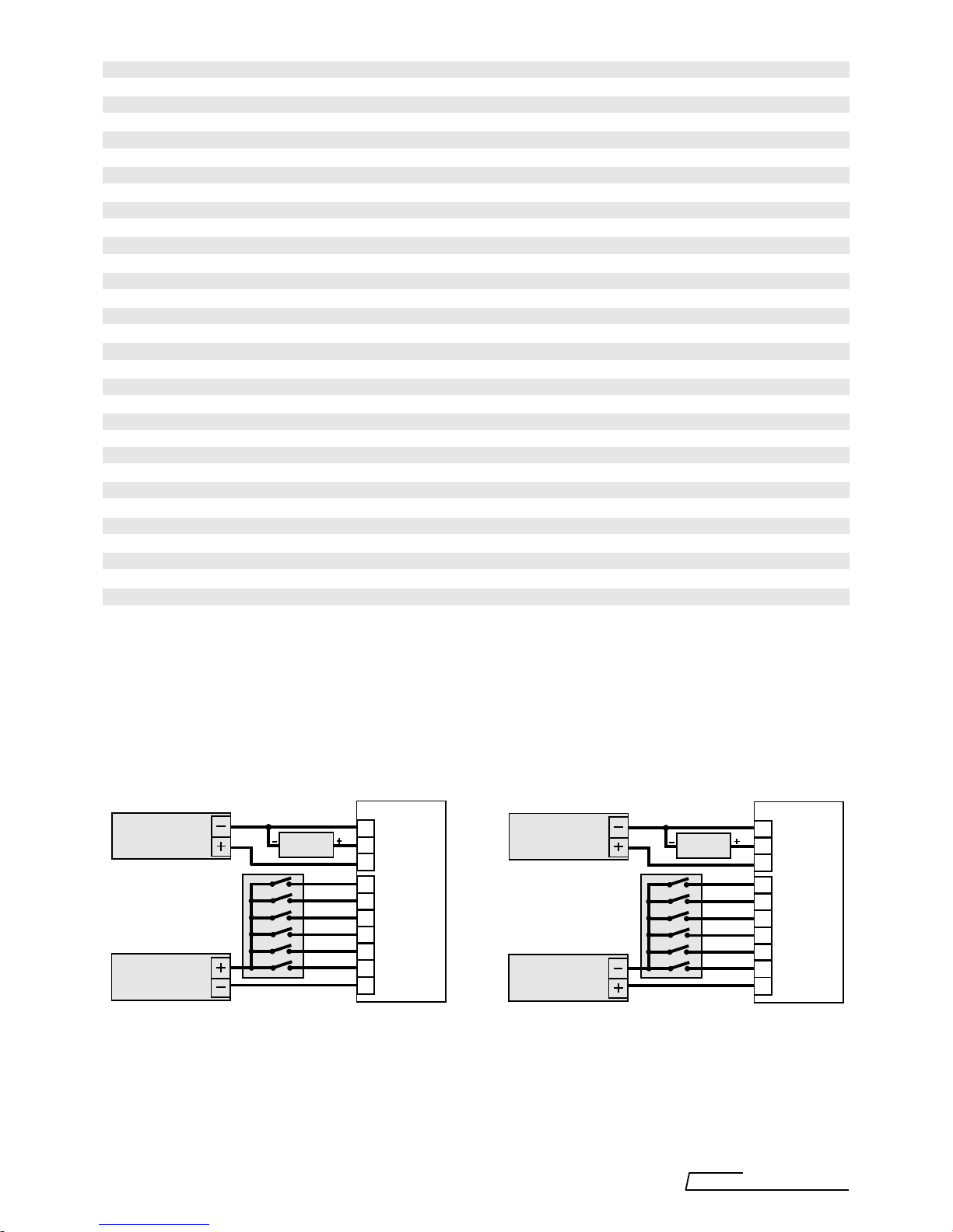
TW-DA Connection Examples.
Common '0V' Input. Common '+V' Input.
TW-DA Specifications.
Digital Inputs 6 Opto-Isolated Inputs with LED Indication for each Input.
Note: All Inputs have one common that can be connected to '0V' or '+V'.
Input Voltage 6~30Vdc.
Threshold Voltage 5.5V Typical.
Load @ 6V 1mA per Channel Typical.
@ 12V 4mA per Channel Typical.
@ 20V 8mA per Channel Typical.
@ 24V 9mA per Channel Typical.
Code Binary. N.O. Contact = '0', N.C. Contact = '1'.
Analogue Outputs
- Voltage Ranges 0~10V,2~10V.
- Output Drive 5mA Maximum. (2k@ 10V.)
- MilliAmp Ranges 0~20mA, 4~20mA
- Output Drive 10V Maximum. (500@ 20mA.)
Resolution From 2 to 6 bits. (4 to 64 steps.)
PowerSupply 24Vdc±6Vdc. LED Indication of Power Supply.
Current Usage - 20mA O/P 40mA Typical at 24Vdc P/S. (No allowance for Digital Inputs.)
- 10V O/P 22mA Typical at 24Vdc P/S. (No allowance for Digital Inputs.)
Accurate to Selected Resolution <±1% FSO Typical.
Linearity&Repeatability <±1% FSO Typical.
Ambient Drift <±0.02%/C FSO Typical.
EMC Compliances Emissions EN 55022-A. Immunity EN 50082-1, <1% Effect FSO Typical.
Isolation Test Voltages Digital Inputs to Analogue Input/Outputs: 1600Vdc for 1min.
Operating Temperature 0~70C.
Storage Temperature -20~80C.
OperatingHumidity 5~85%RH Max. Non-Condensing.
Construction DIN & EN Rail Mount Enclosure.
Dimensions L=90mm, W=78mm, H=45mm.
Weight 180g (Includes Packaging).
Product Liability. This information describes our products. It does not constitute guaranteed properties and is not intended to affirm the suitability
ofaproductforaparticularapplication.Duetoongoingresearchanddevelopment,designs,specifications,anddocumentationaresubjecttochange
without notification. Regrettably, omissions and exceptions cannot be completely ruled out. No liability will be accepted for errors, omissions or
amendments to this specification. Technical data are always specified by their average values and are based on Standard Calibration Units at 25C,
unless otherwise specified. Each product is subject to the ‘Conditions of Sale’.
Warning:Theseproductsarenotdesigned for use in,andshouldnotbeusedforpatientconnectedapplications.Inanycriticalinstallation
an independant fail-safe back-up system must always be implemented.
13.07-2
0V
OUT
24V
B1 (LSB)
B2
B4
B8
B16
B32 (MSB)
COM
TW-DA
10
9
8
7
6
5
4
3
2
1
6~30Vdc
Power Supply
24Vdc
Power Supply Indicator,
PLC, etc.
0V
OUT
24V
B1 (LSB)
B2
B4
B8
B16
B32 (MSB)
COM
TW-DA
10
9
8
7
6
5
4
3
2
1
6~30Vdc
Power Supply
24Vdc
Power Supply Indicator,
PLC, etc.
Note 1. N.O. Contact is '0'
N.C. Contact is '1'
Note 2. The COM of the inputs can connected to the +ve or the -ve of the input power supply.
Note 3. Solid state outputs are recommended for powering the digital inputs. If electro-mechanical relays are used
contact bounce may cause momentary false outputs.
Note 4. The same power supply can be used to power up both the input and output of the TW-DA. Note that this will
however void the isolation between input and output.
}Code is Binary.
Digital Outputs
from a PLC,
Controller, etc.
Intech
INSTRUMENTS LTD
www.intech.co.nz
13.07-3
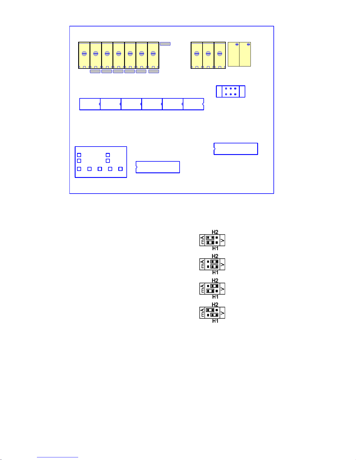
TW-DA Programming.
Selecting the Analogue Output.
Refer to the picture above for the location of the Headers on the PCB.
For 4~20mA output place the jumpers in the following positions:
For 0~10V output place the jumpers in the following positions:
For 0~20mA output place the jumpers in the following positions:
For 2~10V output place the jumpers in the following positions:
Selecting the Number of Digital Inputs.
Using 2 Digital Inputs gives 4 output steps: 33.3% per step. Use B32 for MSB, & B16 for LSB.
Using 3 Digital Inputs gives 8 output steps: 14.3% per step. Use B32 for MSB, & B8 for LSB.
Using 4 Digital Inputs gives 16 output steps: 6.67% per step. Use B32 for MSB, & B4 for LSB.
Using 5 Digital Inputs gives 32 output steps: 3.22% per step. Use B32 for MSB, & B2 for LSB.
Using 6 Digital Inputs gives 64 output steps: 1.59% per step. Use B32 for MSB, & B1 for LSB.
MSB = Most significant bit. LSB = Least significant bit.
Calibrating the TW-DA to the Required Ranges.
Note: To range the unit select the output range first.
1/ With no digital inputs active use the ZERO Pot to calibrate the 0% point.
Note: When adjusting 0~10V or 0~20mA ensure you do not overwind the ZERO Pot. A slight offset may be left.
Wind the zero reading down until it just makes it's minimum value.
2/ Activate the number of digital inputs to be used and use the SPAN Pot to calibrate the 100% point.
3/ Repeat 1/ and 2/ until no more adjustment is required.
4/ Do a mid point check to confirm your calibration.
5/ Label the unit with the number of digital inputs and the type of analogue output selected.
TW-DA PCB Layout - Location of H1 and H2 for Programming.
T1T2T3T4T5T6T7T8T9T10
0V OUT 24V POWER B1 B2 B4 B8 B16 B32 COM
ZERO
SPAN
.
TW-DA Rev 0
OUTPUT CALIBRATED
DIGITAL INPUTS
23456
4~20mA
0~20mA 0~10V
2~10V
H1
H2
mA
V

The Proper Installation & Maintenance of TW-DA.
All power and signals must be de-energised before connecting any wiring, or altering any Jumpers or Dip Switches.
MOUNTING.
(1) Mount in a clean environment in an electrical cabinet on DIN or EN rail.
(2) Do not subject to vibration or excess temperature or humidity variations.
(3) Avoid mounting in cabinets with power control equipment.
(4) TomaintaincompliancewiththeEMCDirectives,theTW-DAmustbemountedinafullyenclosed,metal,electrical
cabinet. The cabinet must be properly earthed, with appropriate input / output entry points, cabling and filtering.
WIRING.
(1) Allcables should begood quality overallscreened INSTRUMENTATION CABLEwith the screenearthed atone
endonly.
(2) Signal cables should be laid a minimum distance of 300mm from any power cables.
(3) For 2 wire current loops and 2 wire voltage signals or 2 wire current signals, Austral Standard Cables B5102ES
is recommended. For 3 wire transmitters Austral Standard Cables B5103ES is recommended.
(4) It is recommended that you do not ground current loops and use power supplies with ungrounded outputs.
(5) Lightning arrestors should be used when there is a danger from this source.
(6) Refer to diagrams for connection information.
COMMISSIONING.
(1) Once all the above conditions have been carried out and the wiring checked apply power to the TW-DA
loop and allow five minutes for it to stabilize.
(2) Take a low (approx. 10%) and high (approx. 90%) reading of the variable being measured by the transducer
supplying the signal to the TW-DA, and ensure that this agrees with the level being indicated by the PLC or
indicator, etc., that the TW-DA is connected to. Adjust for any difference using the Zero & Span Pots in the top
of the TW-DA enclosure with a small screwdriver, until the two levels agree. (Clockwise to increase the output
reading and anticlockwise to decrease the output reading.)
MAINTENANCE.
(1) Repeat (2) of Commissioning.
(2) Do it regularly - at least once every 12 months.
13.07-4 TW-DA 010212.p65
Intech
INSTRUMENTS LTD
www.intech.co.nz
Christchurch Ph: +64 3 343 0646
Auckland Ph: 09 827 1930
Email: [email protected]
Table of contents
Other Intech Media Converter manuals


