INTECNO BLD07-IT User manual
D.C. BRUSHLESS
MOTORS DRIVE
BLD07-IT
Service Manual
INTECNO s.r.l.
Via Caduti di Sabbiuno n. 9/E
40011 Anzola Emilia (BO) - Italy
tel. 051.19985350 fax 051.19985360
www.intecno-srl.com

Service manual for Brushless DC motor drive. Model BLD07-IT ___Versione 02/18
2
INDEX
Description
Page
Safety and note
3
General characteristics
4
Size
5
Drive and connector Layout
6
Power connection
7
Signal connection
9
Output
10
Trimmer, Dip switch and LEDs
11
General description and how to size the power supply
13
Warnings, recommendations and maintenance
14
Diagnostic and trouble shooting
15
Guidelines for correct installation and CE declaration of conformity
16

Service manual for Brushless DC motor drive. Model BLD07-IT ___Versione 02/18
3
SAFETY AND NOTE
Users must take care that motion control equipment is capable of producing high forces and rapid movement
so they must be used with attention, especially during the application program’s development.
This motion control equipments are sold as end-users products to be installed only by skilled personnel, in
accordance with all local safety laws and regulations. The device has to be enclosed such that any part is not
be accessible while the system is powered on.
We strongly recommend to follow these recommendations in order to avoid wrong uses of the equipment
that may make useless all the protections provided by the device.
Please read these notes carefully before powering up the drive:
It is very important to meet all applicable safety requirements during installation and operating of any motion
control equipment. Any installer has to assume the responsibility to ensure that it complies all the relevant
safety standards. Any installation, not meeting the safety requirements, may damage the equipment or injury
the user.
This motion control equipment should be handled, installed, setted-up and maintened only by competent
personnel expert and trained in the installation of motion control electronic equipment. Such technicians
should be aware of potential electrical and mechanical hazards. Shall never beliable or have any responsibility
if the products have been improperly stored, installed, used or maintened, or if the costumer has permitted
any unauthorized modifications, adjustments, and/or repairs to the products.
Simbols security standard:
Danger sign
:
All the circuits in the Drive are potential sources of severe electrical
shock, so follow these rules to avoide possible personal injury.
Power off the drive and wait until all the leds are turned off before
touching, removing, connecting or any other critical action.
Never disconnect any connectors before powering down the drive.
Please read this manual before using the drive!!!!
This manual replaces and cancels any previous edition
and revision
We reserve the right to make changes without notice.

Service manual for Brushless DC motor drive. Model BLD07-IT ___Versione 02/18
4
GENERAL CHARACTERISTICS
This converter is a bidirectional regenerative drive, suitable for driving three-phase brushless motors at low
voltage. PWM modulation with a carrier frequency of 20 kHz manages the power MOSFETs. Input voltage is
from battery or regulated power supply. Adjustable output voltage for the selection of the motor speed,
control and selection of direction, equipment ramps and the current limit.
Bidirectional regenerative drive
Power supply DC
3 Leds for diagnostic
Protected against short circuit, min / max voltage, shortage of Hall cells
Motor thermal protection lxt
Removable connectors (signals and power)
Analog speed Signal: 0 +10Vdc, frequency, PWM.
4 digital inputs, opto-isolated: Start/Stop, direction, 2 optional inputs
2 outputs NPN, alarms and running frequency
Acceleration ramp adjustment
General characteristics
Power Supply
24-36 Vdc
Nominal Current
7 A
Current regulation
3/4/5,5/7 A with dip switch or trimmer
Ambient temperature
0-40°C
Protection
Low voltage, high voltage, short circuit, shortage
of Hall signals. IxT
LEDs
Power ON, FAULT, IxT
Digital outputs
2 NPN open collector, max 50 V max 100 mA
Digital inputs
4 opto-isolated
Analog speed reference input
External analog signal 0-10 Vdc or speed
potentiometer 10 kOhm
Trimmer speed selection
On Board
Dip Switch of selection
4
IP
10
Mass (Kg)
0,25

Service manual for Brushless DC motor drive. Model BLD07-IT ___Versione 02/18
5
SIZE
Service manual for Brushless DC motor drive. Model BLD07-IT ___Versione 02/18
6
LAYOUT AND TERMINAL OF THE DRIVE
From right
Power connection:
+V = power supply, positive
GND = power supply, negative
U, V, W = power motor phases
HALL connector:
+12V= supply power of sensors
GND = negative for power of the sensors
H1 Hall U, H2 Hall V, H3 Hall W = the three phases of the hall sensors
Connector of potentiometer (or external analogue signal 0-10V):
GND, SIG, +10V pins of the potentiometer. The cursor (variable pin) goes to the
terminal SIG.
Connector I/O:
FREQ= square wave output proportional to speed, NPN open collector signal.
FAULT = alarm output, NPN open collector signal.
F/R = selector of the direction of the rotation.
R/S = start/stop operation command
GND= common for the commands of R/S and F/R
IN1, IN2 = not used
LD3
LD2
LD1
IN1
IN2
GND
R/S
F/R
+12
FAULT
FREQ
GND
SIG
+10V
GND
+12V
H1 HALL U
H2 HALL V
H3 HALL W
+V
GND
U
V
W
OFF
ON
1
2
3
4
TR2
TR1

Service manual for Brushless DC motor drive. Model BLD07-IT ___Versione 02/18
7
DIAGRAM CONNECTIONS OF POWER SUPPLY AND
MOTOR
Connections for motors: BL012.240 –BL018.240 –BL025.24E –
BLS022.240 –BL032.240 –BLS043.240 –BL043.240
SUPPLY POWER:
lead the positive on +V, and the negative to GND.
Be careful, not to reverse the polarity, risk of damage to the board.
MOTOR POWER:
The phases, U = yellow, V = red, W = black.
HALL MOTOR:
The phases, +12V = red, HU= blue, HV = green, HW = white, GND = black
This color sequence must be followed.
LD3
LD2
LD1
IN1
IN2
GND
R/S
F/R
+12
FAULT
FREQ
GND
SIG
+10V
GND
+12V
H1 HALL U
H2 HALL V
H3 HALL W
+V
GND
U
V
W
OFF
ON
1
2
3
4
TR2
TR1
Motor HALL
Sensors
HALL MOTORE
Motor
Power
Power
Supply

Service manual for Brushless DC motor drive. Model BLD07-IT ___Versione 02/18
8
DIAGRAM CONNECTIONS OF POWER SUPPLY AND
MOTOR
Connections for motor: BL005.240
SUPPLY POWER:
lead the positive on +V, and the negative to GND.
Be careful, not to reverse the polarity, risk of damage to the board.
MOTOR POWER:
The phases, U = green, V = red, W = black.
HALL MOTOR:
The phases, +12V = yellow, HU= blue, HV = orange, HW = brown, GND = white.
This color sequence must be followed.
LD3
LD2
LD1
IN1
IN2
GND
R/S
F/R
+12
FAULT
FREQ
GND
SIG
+10V
GND
+12V
H1 HALL U
H2 HALL V
H3 HALL W
+V
GND
U
V
W
OFF
ON
1
2
3
4
TR2
TR1
Motor HALL
Sensors
HALL MOTORE
Motor
Power
Power
Supply

Service manual for Brushless DC motor drive. Model BLD07-IT ___Versione 02/18
9
SIGNAL CONNECTION
R/S
F/R
Connect the potentiometer as shown in diagram. Be careful: the cursor (variable pin) must be connected to
SIG. in case of analog power supply 0/+10 V, the reference goes to GND and the signal to SIG.
Closing the R/S terminal to GND for managing the run and stop operations.
Closing the F/R terminal to GND to determine the direction selection.
DANGER:
This command forces the run in reverse direction immediately without the needing to open
and close again the R/S.
LD3
LD2
LD1
IN1
IN2
GND
R/S
F/R
+12
FAULT
FREQ
GND
SIG
+10V
GND
+12V
H1 Hall U
H2 HALL V
H3 HALL W
+V
GND
U
V
W
OFF
ON
1
2
3
4
TR2
TR1
SPEED POT
Service manual for Brushless DC motor drive. Model BLD07-IT ___Versione 02/18
10
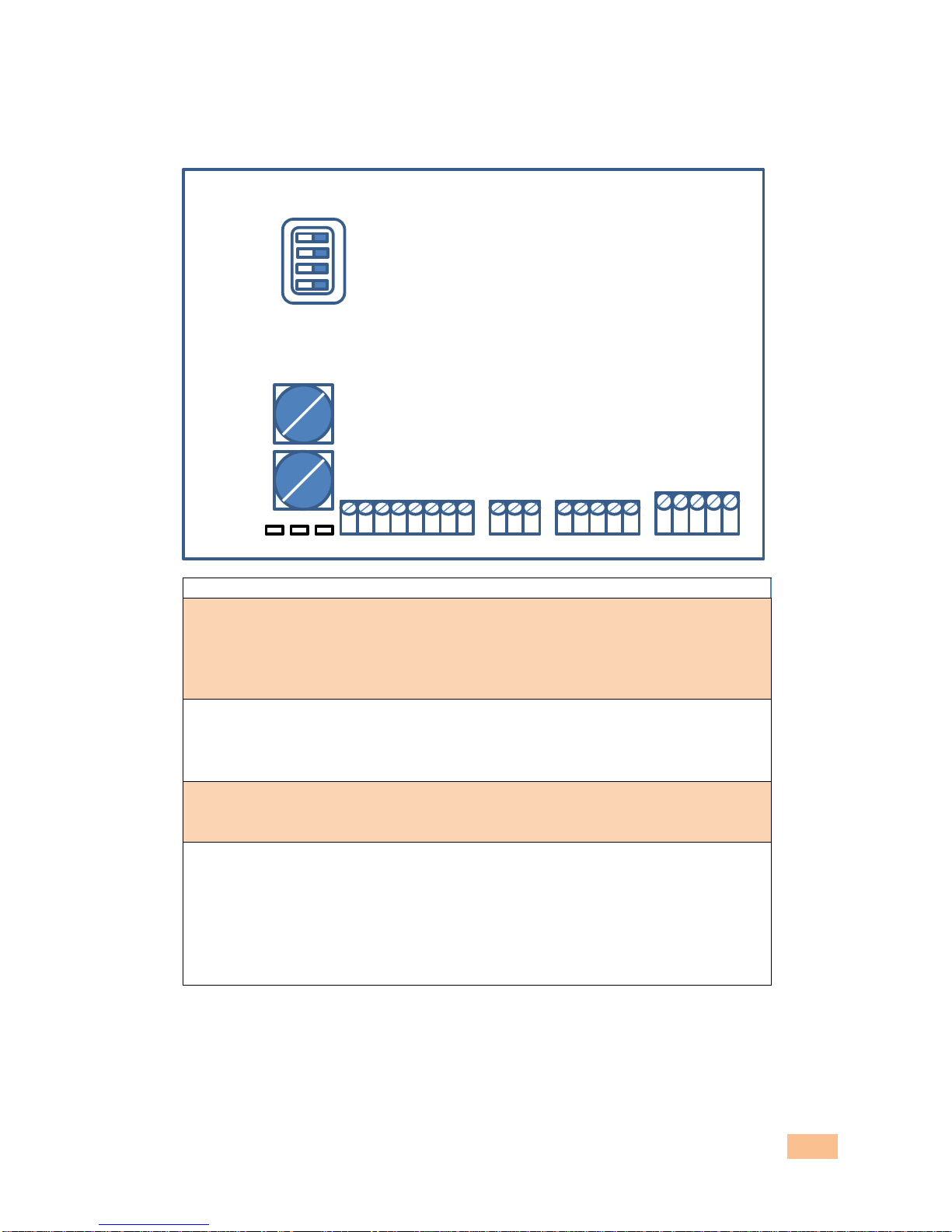
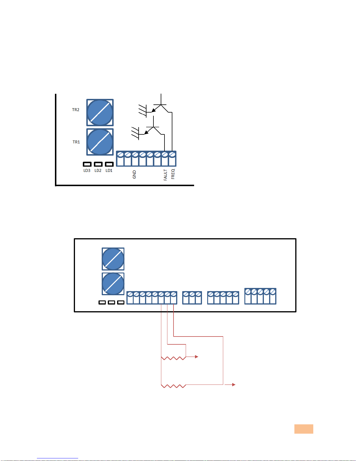
OUTPUT
There are two NPN outputs open collector. Can be used as open collector outputs (if equipped with PLC which
accepts the NPN output), or with a resistance R = 10 KOHM (one for each output) to get a voltage signal. 50
V & 100 mA NPN outputs, MAX.
Note: The FAULT output is normally closed. It opens when an alarm happens. In the case of the pull up
resistor, the alarm output is a voltage (+12 Vdc signal).
The signal is output at the point of the arrow (see diagram below).
+12V Fault
+12V Freq
LD3
LD2
LD1
IN1
IN2
GND
R/S
F/R
+12
FAULT
FREQ
GND
SIG
+10V
GND
+12V
H1 HALL U
H2 HALL V
H3 HALL W
+V
GND
U
V
W
TR2
TR1
R = 10 KΩ
R = 10 KΩ

Service manual for Brushless DC motor drive. Model BLD07-IT ___Versione 02/18
11
DIP SWITCH, TRIMMER and LEDs
Motor
Poles
Dip Switch 4
Nom. Current [A]
Motor Voltage [V]
BL 005.240
4
Off
1,0
24
BL 012.240
8
On
3,5
24
BL 018.240
8
On
5
24
BL 025.24E
8
On
6,6
24
BL 032.240
4
Off
5
24/36
BL 043.240
4
Off
6,8
24/36
BLS 022.240
4
Off
3,7
24/36
BLS 043.240
4
Off
6,0
24/36
Dip switch
Descrizione
1 Selecting input for speed reference
OFF = speed controlled by on board trimmer (TR1).
ON = speed controlled by external potentiometer or 0-10V
analog signal
2 Speed fine tuning function
OFF = enabled
ON = disabled
3 Acceleration/deceleration selection
OFF = fast ramps (about 0.1 seconds)
ON = slow ramps (about 1.0 seconds)
4 Motor polarity selection
OFF = 4 poles motors
ON = 8 poles motors
LD3
LD2
LD1
IN1
IN2
GND
R/S
F/R
+12
FAULT
FREQ
GND
SIG
+10
V
GND
+12
V
H1 HALL U
H2 HALL V
H3 HALL W
+V
GND
U
V
W
OF
F
ON
1
2
3
4
TR2
TR1

Service manual for Brushless DC motor drive. Model BLD07-IT ___Versione 02/18
12
Use of TRIMMER for current limitation (TR2):
The trimmer limits the supply of the current, in order to match
the current to the motor’s rated one. To set correctly: adopt a
current amperometer (to be placed on the positive supply), rotate
fully counterclockwise this trimmer load the motor, up to read the
rated value on the amperometer. Afterwards, turn the trimmer
clockwise until you see a light flashing but persistent.
Indicative positions of the trimmer:
3A
4A
5.5A
7A
Trimmers
TR1 = speed selection trimmer (it rises in clockwise rotation)
TR2 = trimmer for current limitation (it rises in counter-clockwise rotation)
LEDs
LED1 = green, POWER ON (voltage is present)
LED2 = red, active alarm
LED3 = yellow, it has two functions: during normal operation it indicates the current limit. In case of alarm
blinks according to precise coding to show the type of alarm active. (see pag. 15)
There are on board other two LEDs that light up at the closing of the contacts of R/S and F/R.
LD3
LD2
LD1
IN
1
IN2
GND
R/S
F/R
FAULT
FREQ
TR2
TR1

Service manual for Brushless DC motor drive. Model BLD07-IT ___Versione 02/18
13
GENERAL DESCRIPTION
Supply the board to pins (+ V, GND) with stabilized voltage 24 Vdc or 36 Vdc depending on the motor.
Connect the pins of the motor to the U-V-W power contacts in the given order. WARNING: RESPECT THE
SEQUENCE!
Connect the Hall motor contacts signal pins H1 Hall U - H2 Hall V - H3 Hall W in the given order: WARNING:
RESPECT THE SEQUENCE.
Run command: close with an external contact pin R / S to GND. OPEN to command a STOP.
Selection of the direction: close with an external contact pin F / R to GND. NOTE: This contact produces
immediate reversal of motion and does not wait for a new run command. WARNING!
FAULT output: it switches due to an alarm, to show to the user or the PLC the status of the drive. Using
a pull-up resistor (as per this manual) is possible to switch from the open collector signal (=simple open
or closed contact) to a voltage signal: 0 Vdc = ready; 12 Vdc = alarm on.
Output FREQ (reference motor speed): this contact gets out a frequency signal proportional to the motor
speed. It is a signal with a duty cycle of about 50% and resolution 6 / rev. Using a pull-up resistor (as per
this manual) is possible to switch from the open collector signal (=simple open or closed contact) to a
voltage signal. 0 Vdc ÷ 12 Vdc.
Speed reference: it gives a speed reference to the motor, that is, how fast you want it to run. The
selection of Dip 1 is used to control the speed via the TR1 trimmer on board. In this way any external
devices is requested. Dip 1 allows you also to select the reference from an external potentiometer by
potentiometer from 10 KOhm. Or analog signal 0-10 Vdc. The signal is proportional, that is, increase the
signal to increase the speed of the motor.
HOW TO SIZE THE POWER SUPPLY
The drive requires stabilized DC voltage.
The level is 24 or 36 Vdc. The selection of the voltage level depends on the nominal value in the motor plate.
Please remember that reducing voltage the motor becomes depowered.
You can supercharge a few volts, especially if you are concerned that there is a significant drop on the supply
lines.
Two solutions are possible:
• stabilized power supply
• transformer, bridge rectifier, smoothing capacitor
The solution with the transformer, bridge rectifer, smoothing capacitor is more suitable in applications with
regenerative loads.
Fuses:
Recommended size is 2 times the rated current of the motor fuse with delayed trip and in any case not exceed
12 A, to be assembled in series with the supply.

Service manual for Brushless DC motor drive. Model BLD07-IT ___Versione 02/18
14
WARNINGS, RECOMMENDATIONS AND MAINTENANCE
Power the driver only when the motor has been mounted safely. Beware of moving parts: DANGER.
Pay attention to the key of the motor, in case you run the motor.
Do not reverse the power polarity of the drive: risks damaging.
You must follow the color sequence of the power and signal cables, as per this manual. Caution:
danger of damaging.
Apply the drive possibly vertically. It is suggested to mount on a metal base plate to improve heat
dissipation. Keep the drive in an electrical panel, reasonably ventilated, if possible, or at least with
open space all around.
Avoid dusty and humid environments.
The drive is NOT suitable for use in explosive or dangerous atmosphere.
It is not recommended to cut the line between drive and motor, and if it must be done, open the line
when motor is not running. The risk is to damage the power transistors.
Avoid contamination with dirt, dust, water and metal debris.
The drive is sensitive to electrostatic discharge
For questions or uncertainties, please contact Intecno srl.
MAINTENANCE:
after a long period of storage, it is recommended to power the drive with low load for a few minutes.
In case of replacement of the motor verify the DIP Switch settings and the current limit.

Service manual for Brushless DC motor drive. Model BLD07-IT ___Versione 02/18
15
DIAGNOSTIC AND TROUBLE SHOOTING
Alarms mean certain dangerous conditions (for the drive or the mechanism) that the drive is able to verify
and, in the case, to interrupt operation.
LED 2 (red) indicates alarm in progress, while the LED 3 (yellow), is used to identify the type of alarm;
depending on the number of flashes it indicates a different problem.
N° Flashes
Description
Possible solutions (in order)
1
The sequence of the Hall
signals is not correct and
the drive is not able to
determine the correct
sequence of the phases.
• Check wire (colors) sequence of the Hall, they must be
exactly as per the manual.
• Check that the cables are properly inserted into the
connector.
• Contact technical department Intecno srl.
2
Short circuit. The drive is
delivering the current in
an excessive way.
• Recheck that the power and signal cables are properly
connected (according to the colors shown in this manual).
• Check that the motor is free to rotate.
• Check that the load on the motor does not exceed the
motor nameplate data (including radial loads of potential
pulleys and belts).
• Disconnect the motor and try to run without the motor,
if the alarm persists.
• Contact technical department Intecno srl.
3
too low voltage level (<18
V)
• Check the quality of power source.
• Check the voltage level of the source.
• Make sure the power supply is adequate.
• Ensure proper cable section and length.
4
too high level voltage (>
55V)
• Check the voltage level of the power source.
• Check that the load is not inertial one, in which case make
longer the deceleration ramp.
5
Sudden motor block
• Check the mechanics of the application
6
Power failure Hall
• Check the connection of the signals and power Hall and
the connection of the connector.
Problematic Vibrations:
Vibrations
Possible solutions
the motor vibrates visibly and it also absorbs a
lot of current even together with an empty
motor.
carefully check the sequence of the signal cables and
power, as it is in the manual.

Service manual for Brushless DC motor drive. Model BLD07-IT ___Versione 02/18
16
GUIDELINES FOR CORRECT INSTALLATION
The BLD07IT drive is a product classified in Category C3.
The product complies with EC rules if it is subject to the following guidelines assembly:
•installation of an atmospheric discharge device on the power line of the type approved according
to EN 61643-11 and EN 61643-1 with discharge for at least 2.5 kV impulse voltage (suppressor
lightning).
•Earth the heatsink at the point indicated by printed symbol; it’s done to eliminate static discharge,
which can damage the drive.
•Maximum length of Power supply cables 3 m.
•Maximum lenght of the signal and connection cables 3 m.
CE DECLARATION OF CONFORMITY
The BLD07IT complies with the essential requirements of Directive:
EMC 2014/30/UE
ROHS 2011/65/UE
Applicable to the product. Furthermore, the object of the declaration described above is in conformity with
the relevant Union harmonization legislation:
EN 61800-3:2004 +A1:2012
Table of contents


