Integral LED ILCTDMX001 User manual
INTEGRAL LED DMX512 DECODER ILCTDMX001
WARNING
DO NOT CONNECT THE DMX512 DECODER DIRECTLY TO A MAINS SUPPLY
THE DMX512 DECODER MUST ONLY BE CONNECTED TO A SUITABLE DC12V-36V LED DRIVER
SWITCH OFF POWER AT THE MAINS BEFORE INSTALLING THE PRODUCT
PLEASE READ BEFORE USE
IP20
IMPORTANT NOTICE
1. INTRODUCTION
2. PARAMETER
• Switch OFF power at the mains before installing the product.
• This product should be installed according to the instructions in this guide and by a qualied electrical installer.
• All electrical work must be completed in accordance with the latest IET wiring regulations (formally IEE) for
the UK or in accordance with all applicable regulations and laws in the country in which it is being installed.
• Always disconnect or switch o the power supply before making any adjustment to the wiring.
• Observe the operating temperature of the product: Max Tc 75°C.
• Limited 5 Year Warranty. This DMX512 Decoder is for indoor use only. Improper installation, abuse or miss-
powering of the decoder or failure to use the decoder for its intended use will void the warranty. Proof of
purchase is required for all returns. Your statutory rights remain unaected.
Please see www.integral-LED.com/warranty.
Questions? Please contact you supplier or see www.integral-LED.com
The Integral ILCTDMX001 DMX512 Decoder is designed as standard DMX512 compliant control interface,
receiving DMX512 signal and distributing to LED strip products with constant voltage (DC 12V-36V). You
will be able to set up the DMX address as your preference and the address is shown on the 3-digit display.
ILCTDMX001 DMX512 Decoder is compatible with a standard DMX512 master controller.
• Input Voltage: DC12V–DC36V, Constant Voltage
• Output Current: Max 32A, 8Ax4CH
• Output Power: Max 384W (12V) / 768W (24V) /
1152W (36V)
• IP Rating: IP20
• Ambient Temperature: Ta -20°C to +50°C.
• Operating Temperature: Max Tc 75°C.
• Dimensions: L170×W59×H29 (mm)
• Weight (N.W.): 215g
3. OPERATING INSTRUCTIONS
DC INPUT
12/36VDC
V+
V-
V+
G-
R-
OUTPUT
CH1
2
B-
3
B-
3
W-
4
DMX 512 D ec od er
GND
DMX+
DMX-
DMX+
DMX-
0-90-5 0-9
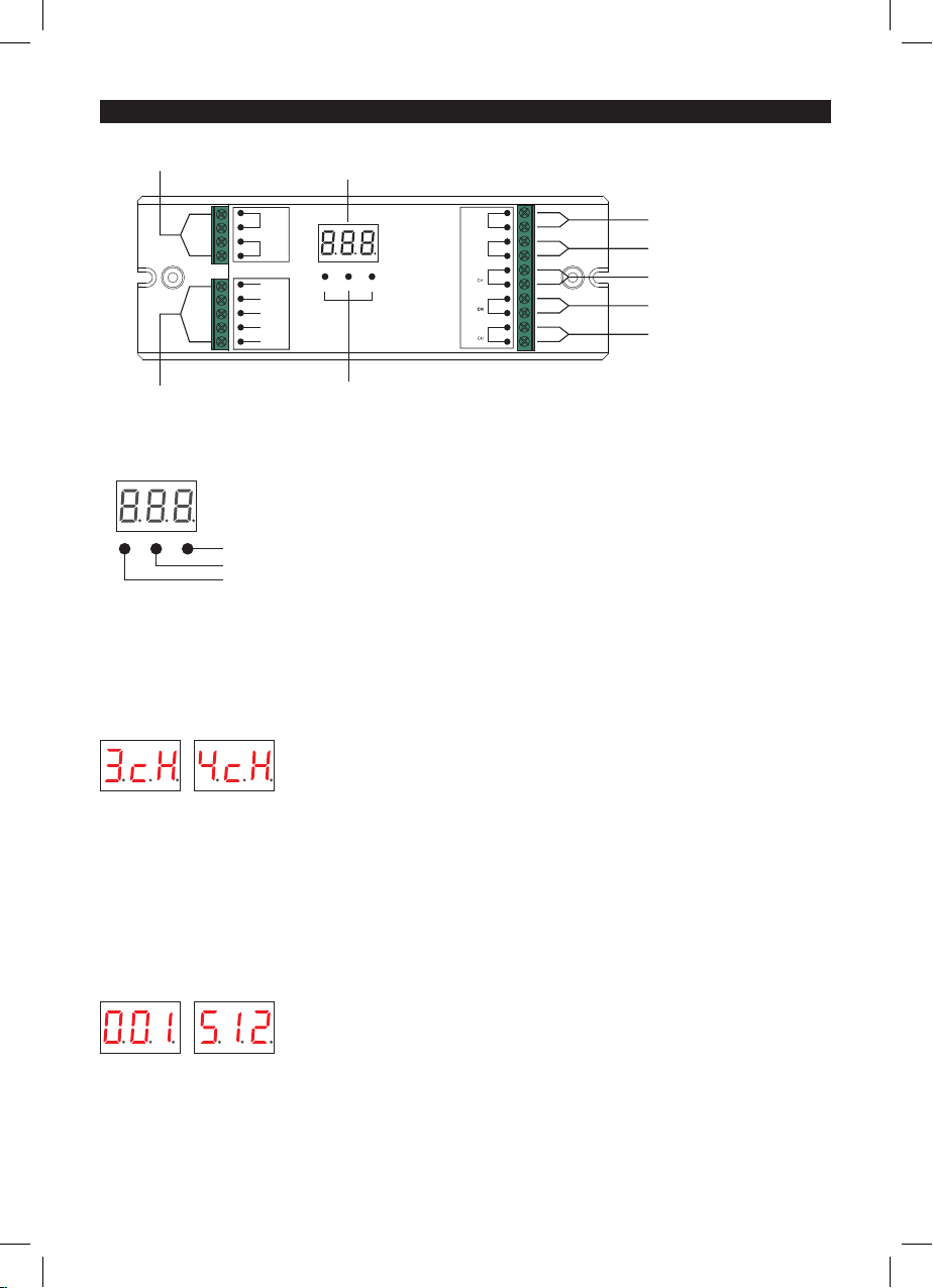
DC power input
Manual set button
Digital display
CH 1:R/WW output(-)
CH 2:G/CW output(-)
CH 3:B/WW output(-)
Common Anode Output(+
)
CH 4:W/CW output(-)
2 groups DMX512
signal input & output
Button 3
Button 2
Button 1 (Image 1)
(Image 3)
(Image 2)
Digital Display Setup
Press the buttons to set preferred channel and DMX512 address. Press button 1 to set“hundreds digit”, press
button 2 to set “tens digit” and press button 3 to set “unit digit” (Image 1).
Set Up DMX Address
To set up DMX512 address, press button 1 for at least 2 seconds until digital display ashes. Press button 1
to set “hundreds digit”, press button 2 to set “tens digit” and press button 3 to set “unit digit”. For example,
to set up DMX address to 001, press button 1 to choose 0, press button 2 to choose 0 and press button 3 to
choose 1. After the display shows 001 address, press any button for at least 2 seconds to conrm the address.
Set Up Channel
To set up channel, press button 2 and button 3 simultaneously for at least 2 seconds until digital display
ashes. Then press button 1 to select the numbers of channels (1 channels, 2 channels, 3 channels or 4
channels). 3 means there will be total 3 channels and 4 means there will be total 4 channels (Image 2).
The factory setting is 4 channels. After choosing the numbers of channels, press any button for at least 2
seconds to conrm selection.

4. WIRING DIAGRAM
Example of Scenario
Address is set to 001
• When set up as 1CH (1 channel), all 4 channels will be the same address 001. Then 4 channels will be
controlled at the same time, suitable for single colour led strips (when 4 single colour led strips are
connected to control together).
• When set up as 2CH (2 channels), channel 1 and channel 3 will be the same address 001, channel 2 and
channel 4 will be 002. Then channel 1 and 3 will be controlled at the same time, and channel 2 and 4 will
be controlled at the same time, suitable colour temperature changing led strips.
• When set up as 3CH (3 channels), channel 1,2,3 will be address 001,002,003, and channel 4 address is also
001. Then channel 1, channel 2 and channel 3 are controlled separately and channel 4 is not required,
suitable for RGB led strip.
• When set up as 4CH (4 channels), channel 1, 2, 3,4 will be address 001, 002,003,004. Then each channel can
be controlled seperately, suitable for RGBW led strip or single colour led strips (when 4 single colour led
strips are connected to control seperately).
DMX512
Master
AC Power
50/60Hz
12V/24V/36V
CV PSU
L
N
G
V+
V-
OUTPUT
INPUT
V+ V+
R- R-
G- G-
B- B-
W- W-
V+ V+
1- V-
2- V-
3- V-
4- V-
V+ V+
WW WW
CW CW
WW WW
CW CW
DC INPUT
12/36VDC
V+
V-
V+
G-
R-
OUTPUT
CH1
2
B-
3
B-
3
W-
4
DMX512 Decoder
GND
DMX +
DMX -
DMX +
DMX -
0-90-5 0-9
DC INPUT
12/36VDC
V+
V-
V+
G-
R-
OUTPUT
CH1
2
B-
3
B-
3
W-
4
DMX512 Decoder
GND
DMX +
DMX -
DMX +
DMX -
0-90-5 0-9
DC INPUT
12/36VDC
V+
V-
V+
G-
R-
OUTPUT
CH1
2
B-
3
B-
3
W-
4
DMX512 Decoder
GND
DMX +
DMX -
DMX +
DMX -
0-90-5 0-9
RGBW LED Strip
(Typically set up as 4CH)
Single Colour LED Strip
(Typically set up as 1CH, 2CH, 3Ch or 4CH)
Colour Temperature
Changing LED Strip
(Typically set up as 2CH)
www.integral-led.com
WASTE ELECTRICAL PRODUCTS SHOULD NOT BE DISPOSED OF WITH
HOUSEHOLD WASTE. PLEASE RECYCLE WHERE FACILITIES EXIST. CHECK
WITH YOUR LOCAL AUTHORITY FOR RECYCLING ADVICE.
Integral LED is a division
of Integral Memory plc:
Unit 6 Iron Bridge Close,
Iron Bridge Business Park,
London, NW10 0UF, UK


