Speco OSW8T User manual

User Manual
8 Channel TV/Analog Encoder
OSW8T
Please read this manual carefully before operating the unit and keep it for further reference

IP Camera User Manual
1.
Electrical safety
All installation and operation here should conform to local electrical safety codes.
Use a certified/listed 12VDC Class 2 power supply only.
Please note: Do not connect two power supplying sources to the device at the same time; it may result in device damage! The
product must be grounded to reduce the risk of electric shock.
Improper handling and/or installation could run the risk of fire or electrical shock.
2.
Environment
Heavy stress, violent vibration or exposure to water is not allowed during transportation, storage and installation.
This product should be installed in a cool, dry place away from direct sunlight and heat sources.
Do not install the product in extreme temperature conditions.
Do not expose the device and the connected camera to electromagnetic radiation.
Do not block any ventilation openings.
Do not allow water and liquid intrusion into the camera and the device.
3.
Operation and Daily Maintenance
Please shut down the device and then unplug the power cable before you begin any maintenance work.
Always use the dry soft cloth to clean the device. If there is too much dust, use a cloth dampened with a small quantity of neutral
detergent. Finally use the dry cloth to clean the device.
The grounding holes of the product are recommended to be grounded to further enhance the reliability of the product.
Important Safeguards and Warnings

IP Camera User Manual
Warning
This device should be installed by qualified personnel only.
All the examination and repair work should be done by qualified personnel.
Any unauthorized changes or modifications could void the warranty.
Statement
This guide is for reference only.
Product, manuals and specifications may be modified without prior notice. Speco Technologies reserves the right to modify these
without notice and without incurring any obligation.
Speco Technologies is not liable for any loss caused by improper operation.
Regulatory Information
1.1 F
CC
c
ond
i
t
i
ons
:
This device complies with part 15 of the FCC Rules. Operation is subject to the following two conditions:
•
This device may not cause harmful interference
•
This device must accept any interference received, including interference that may cause undesired operation.
1.2 F
CC
c
omp
li
a
n
c
e
:
This equipment has been tested and found to comply with the limits for a digital device, pursuant to part 15 of the FCC Rules. These
limits are designed to provide reasonable protection against harmful interference. This equipment generate, uses and can radiate radio
frequency energy and, if not installed and used in accordance with the instruction manual, may cause harmful interference to radio
communication. However, there is no guarantee that interference will not occur in a particular installation. If this equipment does cause
harmful interference to radio or television reception, which can be determined by turning the equipment off and on, the user is
encouraged to try to correct the interference by one or more of the following measures:
•
Reorient or relocate the receiving antenna.
•
Increase the separation between the equipment and receiver.
•
Connect the equipment into an outlet on a circuit different from that to which the receiver is connected.
Note:
Before installation, check the package and make sure that all components are included.
Contact your rep or Speco customer service department immediately if something is broken or missing in the package.
Accessory Name
Amount
8 Channel Encoder Wall Mount Unit
1
Power Supply
1
CD
1

IP Camera User Manual
Regulatory Information ................................................................................................................................................................................................................3
1
Introduction ........................................................................................................................................................................................................................1
Welcome ......................................................................................................................................................................................................................................1
2
Web Access and Login.........................................................................................................................................................................................................2
2.1 LAN ......................................................................................................................................................................................................................................................................2
3
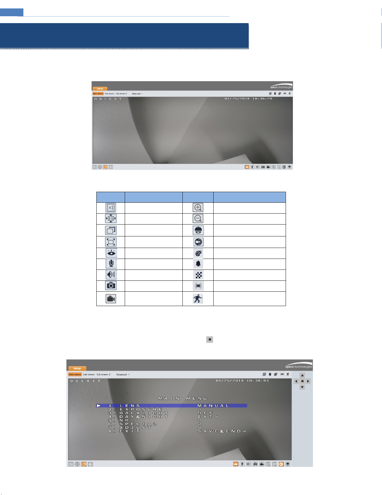
Live View .............................................................................................................................................................................................................................3
4
Device Configuration...........................................................................................................................................................................................................5
4.1 System Configuration........................................................................................................................................................................................................................................... 5
4.1.1 System Information ............................................................................................................................................................................................................................5
4.1.2 Date and Time.....................................................................................................................................................................................................................................5
4.1.3 Local Recording...................................................................................................................................................................................................................................5
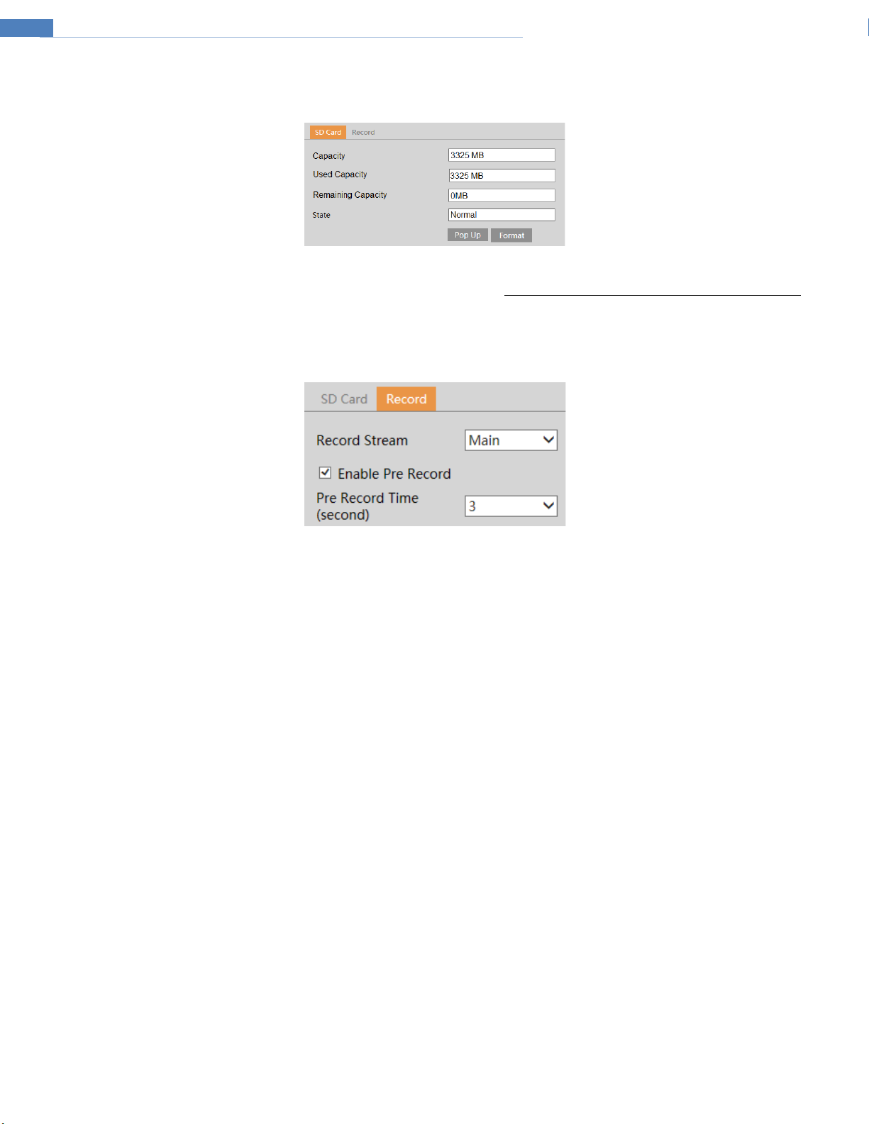
4.1.4 Storage ...............................................................................................................................................................................................................................................6
4.2 Video Configuration.............................................................................................................................................................................................................................................7
4.2.1 Image Configuration ...........................................................................................................................................................................................................................7
4.2.2 Video / Audio Setup............................................................................................................................................................................................................................8
4.2.3 OSD Configuration ..............................................................................................................................................................................................................................8
4.2.4 Privacy Mask.......................................................................................................................................................................................................................................9
4.2.5 Region of Interest Configuration......................................................................................................................................................................................................... 9
4.3 PTZ Configuration .............................................................................................................................................................................................................................................. 10
4.4 Event Setup........................................................................................................................................................................................................................................................ 11
4.4.1 Motion Detection ............................................................................................................................................................................................................................. 11
4.4.2 Alarm In (Sensor Input)..................................................................................................................................................................................................................... 12
4.4.3 Alarm Out ......................................................................................................................................................................................................................................... 13
4.4.4 Alarm Server..................................................................................................................................................................................................................................... 13
4.5 Analytics Configuration...................................................................................................................................................................................................................................... 14
4.5.1 Object Removal................................................................................................................................................................................................................................. 14
4.5.2 Abnormality...................................................................................................................................................................................................................................... 15
4.5.3 Line Crossing..................................................................................................................................................................................................................................... 16
4.5.4 Intrusion ........................................................................................................................................................................................................................................... 16
4.6 Network Setup................................................................................................................................................................................................................................................... 18
4.6.1 TCP/IP............................................................................................................................................................................................................................................... 18
4.6.2 Port...................................................................................................................................................................................................................................................18
4.6.3 DDNS ................................................................................................................................................................................................................................................ 19
4.6.4 SNMP................................................................................................................................................................................................................................................ 19
4.6.5 RTSP.................................................................................................................................................................................................................................................. 20
4.6.6 UPnP................................................................................................................................................................................................................................................. 20
4.6.7 Email.................................................................................................................................................................................................................................................21
4.6.8 FTP....................................................................................................................................................................................................................................................21
4.7 Security Configuration ....................................................................................................................................................................................................................................... 23
4.7.1 User Admin....................................................................................................................................................................................................................................... 23
4.7.2 Online User....................................................................................................................................................................................................................................... 24
4.7.3 Block and Allow Lists......................................................................................................................................................................................................................... 24
4.8 Maintenance Configuration ...............................................................................................................................................................................................................................24
4.8.1 Backup and Restore.......................................................................................................................................................................................................................... 24
4.8.2 Reboot.............................................................................................................................................................................................................................................. 25
4.8.3 Upgrade............................................................................................................................................................................................................................................ 25
4.8.4 Log....................................................................................................................................................................................................................................................25
5
Search................................................................................................................................................................................................................................26
5.1 Image Search ..................................................................................................................................................................................................................................................... 26
5.2 Video Search...................................................................................................................................................................................................................................................... 27
5.2.1 Local Video Search............................................................................................................................................................................................................................ 27
5.2.2 SD Card Video Search........................................................................................................................................................................................................................ 27
Appendix ....................................................................................................................................................................................................................................28
Appendix 1 Troubleshooting ......................................................................................................................................................................................................28
Table of Contents

IP Camera User Manual
1
Welcome
Thank you for purchasing this device!
Please read this manual carefully before operating the unit and retain it for future reference.
Should you require any technical assistance, please contact Speco Technologies Technical Support.
Main Features
•
Built-in PoE (Power over Ethernet)
•
Converts HD-TVI cameras (up to 2MP) and analog cameras to IP
•
H.265 and H.264 compression
•
12V DC power output for powering cameras (max 500mA)
•
UTC control support for accessing camera OSD menus and optical zoom/focus functions
•
Remote viewing support via web browser, mobile app, and VMS
Applications
Camera BNC OSW8T Network Web Browser
Camera BNC OSW8T Network NVR
Camera BNC OSW8T Network SecureGuard VMS/CMS
1 Introduction

IP Camera User Manual
2
The device settings can be accessed via a web browser through the LAN.
2.1 LAN
•
Access through IP Scanner
①Make sure that the device and the PC are connected on the same local network. The device is set to DHCP by default and will be assigned an IP
address by the DHCP server. Make sure that the local network has a DHCP server. Routers typically have a DHCP server built in.
②Install IP Scanner from the CD and run it after installation. IP Scanner is the tool for discovering the Speco IP devices on the local network.
③In the device list, the IP address, model number, and MAC address of each device will be listed. Select the applicable device and double click to open
up the web viewer. You can also manually enter the IP address in the address bar of the web browser.
The login interface is shown above. Default user name is admin and password is 1234. After logging in, follow directions to install applicable plug-ins for
viewing video.
2 Web Access and Login

IP Camera User Manual
3
The window below will be shown after logging in. Note: Make sure that a compatible camera is connected (HD-TVI up to 2MP and all analog cameras
are supported).
The following table describes the icons on the live view interface.
Icon
Description
Icon
Description
Original size of resolution
Digital zoom in
Fit (correct scale)
Digital zoom out
Auto (fill the window)
PTZ control (for external PTZ
enclosures)
Full screen (show video
only)
UTC control
Start/stop live view
Abnormal color indicator
Start/stop two-way audio
Abnormal clarity indicator
Enable/disable audio
Scene change indicator
Snapshot
Sensor alarm indicator
Start/stop local recording
Motion alarm indicator
•
All indicator icons above will flash in live view interface only when the corresponding events are enabled.
•
In full screen mode, to exit, double click on the mouse or press the ESC key on the keyboard.
To access the OSD of a camera, click on the UTC control button and press the button to open the OSD menu. Use the directional buttons to
navigate the menu.
3 Live View

IP Camera User Manual
4
A PTZ camera can be connected through the RS-485 interface. Click the PTZ icon to reveal the PTZ control panel.
The descriptions of the control panel are as follows:
Icon
Description
Icon
Description
Move upper left direction
Move upper right direction
Move up
Stop movement
Move left
Move right
Move lower left direction
Move lower right direction
Move down
Speed adjustment
Zoom out
Zoom in
Focus -
Focus +
Iris -
Iris +
Auto scan
Wiper
Light
Random scan
Group scan
Preset
Select preset and click to call the preset. Select and set the preset and then click to save the position of the preset. To delete a preset, select
the preset and click to delete it.

IP Camera User Manual
5
Press the “Setup” button to go to the configuration interface.
Note: Wherever applicable, press the “Save” button to save the settings.
4.1
System Configuration
4.1.1 System Information
In the “System Information” interface, the system information of the device is listed.
4.1.2
Date and Time
To set the time and date, go to System➔Date and Time. Please refer to the following interface.
Select the applicable time zone and enable/disable DST as needed.
Click the “Date and Time” tab to set the time and date.
4.1.3 Local Recording
Go to System➔Local Recording to set up the storage path of captured images and recorded video on the local PC. There is also an option to enable or
disable the bitrate display in the recorded files.
4 Device Configuration

IP Camera User Manual
6
4.1.4
Storage
Go to System➔Storage to go to the interface shown below.
•
SD Card
When the card is used for the first time, click the “Format” button to format the SD card. All data on the card will be cleared by clicking this button.
Click the “Eject” button to stop writing data to the SD card. Then the SD card can be ejected safely.
•
Recording Settings
1.
Go to the Record tab to go to the interface shown below.
2.
Set record stream and pre-record time.

IP Camera User Manual
7
4.2
Video Configuration
Video Configuration includes Image settings, Video/Audio Setup, OSD, Privacy Mask, and Region of Interest.
4.2.1 Image Configuration
In the Image Settings interface shown below, various settings can be adjusted such as brightness, contrast, hue, saturation, etc.
Brightness: Set the brightness level of the camera’s image.
Contrast: Set the color difference between the brightest and darkest parts.
Hue: Set the total color degree of the image.
Saturation: Set the degree of color purity. The purer the color, the brighter the image is.
Image Shift: If there is a black edge in the image, change the value to eliminate the black edge.
Sharpness: Set the resolution level of the image plane and the sharpness level of the image edge.
DNR: Digital noise reduction.
Frequency: Set to 60Hz (default for North America) or 50Hz.
Corridor Pattern: Corridor viewing modes can be used for situations such as long hallways. 0, 90, 180 and 270 degrees are available. The default value is
0. The video resolution should be 1080p or below if you use this function.
Image Mirror: Turn the current video image horizontally.
Image Flip: Turn the current video image vertically.

IP Camera User Manual
8
4.2.2
Video / Audio Setup
Go to Video➔Video/Audio Setup shown below. Resolution, frame rate, etc. can be adjusted in this section.
Click the “Audio” tab to go to the interface shown below.
Three video streams can be adjusted. Note that available resolutions will be listed depending on the type of camera that’s connected. For example, if an
analog camera is connected, there will not be resolutions listed higher than D1 (704x480).
Resolution: The size of the image.
Frame rate: The higher the frame rate, the video is smoother.
Bitrate type: Options are CBR (constant) and VBR (variable). Bitrate is related to the image quality. CBR means that no matter how much change is seen
in the video scene, the compression bitrate will be kept constant. VBR means that the compression bitrate will be adjusted according to scene changes.
For example, for scenes that do not have much movement, the bitrate will be kept at a lower value. This can help optimize the network bandwidth usage.
Bitrate: Can be adjusted when the mode is set to CBR. The higher the bitrate, the better the image quality will be.
Video Quality: Can be adjusted when the mode is set to VBR. The higher the image quality, more bitrate will be required.
GOP: Group of pictures. Determines how many frames are allowed between a “group of pictures”. When a new scene begins in a video, until that scene
ends, the entire group of frames (or pictures) can be a considered a GOP. If there is not much movement in the scene, setting a GOP value higher than
the frame rate is fine, potentially resulting in less bandwidth usage. However, if the value is set too high, and there is a high frequency of movement in
the video, there is a risk of frame skipping.
Video Compression: Choose between H.264 and H.265. If H.265 is chosen, make sure the client system is able to decode H.265.
Profile: For H.264. Choose between baseline, main, and high profiles.
Send Snapshot: How many snapshots to generate for an event.
Watermark: When playing back the local recorded video in the search interface, the watermark can be displayed. To enable it, check the watermark box
and enter the watermark text.
Audio Encoding: G711A and G711U are selectable.
Audio Type: MIC and LIN are selectable.
4.2.3 OSD Configuration
Go to Video➔OSD interface shown below.
Set the time stamp, device name and OSD content here. After enabling the corresponding display and entering the content, drag them to change their
position. Then click the “Save” button to save the settings.

IP Camera User Manual
9
4.2.4
Privacy Mask
Go to the Video➔Privacy Mask interface shown below. A maximum of 4 zones can be set up.
To set up privacy mask zones:
1.
Click Enable.
2.
Click the “Draw Area” button and then drag the mouse to draw the zones.
3.
Click the “Save” button to save the settings.
4.
Return to the live to verify that the zones that have been drawn are shown as blocked out in the image.
To clear the privacy mask zones:
Click the “Clear” button to delete the zones.
4.2.5 Region of Interest Configuration
Go to Video➔Region of Interest. An area in the image can be set as a region of interest. This area will then have a higher bitrate than the rest of the
image, resulting in better image quality for the identified area.
1.
Click “Enable” and then click the “Draw Area” button.
2.
Drag the mouse to set the zones.
3.
Set the level.
4.
Click “Save” button to save the settings.

IP Camera User Manual
10
4.3
PTZ Configuration
This function is only available to use with a connected PTZ camera.
Go to the PTZ➔Protocol interface shown below.
Set the protocol, address and baud rate corresponding to the PTZ camera.

IP Camera User Manual
11
4.4
Event Setup
4.4.1 Motion Detection
Go to Event Setup➔Motion Detection to set up motion detection.
1.
Check “Enable Alarm” to activate motion based alarms. If unchecked, the device will not send out any signals to trigger motion-based
recording to the NVR or the VMS, even if there is motion in the video.
1.
Alarm Out: If selected, this would trigger an external relay output that’s connected to the device on detecting a motion based alarm.
2.
Trigger Snapshot: If selected, the system will capture images on motion detection and save the images on an SD card (this function is only
available for the models with a micro SD slot).
3.
Trigger SD Recording: If selected, video will be recorded on an SD card on motion detection (this function is only available for the models with
a micro SD slot).
4.
Trigger Email: If “Trigger Email” and “Attach Picture” are checked (email address must be set first in the Email setup interface under Network
Setup), the captured images will be sent to the email address.
5.
Trigger FTP: If “Trigger FTP” and “Attach Picture” are checked, the captured images will be sent into FTP server address. Please refer to FTP
setup section for more details.
2. Set motion detection area and sensitivity. Click “Area and Sensitivity” tab to go to the interface as shown below.
6.
7.
Move the “Sensitivity” scroll bar to set the sensitivity. Higher sensitivity value means that motion will be triggered more easily.
8.
Select “Add” and click “Draw”. Drag the mouse to draw the motion detection area; Select “Erase” and drag the mouse to clear any part of the
motion detection area.
9.
Click “Save” to save the settings. “Clear All” can be used to clear out the entire motion zone.
3. Set the schedule for motion detection.

IP Camera User Manual
12
Weekly schedule
Set the alarm time for Monday to Sunday for a single week. Each day is divided in one hour increments. Orange color means scheduled. Blank means
unscheduled. Note that if a specific time period is not scheduled for motion, the device will not generate a motion alarm even if motion is enabled.
“Add”: Add the schedule for a special day. Drag the mouse to set the time on the timeline.
“Erase”: Delete the schedule. Drag the mouse to erase the time on the timeline.
Manual Input: Click it for a specific day to enter specific start and end times. This adds more granularity (minutes).
Day schedule
Set the alarm time for alarm a specific day, such as a holiday.
Note: Holiday schedule takes priority over the weekly schedule.
4.4.2
Alarm In (Sensor Input)
Go to the Event Setup➔Alarm In interface shown below.
1.
Click “Enable Alarm” and set the alarm type, alarm holding time and sensor name.
2.
Set alarm trigger options. The setup steps are the same as motion detection.
3.
Click “Save” button to save the settings.
4.
Set the schedule of the sensor alarm. The setup steps of the schedule are the same as motion detection schedule setup.

IP Camera User Manual
13
4.4.3
Alarm Out
Go to Event Setup➔Alarm Out.
Select alarm holding time in the “Alarm Holding Time” pull down.
Click “On” to trigger alarm out. Click “off” to stop alarm out.
Click “Save” button to save the settings.
4.4.4
Alarm Server
Go to the Event Setup➔Alarm Server interface shown below.
Enter the server address and port. When an alarm occurs, the device will transfer the alarm event to the alarm server. If an alarm server is not needed,
there is no need to configure this section.

IP Camera User Manual
14
4.5
Analytics Configuration
This device supports certain smart functions, such as object removal, line crossing detection, region intrusion, etc. These events can be triggered as
alarm events.
Note: For more accuracy, here are some recommendations for installation.
•
Cameras should be installed on stable surfaces, as vibrations can affect the accuracy of detection.
•
Avoid pointing the camera at reflective surfaces.
•
Avoid places that are narrow or have too much shadowing.
•
Avoid scenarios where the object’s color is similar to the background color.
•
At any time of day or night, make sure the image of the camera is clear and with adequate and even light, avoiding overexposure or too much
darkness on both sides.
4.5.1 Object Removal
The alarm will be triggered when objects are removed from or left at the pre-defined area.
To set object removal:
Go to the Analytics➔Object Removal interface shown below.
1.
Enable object removal detection and then select the detection type.
Enable Left Detection: Alarms will be triggered if there are items left in the pre-defined area.
Enable Item Missing Detection: Alarms will be triggered if there are items missing in the pre-defined alarm area.
1.
Set the alarm holding time and alarm trigger options. The setup steps are the same as motion detection.
2.
Click “Save” button to save the settings.
3.
Set the alarm area of the object removal detection. Click the “Area” tab to go to the interface shown below.
4.
Set the alarm area number and then enter the desired alarm area name. Up to 4 alarm areas can be added. Click the “Draw Area” button and
then click around the area where you want to set as the alarm area in the image (the alarm area should be a closed area). Click the “Stop
Draw” button to stop drawing. Click the “Clear” button to delete the alarm area. Click the “Save” button to save the settings.
5.
Set the schedule of the object removal detection in the Schedule tab. The setup steps of the schedule are the same as motion detection
schedule setup.

IP Camera User Manual
15
※Configuration requirements of camera and surrounding area
1.
The range of the detection object should occupy from 1/50 to 1/3 of the entire image.
2.
The detection time of objects in the camera should be from 3 to 5 seconds.
3.
The defined area cannot be covered frequently and continuously (like people and traffic flow).
4.
It is necessary for object removal detection that the drawn frame must be very close to the margin of the object in enhancing the sensitivity
and accuracy of the detection.
5.
Object removal detection cannot determine the objects’ ownership. For instance, there is an unattended package in the station. Object
removal detection can detect the package itself but it cannot determine to whom it belongs to.
6.
Try not to enable object removal detection when light changes greatly in the scene.
7.
Try not to enable object removal detection if there are complex and dynamic environments in the scene.
8.
Adequate light and clear scenery are very important to object removal detection.
4.5.2
Abnormality
This function can detect changes in the surveillance environment affected by the external factors.
Go to the Analytics➔Abnormality interface shown below.
1.
Enable the applicable detection that’s desired.
Scene Change Detection: Alarms will be triggered if the scene of the video has changed.
Video Blur Detection: Alarms will be triggered if the video becomes blurry.
Obscuring Detection: Alarms will be triggered if the video becomes obscured.
2.
Set the alarm holding time and alarm trigger options. The setup steps are the same as motion detection.
3.
Click “Save” button to save the settings.
4.
Set the sensitivity of the exception detection. Click the “Sensitivity” tab to go to the interface shown below.
Drag the slider to set the sensitivity value or directly enter the sensitivity value in the textbox. Click “Save” to save the settings.
The sensitivity value of Scene Change Detection: The higher the value is, the more sensitive the system responds to the amplitude of the scene change.
The sensitivity value of Video Blur Detection: The higher the value is, the more sensitive the system responds to the blurriness of the image.
The sensitivity value of Obscuring Detection: The higher the value is, the more sensitive the system responds to the obscuring of the image.
※Configuration requirements of camera and surrounding area
1.
Auto-focusing function should not be enabled for abnormality detection.
2.
Try not to enable abnormality detection when light changes greatly in the scene.

IP Camera User Manual
16
4.5.3 Line Crossing
Line Crossing: Alarms will be triggered if someone or something crosses the pre-defined alarm lines.
Go to Analytics➔Line Crossing shown below.
1.
Enable the alarm and set the alarm holding time.
2.
Set alarm trigger options. The setup steps are the same as motion detection.
3.
Click the “Save” button to save the settings.
4.
Set area and sensitivity of the line crossing alarm. Click the “Area and Sensitivity” tab to go to the interface shown below.
Set the line number and direction. Up to 4 lines can be added. Multiple lines cannot be added simultaneously.
D
i
re
c
t
i
on
:
A<->B,
A->B
and
A<-B
optional.
This
indicates
the
direction
of
the
intruder
who
crosses
over
the
alarm
line
that
would
trigger
the
alarm.
A<->B: The alarm will be triggered when the intruder crosses over the alarm line from B to A or from A to B.
A->B: The alarm will be triggered when the intruder crosses over the alarm line from A to B.
A<-B: The alarm will be triggered when the intruder crosses over the alarm line from B to A.
Click the “Draw” button and then drag the mouse to draw a line in the image. Click the “Stop” button to stop drawing. Click the “Clear” button to delete
the lines. Click the “Save” button to save the settings.
5.
Set the schedule of the line crossing alarm. The setup steps of the schedule are the same as the motion detection schedule setup.
※Configuration requirements of camera and surrounding area
1.
Auto-focusing function should not be enabled for line crossing detection.
2.
Avoid scenes with many trees or the scenes with various light changes. The ambient brightness of the scene should not be too low.
3.
Cameras should be mounted at a height of 10 ft or above.
4.
Keep the mounting angle of the camera at about 45°.
5.
The detected objects should not be less than 1% of the entire image and the largest sizes of the detected objects should not be more than 1/8
of the entire image.
6.
Make sure the camera can view objects for at least 2 seconds in the detected area for accurate detection.
7.
Adequate light and clear scenery are crucial for line crossing detection.
4.5.4
Intrusion
Intrusion: Alarms will be triggered if someone or something intrudes into the defined areas.
Go to the Analytics➔Intrusion interface shown below.
Table of contents
Other Speco Media Converter manuals