Intek Rheotherm 100CS User manual

WARRANTY
Intek, Inc. warrants each Rheotherm product to be free from defects
in material and workmanship under normal use and service, Intek's
obligation under this warranty being limited to making good any part
or parts thereof which shall, within one (1) year after delivery of such
product to the original purchaser, be returned to Intek with
transportation charges prepaid and which Intek's examination shall
disclose to its satisfaction to have been thus defective; this warranty
being expressly in lieu of all other warranties, express or implied and
all other obligation or liabilities on Intek's part. The purchaser will
assume all responsibility and expense for removal, decontamination
and reinstallation of equipment.
Rheotherm flow meters are manufactured under United States patent numbers 4,255,968; 4,942,763; 4,949,578; 5,485,754, and 5,752,411
Intek, Rheotherm, RheoVac, Rheovec and Rheomax are registered trademarks of Intek, Inc.
Intek, Inc.
751 Intek Way
Westerville, Ohio 43082-9057
TEL: (614) 895-0301 FAX: (614) 895-0319
www.intekflow.com

Intek, Inc. 2010
Manual no. A100CS9606 REV B
I:\OFFICE\WPMANUAL\Rheotherm\Model 100CS\MOD100CS.RVB
TABLE OF CONTENTS
SECTION 1 !GENERAL INFORMATION ........................................ -1-
1.1 INTRODUCTION .................................................... -1-
1.2 DESCRIPTION OF OPERATION ....................................... -2-
1.3 PRECAUTIONS ..................................................... -2-
SECTION 2 !INSTALLATION ................................................. -4-
2.1 TRANSDUCER ...................................................... -4-
2.2 ELECTRICAL CONNECTIONS ........................................ -5-
SECTION 3 !OPERATION ..................................................... -6-
3.1 START UP .......................................................... -6-
3.2 GENERAL INFORMATION ........................................... -6-
3.3 ADJUSTING THE TRIP POINT ........................................ -6-
3.4 USE AS A LEVEL SWITCH (INSERTION PROBES ONLY) ................. -7-
SECTION 4 !MAINTENANCE ................................................. -8-
4.1 GENERAL MAINTENANCE ........................................... -8-
4.2 SPARE PARTS ...................................................... -8-
4.3 TROUBLE SHOOTING ............................................... -9-
TABLE I. TROUBLE SHOOTING GUIDE .................................... -9-
SECTION 5 !CUSTOMER SERVICE .......................................... -10-
5.1 QUESTION ON EXISTING HARDWARE ............................... -10-
5.2 TROUBLE SHOOTING .............................................. -10-
5.3 FACTORY AND FIELD SERVICE ..................................... -10-
5.4 DECONTAMINATION OF EQUIPMENT ............................... -10-
5.5 QUESTIONS ON NEW EQUIPMENT .................................. -10-
SECTION 6 !CUSTOM INFORMATION ....................................... -11-
6.1 UNIT IDENTIFICATION ............................................. -11-
6.2 CONFIGURATION .................................................. -11-
6.3 SPECIAL INSTRUCTIONS ........................................... -11-
Figure 1. Model 100CS Interconnect Diagram ...................................... -12-
Figure 2. Model 100CS PWB Layout Diagram ..................................... -12-

- 1 -
SECTION 1 !GENERAL INFORMATION
1.1 INTRODUCTION
Rheotherm flow switches offer reliable flow switch protection in liquids, gases and slurries. They can
be used for flow/no flow detection, or specific low and/or high level alarms over a given 10 to 1 flow.
They are manufactured exclusively by Intek, Inc. and employ a patented thermal technique used by
industry since 1978. The unique transducer designs have protected sensors, are easy to install and
require little or no maintenance.
Each model 100CS flow switch consists of an explosion-proof electronics enclosure mounted on a
sensor head. The enclosure houses the round P/C board on which the relay and electrical interface
connector are mounted. Intek also has other switch models where the sensor and electronics are separate
units, for high temperature fluids or other conditions. In addition, a two relay flow switch is available
for indicating high and low flow conditions.
Key features of Rheotherm flow switches are:
Nonintrusive flow monitoring For pipe sizes from .030 to ¾ inch, flow sensing is done
from outside the flow tube.
No moving parts There are no rotating, translating, undulating or oscillating parts to wear,
stick, break or fatigue.
Chemicalcompatibility The wetted surface(s) can be any of a number of corrosion resistant
metals or alloys. There are no internal seals in a TU type transducer. Most sensors are 316
SS or 316 SS and nickel braze.
Fluid pressure options to several thousand psi.
Withstands over ranging No damage or change in operation will occur due to excessive
flow rates many times higher than originally specified.
Immunity to shock and vibration.
Range of application includes flow monitoring in capillary tubes to large diameter pipes or
ducts.
The model 100CS is the simplest Rheotherm flow instrument, meant for low temperature applications.
Intek, Inc. also has flow switches (Model 100FS) for high temperature liquids and gases and other
extraordinary process conditions.

- 2 -
Example of dual probe
with flange fitting
Example of single probe
with NPT fitting
Nonintrusive transducer
(TU)
1.2 DESCRIPTION OF OPERATION
Rheotherm flow switches are available with various nonintrusive and intrusive transducer designs, but
they all use the same thermal sensing technique. Two temperature sensors are used one is in thermal
equilibrium with the fluid and provides a fluid temperature reference, while the second temperature
sensor is located near a heater so that its temperature is slightly above that of the fluid. In a TU
transducer, the temperature sensors and heater are attached to the outside of the flow tube, whereas the
dual and single probe transducers have the sensors and heater located in the probe(s) that are inserted
into the stream. The amount of heat removed from the heated sensor by the stream is related to fluid
velocity. Hence, the measured temperature differential between the reference sensor and heated sensor
is a function of flow rate. Only Intek, Inc. is licensed to use this patented and trademarked method for
precision flow measurement.
1.3 PRECAUTIONS
1. Use proper input power Check the label on the unit for the input power requirements.
2. Use reasonable care in handling the flow switch. Do not try to disassemble the transducers;
there are no removable parts.
TU excessive twisting or bending can damage the sensor. The flow tubes are thin-walled
tubing.
Probes (NPT/2I, NPT/I, BF/2I, BF/I, etc.) take care not to bend the probes or damage the
tips. Do not try to remove or turn the electronics box.
3. Check the flow switch maximum temperature rating do not operate a transducer at or
subject it to a temperature above its specified limit.
4. Keep moisture out of the electronic enclosure. Once cable connections are made in the
electronic box, make sure the lid is tightly closed. Seal conduit lines if they can become wet
inside.
5. Keep transducer wetted surfaces clean and free of permanent layer build-up.

- 3 -
6. Do not exceed pressure limits of the tube or fittings.
7. Maintain a thermally stable environment (short-term) for the transducer and adjacent line.
(See SECTION 2 INSTALLATION.)
These instructions cover installation,operation and maintenance of Rheotherm flow switchesin standard
configurations. Any special information pertaining to your unit is covered under CUSTOM
INFORMATION (SECTION 6). Time should be taken to carefully read these instructions prior to
installation of the equipment. Should any questions arise or problems occur, call Intek for immediate
assistance.

- 4 -
SECTION 2 !INSTALLATION
2.1 TRANSDUCER
!! IMPORTANT: All transducers have a directional arrow on the tag
and/or etched into a metal part. Before installing a sensor, please note
proper flow direction. This is critical to sensor operation.
The transducer style supplied with your meter is listed in the model code number in SECTION 6.
Proper installation of the sensor is necessary for achieving accuracy and repeatability. Installation
suggestions for each type of standard transducer are given here. For custom transducer installations,
refer to CUSTOM INFORMATION SECTION 6.
Be sure wetted surfaces are clean before installing. If cleaning is needed, use non-residue solvent and
wipe dry. Keep moisture out of the electronics box. Make sure the lid is tightly sealed and, if supplied,
the gasket is in place. Seal conduit lines at the electronics box if conduit lines can become wet.
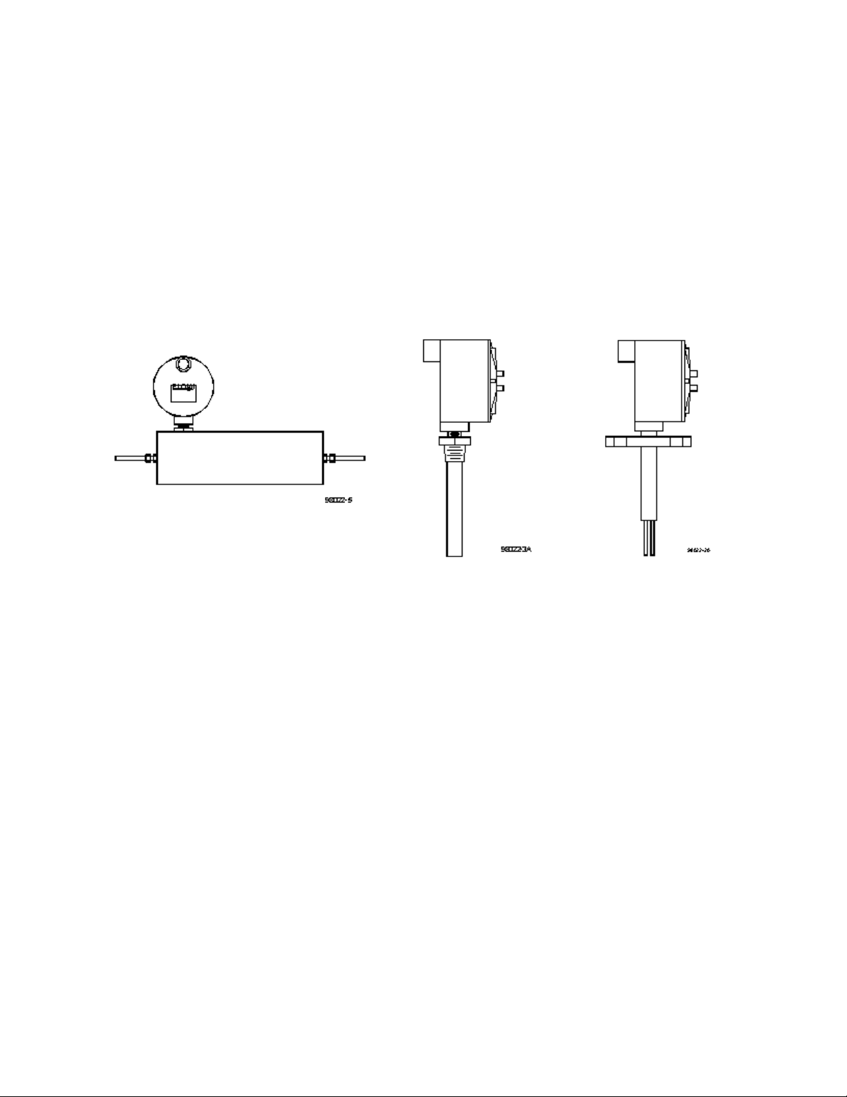
1. TU Transducers
!! CAUTION: TU transducers are made with thin-walled tubing use
care when installing. TU1'16 and TUctransducers require particularly
careful handling.
!! CAUTION: The electronics box should never be rotated for any
reason.
Straight run for a flow switch is not a requirement, particularly for flow/no flow indications,
but for best repeatability some straight run is useful, such as 10 to 20 pipe diameters on the
inlet and 6 to 10 diameters on the outlet. If installed vertically, the flow should be going up
through the sensor. Connection in the line is via compression fittings, hose with clamp,
threaded fittings or flanges, whichever is appropriate. Care must be taken not to transmit a
twisting force through the transducer's midsection. The TU transducer, whether flanged or
not, must not be used to pull other piping together or to make up angular mismatch of fittings.
Typically, TU1'16" O.D. flow tubes are sleeved with a c" tube for added support. Fluid
connections should always be made to the 1'16 " tube, as there is no assured seal between the
1'16" tube and the sleeves.
Fluid temperatures other than ambient require special attention. Thermal gradients from one
end of the transducer to the other, as well as along the radius of the connection pipe, are
undesirable. Therefore, effective insulation should be installed around the inlet and outlet
straight line runs. Gradients which may exist in the line further up stream can be removed if
an insulated elbow is installed in the line prior to entering the straight line portion of the
plumbing.

- 5 -
The ideal installation will provide the sensor with well established smooth flow, uniform
system temperature and consistent fluid media.
2. Intrusive Probes
Straight run is not critical, but if trying to hold a precise set point, some straight run is
useful, such as 10 to 20 pipe diameters on the inlet and at least 6 diameters on the outlet.
The various probe transducers are mounted through a threaded collar (NPT/2I and NPT/I) or
flanged tee (BF/2I or BF/I). Other fittings and sensor designs are also available and are
discussed on the Custom Information page. Generally the probes are sized so the tips extend
½ to 1 inch beyond the pipe center line when properly installed. However, for larger pipes,
the probes may extend in 1/8of a diameter from the wall.
Proper alignment of the sensor with flow is important; the flow direction is indicated on the
transducer tag and/or etched into the transducer. All dual probe transducers (NPT/2I, BF/2I)
are installed so that the two probes are side-by-side across the fluid stream. Never rotate the
electronics box. If this occurs the flow switch could be damaged and/or installed misaligned
with the flow direction.
For high temperature applications, the sensor and surrounding line should be well insulated.
Leave a portion of the transducer neck un-insulated to allow heat dissipation before reaching
the junction box.
2.2 ELECTRICAL CONNECTIONS (See Figure 1 on page 12)
The input power requirement is listed on the tag on the electronics enclosure; make sure the input power
source is compatible. The standard power requirement is 120 Vac, 60 Hz, single phase (220 Vac, 50
Hz and 24 Vdc are options).
Wire sizes no smaller than 24 gauge can be used for power. The electronics power ground is common
to the transducer casing. 14 gauge stranded wire is recommended for the relay contacts (10A resistive
at 120 Vac, 5 Amps resistive at 240 Vac).
The input power and relay connections are made as shown in Figure 1. Note the connector is removable
for easier insertion of the wires. Once all connections are made, firmly push the connector back onto
its base. Be sure the wires are stress relieved sufficiently to prevent an inadvertent disconnect.
The typical housing for a 100CS flow switch is a round explosion-proof enclosure. When ready for use,
the housing lid should be tightly screwed on. A gasket is included when rain tightness is required. Here
again, the lid should be on tight to make a good seal against the gasket.

- 6 -
SECTION 3 !OPERATION
3.1 START UP
Typically, Rheotherm flow switches come from the factory set up for a 10 to 1 flow rate range, and with
the trip level set approximately as requested by the customer. The trip level can be adjusted using the
instructions in SECTION 3.3.
When power is first turned on, the flow switch may indicate a high flow rate, even if there is no flow
occurring. Correct indication of flow level will result after an initial period, which can extend to about
forty (40) seconds and depends on where the trip adjust is set.
For standard flow switches, the relay operates as stated below. For nonstandard units, the operation is
described in SPECIAL INSTRUCTIONS (SECTION 6).
A. Low Flow Switch The relay is energized (N.O. contact is closed) and the LED is green
when the flow rate is above the trip level. Therefore, the alarm condition (relay de-energizes)
occurs when the flow rate drops below the trip level or there is a loss of power to the sensor
(N.O. contact is open and LED color becomes red).
B. High Flow Switch The relay operation is exactly as described above. When used as a high
flow switch, the alarm condition is considered to be when the relay is energized (N.O. contact
is closed and LED color becomes green).
3.2 GENERAL INFORMATION
The Rheotherm instrument is compensated for a wide range of both ambient and flowing media
temperatures. However, abrupt changes in the temperature of the flowing material can cause the
instrument to read the flow rate improperly, which could lead to an inappropriate tripping of the relay
or a delay in reading loss of flow. A proper reading is obtained only when the transducer is in thermal
equilibrium with the material. Typically, a 20°F abrupt change in temperature may require 40 seconds
to stabilize.
In general, the heater used in the transducer does not develop enough power to cause damage to the
system in the absence of flow. This includes those used in liquids even if the line becomes empty and
filled with air. Special cases will be discussed in the section entitled SPECIAL INSTRUCTIONS
(SECTION 6).

- 7 -
3.3 ADJUSTING THE TRIP POINT
Adjust the flow switch trip point as follows (see Figure 2, page 12, for trip potentiometer location):
1. Establish a flow rate at the desired trip level. (This should be done with flow in the line, not
at zero flow. Select a flow rate below your normal usage. One example would be to use 50%
of your lowest normal flow rate as the set point.)
2. If the LED is green, adjust "Trip" potentiometer clockwise until the relay de-energizes (LED
turns red). This is the alarm condition.
3. If LED is red, adjust "Trip" potentiometer slowly counterclockwise just until the relay
energizes (LED turns green).
4. If the relay cannot be made to drop out over the full range of the "Trip" potentiometer, see
TABLE I.
3.4 USE AS A LEVEL SWITCH (Insertion Probes Only)
The probe switch design can be used to provide one point level switch indication. When the probe tips
are submerged in liquid, the relay is energized and the LED is green. When the liquid level drops below
the probes and they are surrounded by air or vapor, the relay de-energizes and the LED turns red.

- 8 -
SECTION 4 !MAINTENANCE
4.1 GENERAL MAINTENANCE
Certain precautions should be taken to insure proper performance of all models of flow instruments.
Since the measurement technique involves a signal resulting from heat transfer to the flowing medium,
care should be exercised to prevent build-up of varying layers on the walls of the transducer. Layers
such as bacterial growth, dried paints, gas bubbles and non-solubles can result in measurement below
actual flow rates. Periodic checks and cleaning should be performed to insure a clean pipe or probe
surface.
It should be part of normal maintenance procedure to check the system for proper functioning.
Experience and other observable conditions should be utilized to determine the frequency of inspection.
To test the flow switch action. the flow rate should be reduced below (for low flow switch) or raised
above (for high flow switch) the switching level. Then check and insure relay action and continuity of
the shut down or warning circuits which it operates.
The joints of all intrusive probes tips should be inspected for wear and corrosion.
4.2 SPARE PARTS
There are no normally recommended spare parts to stock. Should a spare be needed, a complete unit
should be ordered and stocked.
If fuse replacement is ever needed, for AC powered units , use a Wickman part no. 3730500041 (½A,
fast acting fuse) or equivalent. For units powered by 24 Vdc, the fuse is a 1A, slow blow fuse and may
be replaced with Wickman part no. 3741100041 or equivalent.

- 9 -
4.3 TROUBLE SHOOTING
TABLE I. TROUBLE SHOOTING GUIDE
OBSERVATION PROBABLE CAUSE REMEDY
Flow trip level continually drifting
downward with constant flow.
Coating forming on wetted surface
of transducer.
1. Clean transducer periodically.
2. Adjust trip potentiometer
clockwise until layer build-up
stabilizes.
After switch has been operating properly:
Relay trips with flow above trip level and
cannot be adjusted using SECTION 3.3
instructions. Relay does not trip when
flow falls below trip level and cannot be
adjusted using SECTION 3.3 instructions.
Bad electronic component. Contact factory.
Relay cannot be made to trip by adjusting
"Trip" potentiometer.
1. Initial flow rate estimate was
too low or too high.
2. Flow media change.
1. Check flow conditions.
2. Contact factory.
LED is not lit and relay stays in alarm
condition (N.C. contact is made).
1. No power to electronics.
2. Blown fuse.
1. Check incoming power.
2. Replace fuse with ½ Amp fast
acting fuse (fuse is in PCB
socket).
3. Contact factory.
!! CAUTION: The electronics are not protected against condensed liquid water inside the
enclosure. If conduit is used, be sure conduit is dry or sealed at the instrument to prevent conduit
condensation from entering the enclosure.

- 10 -
SECTION 5 !CUSTOMER SERVICE
Intek's corporate philosophy is to solve our customer's difficult flow measurement problems. This
means that each instrument is custom configured and calibrated for the application. When you purchase
a Rheotherm instrument you also receive Intek's outstanding customer service. For sales or product
service, call your local representative or Intek directly at (614) 895-0301, 8AM to 5PM EST/EDT
or [email protected]. Our customer service staff will provide assistance promptly.
5.1 QUESTION ON EXISTING HARDWARE
To allow us to help you more quickly, please have the serial number of the equipment available before
you call.
5.2 TROUBLE SHOOTING
If you have reviewed SECTION 4.4 TROUBLE SHOOTING and have questions, please call our
experienced engineers for assistance. In many cases we can solve a problem over the phone. Please
provide as complete a description as possible of the problems encountered.
5.3 FACTORY AND FIELD SERVICE
If you request field service, Intek has experienced engineers available to meet your needs. Many of the
repairs or recalibrations will require returning the instrument to the factory. If a problem cannot be
solved over the phone, with your help, we will determine if factory service or field service will be the
best solution.
To request factory service, a Return Material Authorization (RMA) and purchase order is required. Our
customer service staff will assist you with the required information to return instruments for service.
5.4 DECONTAMINATION OF EQUIPMENT
For the safety of your personnel and ours, any hardware that has been in contact with potentially
hazardous liquids or gases must be properly decontaminated before shipment to Intek.
5.5 QUESTIONS ON NEW EQUIPMENT
For a new Rheotherm application or any liquid or gas flow measurement need, contact your local
Rheotherm representative or the Intek technical sales department at the above phone/fax numbers. Our
staff will be pleased to answer all questions and provide quotations.

- 11 -
SECTION 6 !CUSTOM INFORMATION
6.1 UNIT IDENTIFICATION
Model no.:
Serial no.:
Customer identification:
6.2 CONFIGURATION
The configuration of this unit, as originally shipped from the factory:
Input Power:
Q115 Vac, 50/60 Hz Q230 Vac, 50/60 Hz Q24 Vdc
Line Connection:
6.3 SPECIAL INSTRUCTIONS
Reference Reference
None Installation
Other
Trip level adjustment required for start up

Figure 1. Model 100CS Interconnect Diagram
Figure 2. Model 100CS PWB Layout Diagram
Other manuals for Rheotherm 100CS
1
Table of contents
Other Intek Switch manuals
Popular Switch manuals by other brands

B&B Electronics
B&B Electronics Elinx EIRP410-2SFP-T quick start guide

Lenze
Lenze 8200 motec Mounting instructions

Lantech
Lantech 5 10/100TX w/ 4 PoE Injector Industrial... user manual

Linkskey
Linkskey LDV-302ARC Quick installation guide

CTC Union
CTC Union ITP-G800SM-8PH24 Quick installation guide

3Com
3Com Baseline Switch 2824 3CBLUG24 user guide