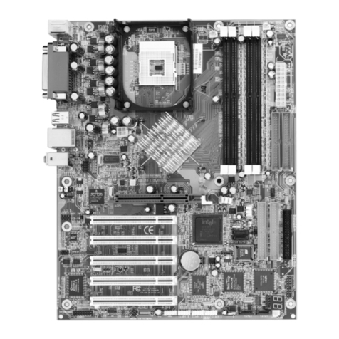
Intel PD440FX User manual

PD440FX
Motherboard
Product
Guide
.
.
_.L.i.
.
.._
.
.._
.i ,.
.
.
.
.
i.
.
.
.
.
.
.
.
.
.
..
.
._..
:....
.::
.
.
.
.
.
.
.
.._.
Order Number:
667613-001

Information in this document is provided in connection with
Intel products. No license, express or implied, by estoppel
or otherwise, to any intellectual property rights is granted
by this document. Except as provided in Intel’s Terms and
Conditions of Sale for such products, Intel assumes no
liability whatsoever, and Intel disclaims any express or
implied warranty, relating to sale and/or use of Intel
products including liability or warranties relating to fitness
for a particular purpose, merchantability, or infringement of
any patent, copyright or other intellectual property right.
Intel products are not intended for use in medical, life
saving, or life sustaining applications.
Intel retains the right to make changes to specifications and
product descriptions at any time, without notice.
The
PD44OFX
motherboard may contain design defects or
errors known as errata. Current characterized errata are
available on request.
t
Third-party brands and trademarks are the property of
their respective owners.
Copyright
0
1997, Intel Corporation.

Contents
1 Product Description
Microprocessor ............................................
7
Main Memory (DRAM)
.................................
7
PCVIDE
Peripheral Interface..
.....................
.9
I/O
Features
...............................................
10
BIOS Features
...........................................
10
PCI
Auto-configuration..
.......................
10
IDE Auto-configuration..
.......................
1 1
ISA Plug and Play Capability
...............
1 1
Security Features
.................................
11
BIOS Upgrades
....................................
11
Expansion Slots
.........................................
11
Real-time Clock and CMOS RAM
..............
1 1
Battery
.......................................................
12
Speaker
.....................................................
12
Fan Connectors
.........................................
12
USB Interface Support
...............................
12
Audio Subsystem
.......................................
13
Hardware Monitor Option
...........................
13
2
Using the BIOS Setup Program
Overview of the BIOS Setup Program . . . . .
..I5
Main Screen
. . . . . . . . . . . . . . . . . . . . . . . . . . . . . . . . . . . . . . . . . . . . . . .
17
Floppy Options
Subscreen . . . . . . . . . . . . . . . . . . . 19
Floppy Access
. . . . . . . . . . . . . . . . . . . . . . . . . . . . . . . . . . . . . .
19
Primary/Secondary IDE Master/Slave
Configuration
Subscreens . . . . . . . . . . . . . . . . 20
Boot Options
Subscreen . . . . . . . . . . . . . . . . . .
.
.
.
.21
Advanced Screen
. . . . . . . . . . . . . . . . . . . . . . . . . . . . . . . . . . . . . . .
25
Peripheral Configuration Subscreen . ...26
Advanced Chipset Configuration
Subscreen
. . . . . . . . . . . . . . . . . . . . . . . . . . . . . . . ...*.....
30
Power Management Configuration
Subscreen
. . . . . . . . . . . . . . . . . . . . . . . . . . . . . . . . . . . . . . . .
31
Plug and Play Configuration
Subscreen
. . . . . . . . . . . . . . . . . . . . ..*...*.............
32
Event Logging Configuration
,
Subscreen
. . . . . . . . . . . . . . . . . . . . . . . . . . . . . . . . . . . . . . . .
35
Security Screen
. . . . . . . . . . . . . . . . . . . . . . . . . . . . . . . . . . . . . . . . . .
38
Exit Screen
. . . . . . . . . . . . . . . . . . ..*............................
40

Contents
3
Installing and Configuring
Motherboard Options
Before You Begin
......................................
41
Jumpers
.....................................................
43
Jumpers for Setup Program Functions..
....
44
How to Disable Access to the
Setup Program
................................
44
How to Enable Access to the
Setup Program
................................ 45
How to Clear CMOS RAM
................... 45
How to Clear the User or Administrator
Password ........................................ 46
How to Install the Processor..
.................... 47
How to Install the Retention
Mechanism ...................................... 47
How to Set the Processor Speed
Jumpers
.......................................... 48
How to Install Memory
............................... 49
How to Remove Memory
........................... 52
How to Replace the Battery..
..................... 52
How to Remove the Motherboard..
............
55
4 Error and Informational Messages
BIOS Beep Codes
..................................... 57
PCI Configuration Error Messages
............
58
BIOS Error Messages
................................ 59
ISA NMI Messages
....................................
61
5 Technical Reference
Motherboard Connectors
........................... 63
CD-ROM Audio Connector
.................. 63
Telephony Connector
.......................... 63
Wavetable Connector
.......................... 64
Telephony Connector
.......................... 64
Audio
Line
In Connector..
.................... 65
Fan 1 Connector
..................................
65
Fan 3 Connector
.................................. 66
Chassis Security Connector..
............... 66
Front Panel Connectors
............................. 67
Motherboard Resources
............................ 68
Memory Map
........................................ 68
I/O
Map
................................................ 69
PCI Configuration Space Map
.............
71
DMA Channels
.....................................
71
Interrupts ............................................. 72

PD44OFX
Motherboard Product Guide
A Information for Computer Integrators
Regulatory Requirements
..........................
73
Safety Standards
.................................
73
Electromagnetic Interference
(EMI)
Regulations
......................................
74
Product Certification
Markings
............
.75
Installation Precautions
..............................
75
Installation Instructions
..............................
76
Ensure Electromagnetic Compatibility
(EMC) ..............................................
76
Ensure Host Computer and Accessory
Module
Certifications
......................
.77
Prevent Power Supply Overload
.........
.78
Place Battery Marking on the
Computer
.........................................
78
Use Only for Intended Applications......7 8
B Upgrade the BIOS
Record the Current BIOS Settings..
..........
.79
How to Upgrade the BIOS
........................
.79
Create a Bootable Floppy Disk
...........
.79
Create the BIOS Upgrade
Floppy Disk
...................................... 80
Make a Copy of the Current BIOS..
..... .81
Upgrade the BIOS
................................
81
How to Recover the BIOS If an
Upgrade Fails
........................................ 82
Figures
1.
Motherboard Components..
...................
.8
2.
Back Panel
I/O
Connectors..
.................
.9
3.
Configuration Jumper Block
................
.43
4. Installing the Processor Retention
Mechanism ........................................... 47
5.
Location of SIMM Sockets
...................
.50
6. Installing a SIMM
..................................
51
7. Replacing the Battery
........................... 54
8.
Mounting Screw Holes
........................
.55
Tables
1.
Overview of the Setup Function Keys . . 16
2.
Overview of the Setup Screens . . . . . . . . . . . .
16
3. Jumpers for Setup Program
Functions
. ..*....................*.....................
44
4.
Jumpers for Processor Speed (MHz) . ..48

Contents
5.
Memory Options for SIMM Sockets..
..
.50
6. Beep Codes
......................................... 57
7.
PCI Configuration Error Messages..
....
58
8. BIOS Error Messages
.......................... 59
9. ISA NMI Messages
..............................
61
10. CD-ROM Audio Connector Pinout..
.....
63
11. Telephony Connector Pinout..
.............
63
12. Wavetable Connector Pinout..
.............
64
13. Telephony Connector Pinout..
.............
64
14. Audio Line In Connector
Pinout..
.........
65
15. Fan
1
Connector
Pinout.. ..................... 65
16. Fan 3 Connector
Pinout.. ..................... 66
17. Chassis Security Connector Pinout..
...
66
18. Front Panel
Connectors..
..................... 67
19. Memory Map
........................................ 68
20.
I/O
Map
................................................ 69
21. PCI Configuration Space Map
.............
71
22. DMA Channels
....................................
71
23. Interrupts
............................................. 72

Product Description
This chapter describes the features of the
PD440FX motherboard. The remaining chapters
explain how to:
l
Use the BIOS Setup program to modify the
motherboard’s configuration
l
Install components like processors or
memory
l
Interpret error messages you might
encounter while running the computer
Figure 1 shows the components on the
motherboard. Figure 2 shows the back panel
connectors on the motherboard.
Microprocessor
The PD440FX motherboard supports 233 MHz
and 266 MHz Intel
Pentium@
II processors with
MMX’” technology and 256 KB or 512 KB
secondary (L2) cache.
The Pentium II processor is packaged in a
Single Edge Contact (S.E.C.) Cartridge that
mounts in the Slot 1 processor connector on the
motherboard.
Main Memory (DRAM)
The motherboard supports up to 256 MB of
DRAM. DRAM is implemented through four
72-pin
SIMMt sockets. The motherboard
contains four SIMM sockets. To add memory to
the motherboard, see Chapter 3. For the
motherboard’s main memory map, see
Chapter 5.
Memory error checking and correction is
supported with parity or ECC SIMMs. Parity or
ECC SIMMs are automatically detected;
however, the user must enter Setup to configure
SIMMs for either parity or ECC operation. Parity
memory will detect single-bit errors. ECC
memory will detect multi-bit errors and correct

1
Product Description
single-bit errors. Errors may be generated by a
defective memory module, mixing different
speed memory modules, or by DMA or memory
A
.
B
.
C
.
conflicts.
D
.
Figure 1. Motherboard Components
E
.
A
BCDEF G
F
.
G
.
H
.
I
.
R
Q
PO N
M
0M05675
K
.
L
.
M
.
N
.
0
.
P
.
Q
.
R
.
S
.
T
.
=
NOTE
Components labeled
%p
tional” do not
come on all
PD44OFX
motherboards.
U
.
v
.
ISA connectors
CD-ROM audio connector
Telephony connector
Wavetable connector
Telephony connector
Audio line in connector
Back panel
I/O
connectors
Slot 1 processor connector
Heatsink support mounting
Power connector
Speaker (optional)
Battery
SIMM sockets
Floppy drive connector
Primary IDE connector
Secondary IDE connector
Front panel connectors
Jumper block
Fan 1 connector
Chassis security connector
Fan 3 connector
PCI connectors
holes

PD44OFX
Motherboard Product Guide
1
Figure 2. Back Panel
I/O
Connectors
A
.
B
.
PS/2t connector (mouse or keyboard
Parallel port connector
I
1
m-c
C
[o-o]
p-&--q
,
t
E
F
G
H
I
J0M05676
C
.
MIDI/game port connector
D
.
PS/2
connector (mouse or keyboard)
E
.
USB connectors
F
.
Serial port 1 connector
G
.
Serial port 2 connector
H
.
Audio line out jack
I
.
Audio line in jack
J
.
Audio mic in jack
PCIADE
Peripheral Interface
The motherboard has a high-speed, 32-bit
PCVIDE
interface that supports the following:
l
Up to four
PCVIDE
hard drives on the PCI
bus
l
PI0
Mode 3 and Mode 4 hard drives
l
Logical block addressing (LBA) of hard
drives larger than 528 MB
l
Extended Cylinder Head Sector (ECHS)
translation modes
l
ATAPI devices (such as CD-ROMs)

1
Product Description
I/O
Features
The I/O controller integrates the functions for the
serial ports, parallel port, diskette drive, and
keyboard. This component provides:
l
Multimode bidirectional parallel port:
-
Standard mode: Centronics-compatible
operation
-
High-speed mode: support for enhanced
capabilities port (ECP) and enhanced
parallel port (EPP)
l Two RS-232C NS16C450/550compatible
g-pin
serial ports
l
Integrated real-time clock with an accuracy of
+13
minutes/year at 25
OC
and 5 V
l Integrated
8042compatible
keyboard
controller
l
Flexible IRQ and DMA mapping to support
Windowst 95
l
Support for an IrDAt or Consumer
IR
compatible infrared interface. The infrared
interface supports data transfer rates of up to
115 K baud with either half- or full-duplex
operation
l
Industry standard diskette drive controller
that supports 720 KB, 1.44 MB, and 2.88 MB
3.5.inch drives (at 135 tracks per inch); and
360 KB and 1.2 MB 5.25-inch drives
BIOS Features
The BIOS, from American Megatrends, Inc.
(AMI),
provides ISA and PCI compatibility. The
BIOS is contained in a Flash memory device
soldered to the motherboard. The BIOS
provides the POST, the Setup program, a PCI
and IDE auto-configuration utility, and BIOS
recovery code.
PCI Auto-configuration
The PCI auto-configuration utility works in
conjunction with the Setup program to support
using PCI add-in cards in the computer. When
you turn on the power after installing a PCI card,
the BIOS automatically configures interrupts,
DMA channels, and
I/O
space. Since PCI add-in
cards use the same interrupt resources as ISA
add-in cards, you must specify the interrupts
used by ISA cards in the Setup program. The

PD44OFX
Motherboard Product Guide
1
PCI auto-configuration program complies with
version 2.1 of the PCI BIOS specification.
IDE Auto-configuration
The motherboard automatically detects installed
IDE devices and configures them for operation.
ISA Plug and Play Capability
The motherboard provides auto-configuration of
Plug and Play ISA cards and resource
management for legacy (non Plug and Play) ISA
cards when used with the ISA Configuration
Utility (ICU) or a Plug and Play compatible
operating system like Windows 95. To obtain
the ICU, contact your computer supplier.
Security Features
The BIOS provides a password option that you
can enable through the Setup program (refer to
Chapter 2).
BIOS Upgrades
Because the BIOS is stored in a Flash memory
device, you can upgrade the BIOS without
having to disassemble the computer. The
upgrade can be done with a utility stored on a
diskette or hard disk or run over a network. To
upgrade the BIOS, see Appendix B.
Expansion Slots
The motherboard has two dedicated
16.bit
ISA/ATt-compatible and three dedicated
PCI-compatible expansion slots. Another
expansion slot is a combination slot that can be
used for either a PCI or an ISA card. This allows
you to install a maximum of six add-in cards.
Real-time Clock and CMOS
RAM
The
I/O
controller provides a real-time clock and
CMOS RAM. You can set the time for the clock
and the CMOS values by using the Setup
program described in Chapter 2.

1
Product Description
Battery Fan Connectors
A battery on the motherboard keeps the clock
and values in CMOS RAM current when your
computer is turned off. To replace the battery,
see Chapter 3.
Speaker
An optional speaker is mounted on the
motherboard. The speaker provides audible
error code information (beep codes) during the
POST if the BIOS cannot use the video
interface. For beep code descriptions, see
Chapter
4.
@S
NOTE
The board also has a connector for an
.
r
To mstall
arr
offboard
speaker,
remove’ the jumper that
enables the onboard speaker (refer to
Chapter
5).
The motherboard has connectors for two fans.
For the locations and
pinouts
of the fan
connectors, see Chapter 5.
USB Interface Support
The USB ports permit the direct connection of
two USB peripherals without an external hub. If
more devices are required, an external hub can
be connected to either of the built-in ports. The
motherboard supports the standard universal
host controller interface (UHCI) and uses
standard software drivers that are UHCI-
compatible.
Features of the USB include:
l
Support for self-identifying, hot-pluggable
peripherals
l Automatic device configuration
l
Support for isochronous and asynchronous
transfers over the same set of wires
l
Support for up to 127 physical devices
l
Bandwidth and low latencies appropriate for
telephony, audio, and other applications
l
Error handling and fault recovery built into
protocol

PD44OFX
Motherboard Product Guide
1
CD NOTE
Computers that have an unshielded cable
attached to the USB port may not meet
FCC Class B requirements, even if no
device or a low-speed USB device is
attached to the cable. Use shielded cable
that meets the requirements for full-speed
devices.
Audio Subsystem
The onboard audio subsystem is based on the
Yamaha OPLt family of single-chip audio
controllers (YM
715).
The audio subsystem
provides the digital audio and analog mixing
functions needed for recording and playing
sound on personal computers. The subsystem
features:
l
Line and microphone level inputs
l MIDI/Game port
l 3-D enhanced stereo
Hardware Monitor Option
The hardware monitor option features the
following:
l
An integrated temperature sensor
l Fanspeedsensors
l
Power supply voltage monitor
l
POST test result and error code storage
l
Support for Intel
LANDesk@
Client Manager
l
Connector for external chassis security
feature
l
Full digital control of all mixer and volume These features are implemented by an
control functions integrated hardware monitor device.
l Full duplex operation
l
Sound Blastert Pro, Windows Sound
System, Roland MPU-401, AdLibt, and
Multimedia PC Level 2 (MPCII) compatibility
l
Onboard Yamaha YM 704 wavetable
synthesizer (optional)
l Wavetable upgrade connector
l CD-ROM audio connector
l Telephony connectors

Using the BIOS Setup Program
This chapter explains how to use the BIOS
Setup program. You can use the Setup program
to change the computer’s configuration
information and boot-up sequence.
Setup information is stored in CMOS random
access memory (RAM) and is backed up by a
battery on the motherboard when power to the
computer is off.
Overview of the BIOS Setup
Program
To enter the Setup program, turn the computer
on and press
cFl>
when you see the message:
“Press
<Fl>
Key if you want to run SETUP.”
You have about five seconds to press
<Fl>
before the boot process continues.
=
NOTE
For reference purposes, you should write
down the current Setup settings. When
you make changes to the settings, update
this record.
When you enter the Setup program, you will see
the Main screen. Listed along the top of the
display are three other screens: Advanced,
Security, and Exit.
Select a screen by pressing the left
et->
or right
C-D
arrow keys. Use the up
&
or down
&
arrow keys to select items within a screen. Use
the <Enter> key to select an item you want to
change. For some items, pressing
<Enter>
brings up a subscreen. After you have selected
an item, use the arrow keys to change the
setting.

2
Using the BIOS Setup Program
Table 1 provides an overview of function keys in
the Setup program. Table 2 provides an
overview of the menu screens and subscreens
Table 2. Overview of the Setup Screens
Setup Screen
..................................
. . . . . . . . . . .
.
.
.
.
..
.
.
.
.
.
.
.
.
.
.
.
.
.
.
.
.
.
.
.
.
.
.
.
.
.
.
. .
.
.
.
.
.
.
.
.
i...
This Screen is Used To
in the Setup program.
Main
Configure basic features
such as time, date, floppy
drives, and hard drives
Table 1.
OVerVieW
Of the Setup Function Keys
“‘Advanced
Configure advanced features
such as peripheral
configuration, audio
configuration, and advanced
chipset configuration
Setup Key
Description
Brings up a help screen for the current item
<Fl>
<Esc>
Backs up to the previous screen
In the Main, Advanced, Security, or Exit
screen allows you to exit while discarding
changes (see page 40)
Security Set passwords
..j..
‘.
1.
_:__
Exit
.. .
.
Floppy Options
Save or discard changes
.
.
.
.
.
.
.
.
Configure a floppy drive
<Enter>
Selects the current item or option
,.,
.,
_..
..,_
.
..A
“..
I
.
I
.
.
x
.
I
,,,
,,.
r
.
.
.
,.
.
.
.
.
.
..,
.
.
.
,
Selects the previous item or option --
^-.
--
Selects’the next item ‘or option
Primary/Secondary IDE
Master/Slave Configuration
Boot Options
Configure IDE devices
CT>
Configure how the computer
boots up
‘Configure the serial ports,
the parallel port, and the
hard disk drive interfaces
Configure the memory and
data buses
. .
continued
(*
<+>
c+>
In the Main, Advanced, Security, or Exit
menu screens, changes the menu screen Peripheral Configuration
<F5>
Loads Setup defaults (see page 40)
,,
,.
,
,,,,,_
,
,_
._,.
,
,_,
r.
.,
,,,
.r..
,
__,_
,__,
Discards current
chang&see
page 40)
A
.,,.
,
Exits while saving changes (see page
40)
<F6>
Advanced Chipset
Configuration
<Fl
O>

PD44OFX
Motherboard Product Guide
2
Table 2. Overview of the Setup Screens
(continued)
Setup Subscreen
.,...,,,,...,....
.
.
.
.
.
.
.
.
.
.
.
.
.
.
.
.
..t
Power Management
Configuration
.._
.__ _.
.
.
.
.
.
.
.
.
.
.
.
.
.
.
.
.
.
.
.
.
.
.
. .
.
.
.
Plug and Play
Configuration
_. .
.
.
.
Event Logging
Configuration
,..
..t......
Single Bit ECC Events
.
Multiple Bit ECC Events
.
Parity Error Events
Pre-Boot Events
This Subscreen is Used To
Configure the computer’s
power management options
Configure the computer’s
Plug and Play capabilities
Configure the computer’s
event logging functions
.
Report about logged events
Main Screen
This section describes the options in the Main
screen. If you select some options from the
main screen (for example, Primary IDE Master),
the Setup program displays a subscreen for the
selected option.
System Date
Specifies the current date. Select the month
from a pop-up menu and type the date and year.
Report about logged events
___.__
____......,,,...,.............,,,..........,.....,........,..................
.
.
.
.
.
.
.
.
.
.
.
.
.
.
.
.
.
.
.
.
.
.
Report about logged events System Time
Specifies the current time.
Report about logged events Floppy Options
When selected, this displays the Floppy Options
subscreen.
Primary IDE Master
Reports if an IDE device is connected to the
Primary IDE Master interface. When selected,
this brings up the Primary IDE Master
Configuration subscreen.

2
Using
the BIOS Setup Program
Primary IDE Slave Video Mode
Reports if an IDE device is connected to the
Primary IDE Slave interface. When selected,
this brings up the Primary IDE Slave
Configuration subscreen.
Reports the video mode. There are no options.
Mouse
Secondary IDE Master
Reports if an IDE device is connected to the
Secondary IDE Master interface. When
selected, this brings up the Secondary IDE
Master Configuration subscreen.
Reports if a
PS/2
mouse is installed. There are
no options.
Base Memory
Reports the amount of base memory. There are
no options.
Secondary IDE Slave
Reports if an IDE device is connected to the
Secondary IDE Slave interface. When selected,
this brings up the Secondary IDE Slave
Configuration subscreen.
Extended Memory
Reports the amount of extended memory. There
are no options.
Language
BIOS Version
Reports the BIOS version. There are no
options.
Specifies the language of the text strings used in
the Setup program and the BIOS. The options
are any installed languages.
Boot Options
When selected, this brings up the Boot Options
subscreen.

PD44OFX
Motherboard Product Guide
2
Floppy Options Subscreen
Floppy A:
Reports if a floppy drive is connected to the
system. There are no options.
Floppy B:
Reports if a second floppy drive is connected to
the system. There are no options.
Floppy A: Type
Specifies the physical size and capacity of the
floppy drive. The options are:
l Disabled
l 360 KB, 5.25inch
l 1.2 MB, 5.25inch
l 720 KB,
3.5-inch
l
1.44/1.25
MB,
35inch
(default)
l 2.88 MB,
3.5-inch
Floppy B: Type
Specifies the physical size and capacity of the
floppy drive. The options are:
l Disabled (default)
l 360 KB, 5.25.inch
l 1.2 MB, 5.25.inch
l 720 KB, 3.5-inch
l
1.44/l
.25
MB, 3.5,inch
l 2.88 MB, 3.5.inch
Floppy Access
The BIOS displays this item only if the
motherboard supports changing the read/write or
read-only access for floppy drives. The following
options change the access for all attached
floppy drives:
l Read/Write (default)
l Read Only

2
Using the BIOS Setup Program
Primary/Secondary IDE
Master/Slave Configuration
Subscreens
There are four subscreens used to enable
IDE devices (e.g., hard disks):
l Primary IDE Master
l Primary IDE Slave
l Secondary IDE Master
l Secondary IDE Slave
Each of these subscreens contains the following
eight fields.
IDE Device Configuration
Used to manually configure or autoconfigure the
attached IDE device. The options are:
l Auto Configured (default)
l User Definable
l Disabled
Heads, Sectors items can be
select Disabled, the BIOS wil
drive on that interface.
If you select User Definable, the Cylinders,
specified. If you
I not scan
for a
Cylinders
If IDE Device Configuration is set to User
Definable, type the correct number of cylinders
for the installed hard disk. If IDE Device
Configuration is set to Auto Configured, this
field reports the number of cylinders for the hard
disk.
Heads
If IDE Device Configuration is set to User
Definable, type the correct number of heads for
the installed hard disk. If IDE Device
Configuration is set to Auto Configured, this field
reports the number of heads for the hard disk.
Sectors
If IDE Device Configuration is set to User
Definable, type the correct number of sectors for
the installed hard disk. If IDE Device
Configuration is set to Auto Configured, this field
reports the number of sectors for the hard disk.
Maximum Capacity
Reports the maximum capacity of the hard disk.
Capacity is calculated from the number of
cylinders, heads, and sectors. There are
no options.

PD44OFX
Motherboard Product Guide
2
IDE Translation Mode
A
1
0
CAUTION
Do not change the IDE translation mode
after the IDE device has been formatted.
Changing the option could corrupt data.
Specifies the IDE translation mode. The
.
Check the specifications for the hard disk to
determine which setting provides optimum
performance.
l
Standard CHS (standard cylinder head
sector: fewer than 1024 cylinders)
l Logical Block
l
Extended CHS (extended cylinder head
sector: more than 1024 cylinders)
Fast Programmed
I/O
Modes
Sets how fast transfers on the IDE interface
occur. The options are:
l Disabled
l Auto Detected (default)
If this option is set to Disabled, transfers occur at
a less than optimized speed. If it is set to Auto
Detected, transfers occur at maximum speed.
l
Auto Detected (default) (BIOS detects IDE
translation mode)
Boot Options Subscreen
This section describes the options in the Boot
Options subscreen.
Multiple Sector Setting First Boot Device
Sets the number of sectors transferred by an Sets which drive the computer checks first to find
IDE drive per interrupt generated. The options an operating system to boot from. The options
are:
are:
l Disabled l Disabled
l 4 Sectors/Block
l 8 Sectors/Block
l Auto Detected (default)
l Floppy (default)
l Hard Disk
. CD-ROM
l Network
Other manuals for PD440FX
1
Table of contents
Other Intel Motherboard manuals

Intel
Intel BLKDH67CL Configuration guide

Intel
Intel MS-6112 User manual

Intel
Intel BLKDX58OG Configuration guide

Intel
Intel DG965SS User manual

Intel
Intel D848PMB User manual

Intel
Intel BX80623I52500 User manual

Intel
Intel H61 Express User manual

Intel
Intel DK440LX User manual

Intel
Intel DG41WV User manual

Intel
Intel S1200BT User manual

Intel
Intel DG33FBC User manual

Intel
Intel H310 User manual

Intel
Intel BLKDH61WWB3 User manual

Intel
Intel Desktop Board D845GVFN User manual

Intel
Intel DG41TY User manual

Intel
Intel D865PCD User manual

Intel
Intel MS440GX User manual

Intel
Intel BLKD955XCSLKR Configuration guide

Intel
Intel D865GSA User manual

Intel
Intel BOXDH67CL User manual