Intel S5000XVNSATA User manual

Intel®Workstation Board S5000XVN
Technical Product Specification
Intel order number: D66403-006
Revision 1.5
August 2010
Enterprise Platforms and Services Division – Marketing

Intel® Workstation Board S5000XVN TPS Revision History
Revision 1.5
Intel order number: D66403-006
ii
Revision History
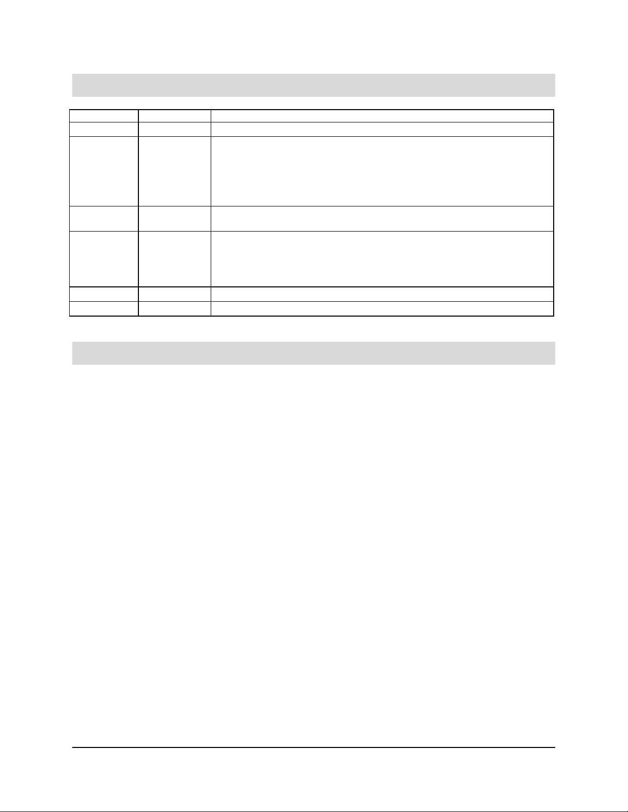
Date Revision Number Modifications
August 2006 1.0 First production S5000XVN Technical Product Specification.
March 2007 1.1 Updated Table 1, Figure 1, and Section 3.1.2.
Added Section 3.6.6.
Updated Section 6.1 and 6.2.
Updated Table 33, Appendix A and Table 44.
Added Section 8.2.
June 2007 1.2 Updated to reflect new processor support and new product codes whereever
applicable.
April 2009 1.3 Updated Section 6.3 BIOS Select Jumper.
Updated the Front Panel SSI Standard 24-pin Connector Pin-out (J1E4) table.
Updated Table 1 and Table 8.
Removed ‘dual-core’ from the processor definition.
April 2010 1.4 Removed section 9.3.7 CNCA (CCC-China).
August 2010 1.5 Added Table 6 for quad rank memory and corrected the title of Table 16.
Disclaimers
Information in this document is provided in connection with Intel®products. No license, express or implied, by
estoppel or otherwise, to any intellectual property rights is granted by this document. Except as provided in Intel's
Terms and Conditions of Sale for such products, Intel assumes no liability whatsoever, and Intel disclaims any
express or implied warranty, relating to sale and/or use of Intel products including liability or warranties relating to
fitness for a particular purpose, merchantability, or infringement of any patent, copyright or other intellectual property
right. Intel products are not intended for use in medical, life saving, or life sustaining applications. Intel may make
changes to specifications and product descriptions at any time, without notice.
Designers must not rely on the absence or characteristics of any features or instructions marked "reserved" or
"undefined." Intel reserves these for future definition and shall have no responsibility whatsoever for conflicts or
incompatibilities arising from future changes to them.
The Intel®Workstation Board S5000XVN may contain design defects or errors known as errata which may cause the
product to deviate from published specifications. Current characterized errata are available on request.
Intel Corporation server baseboards contain a number of high-density VLSI and power delivery components that need
adequate airflow to cool. Intel’s own chassis are designed and tested to meet the intended thermal requirements of
these components when the fully integrated system is used together. It is the responsibility of the system integrator
that chooses not to use Intel developed server building blocks to consult vendor datasheets and operating parameters
to determine the amount of air flow required for their specific application and environmental conditions. Intel
Corporation cannot be held responsible if components fail or the server board does not operate correctly when used
outside any of their published operating or non-operating limits.
Intel, Pentium, Itanium, and Xeon are trademarks or registered trademarks of Intel Corporation.
*Other brands and names may be claimed as the property of others.
Copyright © Intel Corporation 2010.

Intel® Workstation Board S5000XVN TPS Table of Contents
Revision 1.5
Intel order number: D66403-006
iii
Table of Contents
1. Introduction ..........................................................................................................................1
1.1 Chapter Outline........................................................................................................ 1
1.2 Server Board Use Disclaimer .................................................................................. 1
2. Overview ...............................................................................................................................2
2.1 Workstation Board Feature Set ...............................................................................2
2.2 Workstation Board Layout .......................................................................................3
2.2.1 Workstation Board Connector and Component Layout ........................................... 4
2.2.2 Workstation Board Mechanical Drawings ................................................................ 6
2.2.3 Workstation Board ATX I/O Layout........................................................................ 12
3. Functional Architecture.....................................................................................................13
3.1 Intel®5000X Memory Controller Hub (MCH) ......................................................... 14
3.1.1 System Bus Interface............................................................................................. 14
3.1.2 Processor Support ................................................................................................. 14
3.1.3 Memory Subsystem ............................................................................................... 16
3.1.4 Snoop Filter ........................................................................................................... 24
3.2 Enterprise South Bridge (ESB2-E) ........................................................................ 24
3.2.1 PCI Subsystem ...................................................................................................... 24
3.2.2 Serial ATA Support ................................................................................................ 26
3.2.3 Parallel ATA (PATA) Support ................................................................................ 27
3.2.4 USB 2.0 Support.................................................................................................... 27
3.3 Audio Codec .......................................................................................................... 28
3.4 SAS Controller ....................................................................................................... 29
3.4.1 SAS RAID Support ................................................................................................ 29
3.4.2 SAS/SATA Connector Sharing .............................................................................. 29
3.5 Network Interface Controller (NIC) ........................................................................ 29
3.5.1 Intel®I/O Acceleration Technolgy (Intel®I/OAT).................................................... 30
3.5.2 MAC Address Definition......................................................................................... 30
3.6 Super I/O ............................................................................................................... 31
3.6.1 Serial Ports ............................................................................................................ 31
3.6.2 Floppy Disk Controller ........................................................................................... 31
3.6.3 Keyboard and Mouse Support ............................................................................... 31
3.6.4 Wake-up Control.................................................................................................... 31
3.6.5 System Health Support.......................................................................................... 32
3.6.6 Trusted Platform Module (TPM) ............................................................................ 32
4. Platform Management........................................................................................................33

Table of Contents Intel® Workstation Board S5000XVN TPS
Revision 1.5
Intel order number: D66403-006
iv
5. Connector/Header Locations and Pin-outs......................................................................35
5.1 Board Connector Information................................................................................. 35
5.2 Power Connectors ................................................................................................. 36
5.3 System Management Headers .............................................................................. 37
5.3.1 LCP/AUX IPMB Header ......................................................................................... 37
5.3.2 IPMB Header ......................................................................................................... 38
5.3.3 HSBP Header ........................................................................................................ 38
5.3.4 SGPIO Header....................................................................................................... 38
5.3.5 SES I2C.................................................................................................................. 38
5.3.6 HDD Activity LED Header...................................................................................... 38
5.4 Front Panel Connector........................................................................................... 39
5.5 I/O Connectors....................................................................................................... 39
5.5.1 NIC Connectors ..................................................................................................... 39
5.5.2 IDE Connector ....................................................................................................... 40
5.5.3 SATA/SAS Connectors.......................................................................................... 41
5.5.4 Serial Port Connectors........................................................................................... 41
5.5.5 Keyboard and Mouse Connector ........................................................................... 42
5.5.6 USB Connector...................................................................................................... 42
5.5.7 CD-IN Header ........................................................................................................ 43
5.5.8 Audio Connectors .................................................................................................. 43
5.6 Fan Headers .......................................................................................................... 44
6. Jumper Blocks....................................................................................................................46
6.1 CMOS Clear and Password Reset Usage Procedure ........................................... 47
6.2 BMC Force Update Procedure .............................................................................. 47
6.3 BIOS Select Jumper .............................................................................................. 48
7. Intel®Light Guided Diagnostics........................................................................................49
7.1 5 Volt Standby LED ...............................................................................................49
7.2 Fan Fault LEDs...................................................................................................... 50
7.3 System ID LED and System Status LED ............................................................... 51
7.3.1 System Status LED – BMC Initialization................................................................ 53
7.4 DIMM Fault LEDs .................................................................................................. 53
7.5 Processor Fault LEDs............................................................................................ 54
7.6 Post Code Diagnostic LEDs ..................................................................................54
8. Design and Environmental Specifications.......................................................................56
8.1 Intel®Workstation Board S5000XVN Design Specifications.................................. 56
8.2 Board-level MTBF.................................................................................................. 57

Intel® Workstation Board S5000XVN TPS Table of Contents
Revision 1.5
Intel order number: D66403-006
v
8.3 Workstation Board Power Requirements............................................................... 57
8.3.1 Processor Power Support...................................................................................... 59
8.4 Power Supply Output Requirements ..................................................................... 59
8.4.1 Grounding .............................................................................................................. 60
8.4.2 Standby Outputs .................................................................................................... 60
8.4.3 Remote Sense ....................................................................................................... 60
8.4.4 Voltage Regulation ................................................................................................ 60
8.4.5 Dynamic Loading ................................................................................................... 61
8.4.6 Capacitive Loading ................................................................................................ 61
8.4.7 Ripple/Noise .......................................................................................................... 62
8.4.8 Timing Requirements............................................................................................. 63
8.4.9 Residual Voltage Immunity in Standby Mode ........................................................ 65
9. Regulatory and Certification Information.........................................................................66
9.1 Product Regulatory Compliance ............................................................................ 66
9.1.1 Product Safety Compliance ................................................................................... 66
9.1.2 Product EMC Compliance – Class A Compliance ................................................. 66
9.1.3 Certifications/Registrations/Declarations ............................................................... 67
9.2 Product Regulatory Compliance Markings ............................................................ 67
9.3 Electromagnetic Compatibility Notices ..................................................................68
9.3.1 FCC Verification Statement (USA) ........................................................................ 68
9.3.2 ICES-003 (Canada) ............................................................................................... 68
9.3.3 Europe (CE Declaration of Conformity) ................................................................. 69
9.3.4 VCCI (Japan) ......................................................................................................... 69
9.3.5 BSMI (Taiwan) ....................................................................................................... 69
9.3.6 RRL (Korea)........................................................................................................... 69
9.4 Restriction of Hazardous Substances (RoHS) Compliance................................... 70
Appendix A: Integration and Usage Tips................................................................................71
Appendix B: BMC Sensor Tables............................................................................................72
Appendix C: POST Code Diagnostic LED Decoder...............................................................87
Appendix D: POST Code Errors ..............................................................................................91
Appendix E: Supported Intel®Server Chassis.......................................................................94
Glossary.....................................................................................................................................95
Reference Documents..............................................................................................................98

List of Figures Intel® Workstation Board S5000XVN TPS
Revision 1.5
Intel order number: D66403-006
vi
List of Figures
Figure 1. Workstation Board Photograph...................................................................................... 3
Figure 2. Major Board Components.............................................................................................. 5
Figure 3. Mounting Hole Positions ................................................................................................ 6
Figure 4. Component Positions.....................................................................................................7
Figure 5. Restricted Areas on Side 1 ............................................................................................8
Figure 6. Restricted Areas on Side 2 ............................................................................................9
Figure 7. Restricted Areas on Side 2, “Detail B” ......................................................................... 10
Figure 8. CPU and Memory Duct Keepout ................................................................................. 11
Figure 9. ATX I/O Layout ............................................................................................................ 12
Figure 10. Functional Block Diagram.......................................................................................... 13
Figure 11. CEK Processor Mounting ..........................................................................................16
Figure 12. Memory Layout .......................................................................................................... 17
Figure 13. Minimum 2-DIMM Memory Configuration .................................................................. 21
Figure 14. Recommended Four DIMM Configuration ................................................................. 22
Figure 15. Single Branch Mode Sparing DIMM Configuration .................................................... 23
Figure 16. Audio Subsystem Block Diagram ..............................................................................28
Figure 17. Rear I/O Panel Audio Connector ............................................................................... 29
Figure 18. SMBUS Block Diagram.............................................................................................. 34
Figure 19. Jumper Blocks (J1C3, J1D1, J1D2, and J1E32) ....................................................... 46
Figure 20. 5 Volt Standby Status LED Location.......................................................................... 49
Figure 21. Fan Fault LED Locations ........................................................................................... 50
Figure 22. System ID LED and System Status LED Locations................................................... 51
Figure 23. DIMM Fault LED Locations........................................................................................ 53
Figure 24. Processor Fault LED Locations ................................................................................. 54
Figure 25. POST Code Diagnostic LED Location ....................................................................... 55
Figure 26. Power Distribution Block Diagram ............................................................................. 58
Figure 27. Output Voltage Timing ...............................................................................................64
Figure 28. Turn On/Off Timing (Power Supply Signals).............................................................. 65
Figure 29. Diagnostic LED Placement Diagram .........................................................................87

Intel® Workstation Board S5000XVN TPS List of Tables
Revision 1.5
Intel order number: D66403-006
vii
List of Tables
Table 1. Workstation Board Features ........................................................................................... 2
Table 2. Processor Support Matrix ............................................................................................. 14
Table 3. I2C Addresses for Memory Module SMB ...................................................................... 17
Table 4. Maximum Eight-DIMM System Memory Configruation – x8 Single Rank ..................... 18
Table 5. Maximum Eight-DIMM System Memory Configuration – x4 Dual Rank........................ 18
Table 6. Maximum Eight-DIMM System Memory Configuration – x2 Quad Rank ...................... 18
Table 7. DIMM Population Rules ................................................................................................ 20
Table 8. PCI Bus Segment Characteristics................................................................................. 25
Table 9. NIC2 Status LED........................................................................................................... 30
Table 10. Serial B Header Pin-out ..............................................................................................31
Table 11. Board Connector Matrix .............................................................................................. 35
Table 12. Power Connector Pin-out (J9B5) ................................................................................ 36
Table 13. 12-V Power Connector Pin-out (J3J2) ........................................................................ 37
Table 14. Power Supply Signal Connector Pin-out (J9D1) ......................................................... 37
Table 15. P12V4 Power Connector Pin-out (J5A2) ....................................................................37
Table 16. LCP/AUX IPMB Header Pin-out (J2J1)....................................................................... 37
Table 17. IPMB Header Pin-out (J4J1) ....................................................................................... 38
Table 18. HSBP Header Pin-out (J1J7, J1J2) ............................................................................ 38
Table 19. SGPIO Header Pin-out (J2H1, J1J5) .......................................................................... 38
Table 20. SES I2C Header Pin-out (J1J3)................................................................................... 38
Table 21. HDD Activity LED Header Pin-out (J2J3).................................................................... 38
Table 22. Front Panel SSI Standard 24-pin Connector Pin-out (J1E4) ......................................39
Table 23. RJ-45 10/100/1000 NIC Connector Pin-out (JA6A1, JA6A2)...................................... 39
Table 24. IDE 40-pin Connector Pin-out (J2J2) .......................................................................... 40
Table 25. SATA/SAS Connector Pin-out (J1J1, J1H2, J1H1, J1G2, J1G1, J1F2) ..................... 41
Table 26. External DB9 Serial A Port Pin-out (J7A1).................................................................. 41
Table 27. Internal 9-pin Serial B Header Pin-out (J1B1)............................................................. 42
Table 28. Stacked PS/2 Keyboard and Mouse Port Pin-out (J9A1) ........................................... 42
Table 29. External USB Connector Pin-out (JA6A1, JA6A2)...................................................... 43
Table 30. Internal USB Connector Pin-out (J3J1)....................................................................... 43
Table 31. CD-IN Header Pin-out (J4A1) ..................................................................................... 43
Table 32. SSI 4-pin Fan Header Pin-out (J9J1, J5J1, J9B3, and J9B4)..................................... 44

List of Tables Intel® Workstation Board S5000XVN TPS
Revision 1.5
Intel order number: D66403-006
viii
Table 33. SSI 6-pin Fan Header Pin-out (J3H1, J3H2, J3H3, and J3H4)................................... 44
Table 34. Server Board Jumpers (J1C3, J1D1, J1D2, and J1E3) .............................................. 46
Table 35. System Status LED.....................................................................................................52
Table 36. Workstation Board Design Specifications ................................................................... 56
Table 37. Intel®Xeon®Processor Dual Processor TDP Guidelines ...........................................59
Table 38. 550 W Load Ratings ...................................................................................................59
Table 39. Voltage Regulation Limits ........................................................................................... 61
Table 40. Transient Load Requirements..................................................................................... 61
Table 41. Capacitive Loading Conditions ................................................................................... 62
Table 42. Ripple and Noise......................................................................................................... 63
Table 43. Output Voltage Timing ................................................................................................63
Table 44. Turn On/Off Timing ..................................................................................................... 64
Table 45. BMC Sensors.............................................................................................................. 74
Table 46. POST Progress Code LED Example .......................................................................... 87
Table 47. Diagnostic LED POST Code Decoder ........................................................................ 88
Table 48. POST Error Messages and Handling.......................................................................... 91
Table 49. POST Error Beep Codes ............................................................................................93
Table 50. BMC Beep Codes .......................................................................................................93

Intel® Workstation Board S5000XVN TPS List of Tables
Revision 1.5
Intel order number: D66403-006
ix
<This page is intentionally left blank.>

Intel® Workstation Board S5000XVN TPS Introduction
Revision 1.5
Intel order number: D66403-006
1
1. Introduction
This Technical Product Specification (TPS) provides board-specific information about the
features, functionality, and high-level architecture of the Intel®Workstation Board S5000XVN.
See the Intel®S5000 Server Board Family Datasheet for details about board subsystems,
including the chipset, BIOS, and server management.
In addition, design level information for specific subsystems can be obtained by ordering the
External Product Specifications (EPS) for a given subsystem. EPS documents are not publicly
available and must be ordered through your local Intel representative.
The Intel®Workstation Board S5000XVN may contain design defects or errors known as errata
which may cause the product to deviate from published specifications. Refer to the Intel®Server
Board S5000XVN Specification Update for published errata.
1.1 Chapter Outline
This document is divided into the following chapters
Chapter 1 – Introduction
Chapter 2 – Workstation Board Overview
Chapter 3 – Functional Architecture
Chapter 4 – Platform Management
Chapter 5 – Connector and Header Location and Pin-out
Chapter 6 – Configuration Jumpers
Chapter 7 – Light-Guided Diagnostics
Chapter 8 – Power and Environmental specifications
Chapter 9 – Regulatory and Certification Information
Appendix A – Integration and Usage Tips
Appendix B – BMC Sensor Tables
Appendix C – POST Code Diagnostic LED Decoder
Appendix D – POST Code Errors
Appendix E – Supported Intel®Server Chassis
Glossary
Reference Documents
1.2 Server Board Use Disclaimer
Intel Corporation server boards support add-in peripherals and contain a number of high-density
VLSI and power delivery components that need adequate airflow to cool. Intel ensures through
its own chassis development and testing that when Intel server building blocks are used
together, the fully integrated system will meet the intended thermal requirements of these
components. It is the responsibility of the system integrator who chooses not to use Intel-
developed server building blocks to consult vendor datasheets and operating parameters to
determine the amount of air flow required for their specific application and environmental
conditions. Intel Corporation cannot be held responsible if components fail or the server board
does not operate correctly when used outside any of their published operating or non-operating
limits.

Overview Intel® Workstation Board S5000XVN TPS
Revision 1.5
Intel order number: D66403-006
2
2. Overview
The Intel®Workstation Board S5000XVN is a monolithic printed circuit board (PCB) with
features that support the pedestal workstation market.
2.1 Workstation Board Feature Set
Table 1. Workstation Board Features
Feature Description
Processors Socket J (771-pin LGA sockets) supporting one or two Intel®Xeon®processors 5000
sequence, with system bus speeds of 667 MHz, 1066 MHz, and 1333 MHz.
Memory Eight DIMM sockets supporting fully buffered DIMM technology (FBDIMM) memory.
240-pin DDR2-533 and DDR2-677 FBDIMMs can be used.
Chipset Intel®5000X Memory Controller Hub
Intel®ESB2-E I/O Controller
Onboard
Connectors/Headers
External connections:
Stacked PS/2* ports for keyboard and mouse
DB9 serial port A connector
Two RJ-45/2xUSB connectors for 10/100/1000 Mb and USB 2.0 support
One USB 2x5 pin header, which supports two USB ports
One USB port Type A connector
One DH10 serial port B header
Six SATA-2 connectors with integrated RAID 0, 1, and 10 support
(order codes S5000XVNSATAR & BB5000XVNSATAR only)
Software RAID 5 support through an optional SATA RAID KEY
Two SATA-2 connectors and four SATA-2/SAS connectors with integrated RAID 0,
1, and 10 support (order codes S5000XVNSASR & BB5000XVNSASR only)
Software RAID 5 support through an optional SAS RAID KEY (order codes
S5000XVNSASR and BB5000XVNSASR only)
Stacked audio connectors (audio in, audio out, microphone)
One ATA100 40-pin connector
SSI-compliant front panel header
SSI-compliant 24-pin main power connector, supporting the ATX-12 V standard on
the first 20 pins
Add-in PCI, PCI-X*, and
PCI Express* Cards
One full-length/full-height PCI-X 64-bit slot with up to 100 MHz support
One full-length/full-height PCI-X 64-bit slot with up to 133-MHz support when only
one PCI-X slot is populated
One full-length/full-height PCI Express* x4 (x4 throughput) - (x8 (x8 throughput)
with order codes S5000XVNSATAR & BB5000XVNSATAR only) slot
One half-length/full-height PCI Express* x4 (x4 Throughput) slot
One full-length/full-height PCI Express* x16 (x16 throughput) slot
Audio Realtec* ALC260 2-channel high-definition audio codec with universal audio
architecture (24-bit, 2-channel DAC, two stereo 20-bit ADCs)
Hard Drive Support for six SATA-2 hard drives
Support for four SAS hard drives (order codes S5000XVNSASR and BB5000XVNSASR
only)
LAN Two 10/100/1000 Intel®82563EB PHYs supporting Intel®I/O Acceleration Technology

Intel® Workstation Board S5000XVN TPS Overview
Revision 1.5
Intel order number: D66403-006
3
Feature Description
Fans Support for
Two processor fans
Four front hot-swap fans
Two rear system fans
Server Management Support for Intel®System Management Software
2.2 Workstation Board Layout
Figure 1. Workstation Board Photograph

Overview Intel® Workstation Board S5000XVN TPS
Revision 1.5
Intel order number: D66403-006
4
2.2.1 Workstation Board Connector and Component Layout
The following figure shows the board layout of the workstation board. Each connector and major
component is identified by a letter. A component descriptions table follows the figure.
AF000499
O
KL
M
N
S
P
Q
R
LL
NN
OO PP
QQ
RR
KK
JJ
II
HH
GG
FF EE
A B E
DC I
V
AACC
DD ZBB
Y
X
WU
T
FJ
H
MM
G
A. PCI-X* 64-bit, 100-MHz full-
length/full-height slot 1
P. Processor 1 socket EE. Enclosure management SAS
SES I2C (order code
S5000XVNSASR only)
B. PCI-X 64-bit, 133-/100-MHz full-
length/full-height slot 2
Q. Processor 2 socket FF. Hot-swap backplane A header
C. PCI Express* x4
(S5000XVNSASR) or x8
(S5000XVNSATAR) full-length/full-
height slot 3 (x8 connector)
R. Processor 2 fan header GG. SATA 0
D. PCI Express* x4 half-length/full-
height slot 4 (x8 connector)
S. Processor 1 fan header HH. SATA 1
E. CMOS battery T. System fan 4 header II. SATA 2 or SAS 0 (SAS 0 on order
code S5000XVNSASR only)
F. PCI Express x16 full-length/full-
height slot 6 (x16 connector)
U. System fan 3 header JJ. SATA 3 or SAS 1 (SAS 1 on
order code S5000XVNSASR only)
G. CD-ROM line-in connector V. IPMB connector KK. SATA 4 or SAS 2 (SAS 2 on
order code S5000XVNSASR only)

Intel® Workstation Board S5000XVN TPS Overview
Revision 1.5
Intel order number: D66403-006
5
H. P12V4 connector W. System fan 2 header LL. SATA 5 or SAS 3 (SAS 3 on
order code S5000XVNSASR only)
I. Back panel I/O ports X. System fan 1 header MM. USB port
J. Diagnostic and Identify LEDs Y. Processor power connector NN. Front control panel header
K. System fan 6 header Z. USB header OO. SATA software RAID 5 key
connector
L. System fan 5 header AA. IDE connector PP. SAS software RAID 5 key
connector (order code
S5000XVNSASR only)
M. Main power connector BB. Enclosure management SATA
SGPIO header
QQ. Serial B/emergency
management port header
N. Auxilliary power signal connector CC. Hot-swap backplane B header RR. Chassis intrusion header
O. DIMM sockets DD. Enclosure management SAS
SGPIO header (order code
S5000XVNSASR only)
Figure 2. Major Board Components

Overview Intel® Workstation Board S5000XVN TPS
Revision 1.5
Intel order number: D66403-006
6
2.2.2 Workstation Board Mechanical Drawings
Figure 3. Mounting Hole Positions

Intel® Workstation Board S5000XVN TPS Overview
Revision 1.5
Intel order number: D66403-006
7
Figure 4. Component Positions

Overview Intel® Workstation Board S5000XVN TPS
Revision 1.5
Intel order number: D66403-006
8
MAX HEIGHT OF COMPONENTS AND MATING COMPONENTS
SHALL NOT EXCEED 15.24mm [.600"]
HEATSINK AREA. .325" [8.26mm] MAX
COMPONENT HEIGHT RESTRICTIO, 2 PLACES
SOCKET AREA, NO COMPONENT
PLACEMENT ALLOWED, 2 PLACES
.118" [3.81mm] MAX COMPONENT
HEIGHT RESTRICTION, 2 PLACES
.433" [14mm] MAX COMPONENT
HEIGHT RESTRICTION
3
HEATSINK DISSASEMBLY AREA,
.275" [8.26mm] MAX COMPONENT
HEIGHT RESTRICTION, 4 PLACES
IMM3 COMPONENT
HEIGHT 3.6 MM
304.80
12.000[]
TYP
18.72
0.737[]
11.20
0.441[]
TYP
20.32
0.800[]
TYP
301.50
11.870[]
TYP
311.66
12.270[]
TYP
322.40
12.693[]
TYP
326.57
12.857[]
330.20
13.000[]
TYP
5.33
0.210[]
TYP
7.92
0.312[]
TYP
16.05
0.632[]
6.35
0.250[]
93.98
3.700[]
22.86
60.96
2.400[]
116.000
4.5669[]
60.100
2.3661[]
72.800
2.8661[]
Ø
GROUND PAD BOTH SIDES
NO COMPONENT
8 PLCS
10.160
0.4000[]
Figure 5. Restricted Areas on Side 1

Intel® Workstation Board S5000XVN TPS Overview
Revision 1.5
Intel order number: D66403-006
9
NO COMPONENTS
THIS ZONE 16 PLCS
2
.100 [2.54<<] MAX COMPONENT
HEIGHT IN THESE ZONES
CEK HEATSINK SPRING PLATE ZONE
NO COMPONENT PLACEMENT OR
THROUGH HOLE LEADS ALLOWED
NO COMPONENTS ALLOWED
TRACES OKAY IN THIS REGION
LIMITED COMPONENT HEIGHT
.058" MAXIMUM 13 PLACES
3
SEE DETAIL B
R
TYP
25.40
1.000[]
TYP
5.08
0.200[]
78.74
3.100[]
177.80
7.000[]
12.70
0.500[]
7.62
0.300[]
12.07
0.475[]
57.15
2.250[]
5.08
0.200[]
17.78
0.700[]
96.52
3.800[]
5.08
0.200[]
11 PLCS
20.320
0.8000[]
TYP7.620
0.3000[]
R TYP14.730
0.5799[]
Ø
GROUND PAD
NO COMPONENT
1 PLACE
10.160
0.4000[]
2X 8.000
0.3150[]
2X 3.120
0.1228[]
20.320
0.8000[]
66.554
2.6202[]
2X 0.350
0.0138[]
Figure 6. Restricted Areas on Side 2

Overview Intel® Workstation Board S5000XVN TPS
Revision 1.5
Intel order number: D66403-006
10
CHASSIS ID PADS
5.00
0.197[]
5.00
0.197[]
3X 4.00
0.157[]
3X 10.13
0.399[]
3X 3.00
0.118[]
Figure 7. Restricted Areas on Side 2, “Detail B”

Intel® Workstation Board S5000XVN TPS Overview
Revision 1.5
Intel order number: D66403-006
11
NO COMPONENT ALLOWED
16.510 [0.6500]
10.160 [0.4000]
0.000 [0.0000]
0.000 [0.0000]
188.152 [7.4076]
193.152 [7.6044]
273.091 [10.7516]
288.290 [11.3500]
187.152
[7.3682] 194.152
[7.6438]
111.351 [4.3839]
118.351
[4.6595]
112.851 [4.4430]
117.851 [4.6398]
107.920 [4.2488]
101.402 [3.9922]
26.635
[1.0486]
73.482
[2.8930]
97.846
[3.8522]
143.732
[5.6588]
26.578 [1.0464]
43.302 [1.7048]
143.136 [5.6353]
168.123 [6.6190]
178.578 [7.0306]
154.685 [6.0900]
145.600 [5.7323]
235.085 [9.2553]
282.585
[11.1254]
317.580 [12.5032]
320.040
[12.6000]
14.0mm COMPONENT HEIGHT
LIMIT DEFINED BY DUCT DETAIL
14.0mm COMPONENT HEIGHT
LIMIT DEFINED BY DUCT DETAIL
27.0 mm COMPONENT HEIGHT
LIMIT DEFINED BY DUCT DETAIL
9.0 mm COMPONENT HEIGHT
LIMIT DEFINED BY DUCT DETAIL
15.0mm COMPONENT HEIGHT
LIMIT DEFINED BY DUCT DETAIL
13.0 mm COMPONENT HEIGHT
LIMIT DEFINED BY DUCT DETAIL
SUPPORT AREA,
NO COMPONENT
ALLOWED
SUPPORT AREA,
NO COMPONENT
ALLOWED
16.5mm COMPONENT HEIGHT
LIMIT DEFINE BY DUCT DETAIL
1.25mm COMPONENT HEIGHT
LIMIT DEFINE BY DUCT DETAIL
Figure 8. CPU and Memory Duct Keepout
This manual suits for next models
2
Table of contents
Other Intel Motherboard manuals

Intel
Intel DX79iSR Quick setup guide

Intel
Intel BLKD865PERL Configuration guide

Intel
Intel DG965MS User manual

Intel
Intel DQ43AP User manual

Intel
Intel BOXDG41AN Configuration guide

Intel
Intel D945GCNL - Desktop Board Motherboard User manual

Intel
Intel S651M User manual

Intel
Intel D865PERL User manual

Intel
Intel R440LX User manual

Intel
Intel I965P User manual

Intel
Intel i915PL User manual

Intel
Intel DH61SKCH User manual

Intel
Intel EMB-H61A User manual

Intel
Intel G41 Express Chipset User manual

Intel
Intel D945PLRN User manual

Intel
Intel DZ68BC User manual

Intel
Intel IB868 User manual

Intel
Intel DZ68DB User manual

Intel
Intel DZ68DB User manual

Intel
Intel D848PMB User manual