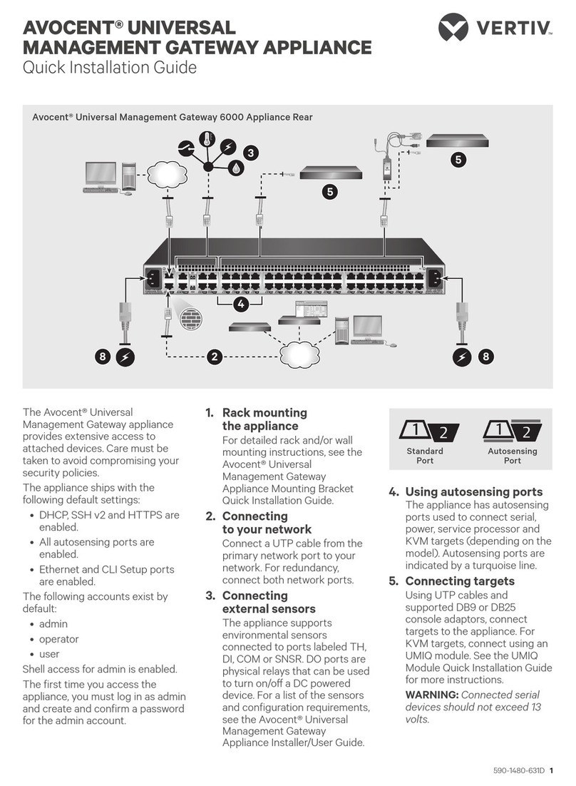
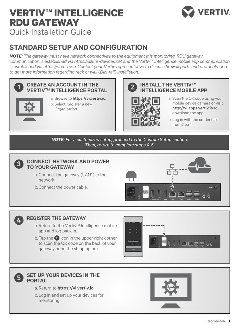
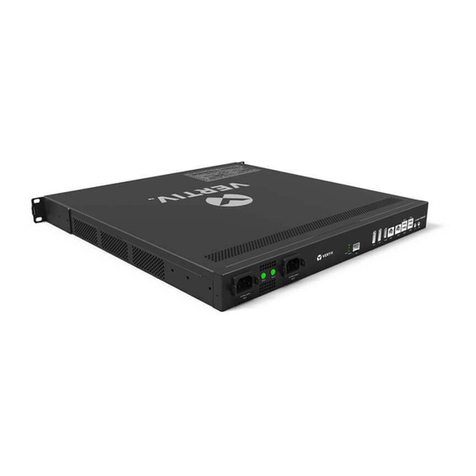
Vertiv Avocent Installation and maintenance instructions

Avocent® Universal Management
Gateway Appliance
Installer/User Guide

Technical Support Site
If you encounter any installation or operational issues with your product, check the pertinent section of this manual to see if
the issue can be resolved by following outlined procedures. For additional assistance, visit https://www.VertivCo.com/en-
us/support/.

TABLE OF CONTENTS
1 Product Overview 1
1.1 Features and Benefits 1
1.1.1 Secure access 1
1.1.2 Autosense 1
1.1.3 Web user interface (UI) 2
1.1.4 VGA and USB connections 2
1.1.5 CLI setup port 2
1.1.6 IPv4 and IPv6 support 2
1.1.7 Security 3
1.1.8 Data logging, notifications, alarms and data buffering 3
1.1.9 Power management 3
1.1.10 Auto discovery 3
1.1.11 Control of virtual media and smart card-capable appliances 3
1.1.12 Flexible users and groups 3
1.1.13 Avocent® DSView™ management software plug-in 3
2 Installation 5
2.1 Supplied with the Appliance 5
2.2 Rack and Wall Mounting 5
2.2.1 Rack mounting 5
2.2.2 Cabling installation, maintenance and safety tips 6
2.3 Connecting the Hardware 6
2.3.1 Appliance connectors 6
2.3.2 Connecting targets 8
2.4 Turning On the Appliance 9
2.5 Verifying the Connections 9
2.5.1 Front and rear panel power status LEDs 9
2.5.2 Rear panel Ethernet connection LEDs 10
2.5.3 Rear panel autosensing/dedicated IP port LEDs 10
2.6 Configuring the Appliance 10
2.7 Configuration Example 10
2.7.1 Using Telnet or SSH to access a serial target 12
3 Initial Appliance Setup 15
3.1 Connecting to Your Network 15
3.2 Assigning an IPAddress 15
3.3 Connecting Locally or Through the Console Port 15
3.4 Setting Up Your Network 16
3.5 Firewall 16
3.5.1 Port requirements 17
4 Web User Interface 19
4.1 Web UI Overview 19
4.2 Using the Sidebar 20
4.2.1 Admin role 20
4.2.2 Operator role 20
4.2.3 User role 20
4.3 Tabs 21
4.3.1 Targets 21
4.3.2 Sensors 21
Vertiv | Avocent® Universal Management Gateway Appliance Installer/User Guide | i

4.3.3 Events 21
4.3.4 Administration 21
5 Administration 23
5.1 Appliance Settings 23
5.1.1 SSH 23
5.1.2 Help File 24
5.1.3 Email Settings 24
5.2 Defaults 24
5.3 Network Settings 24
5.3.1 Network modes 24
5.3.2 Bridge Group Configuration 25
5.3.3 Hosts 26
5.3.4 Routes 26
5.3.5 OSPF and BGP 27
5.3.6 Network Share 28
5.4 Users 28
5.4.1 User role group 28
5.4.2 Users group 29
5.5 Password Policy 29
5.6 Preemption Levels 29
5.6.1 Adding a user 30
5.6.2 Authentication 30
5.6.3 User Target Access 32
5.6.4 User Target Rights 32
5.6.5 Groups 32
5.7 Targets 36
5.7.1 Licenses 36
5.7.2 Port configuration 36
5.7.3 SPmanagement 43
5.7.4 Firmware upgrade and repository 45
5.7.5 Serial management 48
5.7.6 PDUmanagement 51
5.8 Asset Location 52
5.8.1 RFIDtag 52
5.8.2 KVM management 53
5.8.3 Target groups 59
5.9 Startup 59
5.10 Firmware 60
5.10.1 Backing up and restoring appliance configuration 60
5.11 USBDevices 61
5.12 Sensors 61
5.12.1 Com Digital Input 62
5.12.2 Digital inputs 63
5.12.3 Environment 63
5.12.4 RS485environment sensor 64
5.12.5 PDU Temperature Sensors Delta 64
6 Monitoring 67
6.1 Notification destinations 67
6.1.1 SNMP 67
Vertiv | Avocent® Universal Management Gateway Appliance Installer/User Guide | ii

6.1.2 Syslog 67
6.1.3 Email 68
6.1.4 Digital Output 69
6.2 Sessions 69
6.3 Support 69
6.4 Security 69
6.4.1 Certificate 70
6.4.2 FIPS140-2 70
6.4.3 Address Filter 71
6.5 Firewall and NAT 73
6.5.1 Interfaces 73
6.5.2 Defined networks 74
6.5.3 Hosts 75
6.5.4 Services 76
6.5.5 Policy 77
6.5.6 1-to-1 NAT 83
7 Targets 85
7.1 Service Processors 86
7.1.1 Properties 86
7.1.2 System 86
7.1.3 SEL 87
7.1.4 Sessions 87
7.1.5 Power 88
7.1.6 Sensors 88
7.1.7 Logs 88
7.1.8 IML 88
7.1.9 System Info 88
7.1.10 Node Manager 88
7.2 UMIQ Modules 89
7.3 KVM Session Optimization 89
7.4 Serial Console 90
7.5 PDU 90
7.5.1 Properties 90
7.5.2 Outlets 90
7.5.3 Overview 90
7.5.4 Current, Voltage, Power Consumption, Energy Consumption 91
7.5.5 Settings 91
7.6 Power Outlet 92
7.7 Accessible Targets 92
8 Sensors and Events 93
8.1 Sensors 93
8.2 Events 93
8.2.1 Fan 93
8.2.2 Temperature 93
8.2.3 Power 93
8.2.4 CPU and disk usage 93
9 Appendices 95
Appendix A: Technical Specifications 95
Appendix B: Installation Checklist 96
Vertiv | Avocent® Universal Management Gateway Appliance Installer/User Guide | iii

Appendix C: Forgotten Password 97
Appendix D: Booting from the Network 98
Appendix E: Creating an SPFile 99
Appendix F: Troubleshooting SPs 100
Appendix G: Appliance Troubleshooting 101
Appendix H: Troubleshooting From the Appliance Shell 103
Appendix I: IPMasquerading for 1-to-1 NAT 105
Appendix J: Firewall and NATConfiguration Scenarios 106
Appendix K: Video Resolution 108
Vertiv | Avocent® Universal Management Gateway Appliance Installer/User Guide | iv

1 PRODUCT OVERVIEW
The Avocent® Universal Management Gateway appliance serves as a single point for secure local and remote access and
administration of target devices. The Avocent® Universal Management Gateway appliance supports secure remote data
center management and out-of-band management of IT assets from any location worldwide. It provides keyboard, video
and mouse (KVM) capabilities and can also remotely perform server management tasks, including power control and
console access, on managed target devices. Multiple administrators can be logged into the appliance at the same time and
can use the web user interface (UI), the command line interface (CLI) or DSView™ 4 management software to access and
configure the appliance.
NOTE: All instances of DSView™ software in this document refer to DSView™ software version 4.5 or higher.
The Avocent® Universal Management Gateway appliance combines KVM over IP, Service Processor Management (SPM)
and access and serial console management access. It gives you flexible target device management control and secure
remote access from anywhere at anytime.
1.1 Features and Benefits
1.1.1 Secure access
You can securely access the appliance through the following local (analog console port) and remote (digital IP) options:
•LAN/WAN IP network connection.
•Serial target device connection. An authorized user can make a Telnet, SSH v1, SSH v2 or raw connection to a
target device. For Telnet or SSH to be used for serial target device connections, the Telnet or SSH service
must be configured in the Security Profile that is in effect.
•Console connection. An administrator can log in either from a local terminal or from a computer with a terminal
emulation program that is connected to the console port and can use the CLI.
1.1.2 Autosense
The Avocent® Universal Management Gateway 2000 appliance has eight autosensing ports that can be used for either
service processor (SP)or serial connectivity and management. It has an additional 32 RJ45 ports which are intended solely
for SP connectivity and management. The Avocent® Universal Management Gateway 4000 and 6000 appliances have 40
autosensing ports that can be used for service processor (SP)or serial connectivity and management.
Ports that support autosensing are designated on the back of the appliance with a small turquoise line next to the port
number. Ports indicate which mode of operation is currently active with a green or amber connection LED. By default, all
ports capable of autosensing are in automode. It is recommended to leave the port set to autosense. This is indicated by
having both the green and amber LEDs illuminated. If a port is statically set to one of the two modes, the corresponding
LED will be the only one illuminated.
Figure 1.1 Autosensing Port
Network and serial mode
The autosensing ports can operate in network or serial mode. Each major mode has sub modes called port classes. The
network port class is for network or SP connections. The port will autosense network targets but will need to be manually
configured for SP connected targets. The serial port class is for console connections or PDU connections. By default, the
serial port class will autosense to a console connection and will need to be manually configured for a Power Distribution Unit
(PDU) connection. The ports will autosense and switch to the appropriate mode depending on the target attached to the
appliance.
Vertiv | Avocent® Universal Management Gateway Appliance Installer/User Guide | 1

When a port is in network mode, the green LED will be illuminated. The appliance will provide an IP address to the network
device attached to it. It is only intended to be connected to the device to be managed or accessed. The appliance will not
function as a traditional network switch or common network access firewall. It is a special purpose appliance intended for
target device access and management.
CAUTION: Since the appliance issues IP addresses using DHCP, they could conflict with a production DHCP
infrastructure. Proper VLAN segmentation must be assigned on the network to avoid this conflict.
IP addresses can also be assigned statically to SPs, and the appliance can scan IP ranges to discover them.
When a port is in serial mode, the amber LED will be illuminated. The appliance will assign the console port class by default
and auto-detect whether to apply the Avocent® or Cisco® soft pinout. The speed, flow control, parity and data-size are all
predefined for connectivity to standard RS232 server consoles but can be modified on a per-port basis. In addition to
console mode, a supported Avocent® PDU can be connected to and managed from the appliance.
1.1.3 Web user interface (UI)
Users and administrators can perform most tasks through the web UI(accessed with HTTPS). The web UI runs in Microsoft
Internet Explorer® and Mozilla Firefox® browsers on any supported computer that has network access to the appliance.
An administrator can use the web UI to create user accounts, authorize groups and configure security and ports. Authorized
users can access connected devices through the web UI to troubleshoot, maintain, cycle power, or to reboot connected
devices and change their password. For more information on the web UI, see Web User Interface on page 19.
1.1.4 VGA and USB connections
Standard VGA and USB connections can be used to attach an LCD tray. These ports are located on the front of the
appliance. The VGA console port can be used for launching sessions to targets or for performing NetBoot firmware
recoveries. The USB ports are used for connecting USB keyboard, mouse, smart card reader, CD, DVD or mass storage
devices.
KEY COMBINATION OPERATION
Alt + Tab Toggle to next view in a cyclic list
Alt + F1 View web UI
Alt + F2 View User Shell
Alt +Esc Close current view and session
Table 1.1 VGA Console Hotkeys
NOTE: Press ALT-F1 during the appliance boot progress screen to display verbose output.
1.1.5 CLI setup port
The serial setup port provides access to the CLI and Shell. The appliance does not support root access to the Bash Shell.
The CLI is intended for managing and configuring the appliance.
1.1.6 IPv4 and IPv6 support
The appliance supports dual stack IPv4 and IPv6 protocols. The administrator can use the web UI or CLI to configure
support for IPv4 and/or IPv6 addresses. The following list describes the IPv4 and IPv6 support provided in the appliance:
•DHCP
•DSView software integration
•Ethernet interfaces, GB1 (eth0) and GB2 (GB2 (eth1))
•Firewall (IP tables)
•HTTPS
•Linux kernel
•Remote authentication: AD and LDAP servers
Vertiv | Avocent® Universal Management Gateway Appliance Installer/User Guide | 2

•SSH and Telnet access
•Syslog server
NOTE: Remote authentication NFS, NIS and IPSec are not supported with IPv6.
1.1.7 Security
The Security settings allow administrators to determine which network services are enabled on the appliance.
1.1.8 Data logging, notifications, alarms and data buffering
An administrator can set up data logging, notifications and alarms to alert administrators of problems with email and syslog
messages. An administrator can also store buffered data locally. Messages about the appliance and connected servers or
devices can also be sent to syslog servers.
1.1.9 Power management
The Avocent® Universal Management Gateway appliance enables users who are authorized for rack power distribution units
(PDU) and service processor (SP) power management to turn power on, turn power off and reset servers via their embedded
SP devices plugged into a connected rack PDU.
1.1.10 Auto discovery
An administrator can enable auto discovery to find the hostname of a target connected to a port. Auto discovery’s default
probe and answer strings have a broad range. An administrator can configure site-specific probe and answer strings. Auto
discovery can also be configured through the DSView™ software.
Supported SPs
The appliance supports rack and blade server SPs from the following vendors: Dell®, HP, IBM®, Cisco®, Fujitsu®, Oracle® Sun
and additional IPMI implementations. For a complete list of SPs supported by your appliance, visit
https://www.VertivCo.com to see the release notes that match your appliance firmware version.
1.1.11 Control of virtual media and smart card-capable appliances
The Avocent® Universal Management Gateway appliance allows you to view, move or copy data located on virtual media to
and from any target device. Manage remote systems more efficiently by allowing operating system installation, operating
system recovery, hard drive recovery or duplication, BIOS updating and target device backup.
Smart cards such as the Common Access Card (CAC) can be used to store identification and authentication to enable
access to computers, networks and secure rooms or buildings.
Virtual media and smart card readers can be connected directly by using USB ports located on the appliance. In addition,
virtual media and smart card readers may be connected to any remote workstation that is running the remote web UIor
DSView™ management software and is connected to the appliance using an Ethernet connection.
1.1.12 Flexible users and groups
An account can be defined for each user on the appliance or on an authentication server. An administrator has an account
by default and can add and configure other user accounts. Access to ports can be optionally restricted based on
authorizations an administrator can assign to custom user groups.
1.1.13 Avocent® DSView™ management software plug-in
The DSView™ management software may be used with the appliance to allow IT administrators to remotely access, monitor
and control target devices on multiple platforms through a single, web-based user interface. DSView™ software proxy and
SSHPass-through features enable convenient and secure remote access for LAN and WANclients. For more information,
see the Avocent® DSView™ 4 Management Software Plug-In for the Avocent® Universal Management Gateway Appliance
Technical Bulletin.
Vertiv | Avocent® Universal Management Gateway Appliance Installer/User Guide | 3

Vertiv | Avocent® Universal Management Gateway Appliance Installer/User Guide | 4
This page intentionally left blank.

2 INSTALLATION
Before installing your Avocent® Universal Management Gateway appliance, refer to the following list to ensure you have all
items that shipped with it, as well as other items necessary for proper installation.
2.1 Supplied with the Appliance
•Appliance Quick Installation Guide (QIG)
•Avocent® Universal Management Gateway Appliance Mounting Bracket Quick InstallationGuide (QIG)
•Power Cords
•RJ45 to DB9F cross adaptor
•Mounting brackets and screws
•Safety and Regulatory Statements Guide
2.2 Rack and Wall Mounting
You can mount the appliance in a rack or cabinet; or, using the optional wall-mounting kit, you can mount it on a wall.
2.2.1 Rack mounting
To rack mount the appliance:
1. Remove the four black screws from each side of the Avocent® Universal Management Gateway appliance.
2. Position each bracket so it is not covering the side vents of the appliance.
3. Secure the mounting brackets to the appliance using the eight chrome screws supplied with the appliance.
4. Loosely attach the two slide-rail brackets to the front of the rack using the appropriate screws for your rack.
5. From the rear of the rack, slide the appliance into the same U position where the slide rails are mounted. Ensure
that both slide rails are securely inserted into the appliance bracket.
6. Tighten the rack screws for both the appliance bracket and the slide rails.
Figure 2.1 Bracket Connections for Rack Mount Configuration
For more information, see the Avocent® Universal Management Gateway Appliance Mounting Brackets Quick Installation
Guide that is included with your product.
Vertiv | Avocent® Universal Management Gateway Appliance Installer/User Guide | 5

2.2.2 Cabling installation, maintenance and safety tips
WARNING! To avoid potentially fatal shock hazard and possible damage to equipment, please observe the
following precautions.
The following is a list of important safety considerations that should be reviewed prior to installing or maintaining your
cables:
•Dress the cables neatly with cable ties, using low to moderate pressure. Do not overtighten ties.
•If bending the cable is necessary, make it gradual with no bend sharper than a one inch radius. Allowing the
cable to be sharply bent or kinked can permanently damage the cable’s interior.
•Cross-connect cables where necessary, using rated punch blocks, patch panels and components. Do not splice
or bridge cable at any point.
•Keep UTP cable as far away as possible from potential sources of EMI, such as electrical cables, transformers
and light fixtures. Do not tie cables to electrical conduits or lay cables on electrical fixtures.
•Always test every installed segment with a cable tester. Toning alone is not an acceptable test.
•Always install jacks so as to prevent dust and other contaminants from settling on the contacts. The contacts of
the jack should face up on the flush mounted plates, or left/right/down on surface mount boxes.
•Always leave extra slack on the cables, neatly coiled in the ceiling or nearest concealed location. Leave at least
five feet at the work outlet side and 10 feet at the patch panel side.
•Choose either 568A or 568B wiring standard before beginning. Wire all jacks and patch panels for the same
wiring scheme. Don’t mix 568A and 568B wiring in the same installation.
•This product is not intended to be connected directly or indirectly by any means whatsoever to interfaces of
public switched telecommunications networks (PSTN).
•Always obey all local and national fire and building codes. Be sure to firestop all cables that penetrate a
firewall. Use plenum rated cable where it is required.
•Do not disable the power grounding plug. The grounding plug is an important safety feature.
•Plug the power cord into a grounded (earthed) outlet that is easily accessible at all times.
•Disconnect the power from the product by unplugging the power cord from either the electrical outlet or the
product. The AC inlet is the main disconnect for removing power to this product. For products that have more
than one AC inlet, to remove power completely, all AC line cords must be disconnected.
•This product has no user-serviceable parts inside the product enclosure. Do not open or remove product cover.
CAUTION: This appliance contains an internal battery that is used for the real-time clock. This battery is not
a field replaceable item, and replacement should not be attempted by a user. If real-time clock errors occur
and the battery is suspected, visit http://www.VertivCo.com/support or contact the Vertiv™ Technical
Support location nearest you.
WARNING! For Service Personnel Only - There is a risk of explosion if the battery is replaced with an incorrect
type. Dispose of used batteries according to the manufacturer’s instructions.
•This product is for use with other products that are Listed or Certified by a Nationally Recognized Testing
Laboratory (NRTL).
2.3 Connecting the Hardware
2.3.1 Appliance connectors
The following figure shows the connectors on the front of the appliance.
Vertiv | Avocent® Universal Management Gateway Appliance Installer/User Guide | 6

Figure 2.2 Front of the Appliance
ITEM DESCRIPTION
1 LED
2 Console Port
3 USB Connections
4 Analog Video Port
Table 2.1 Connectors on the Appliance Front
The following figure shows the rear connectors on the appliance.
Figure 2.3 Rear of the Appliance
ITEM DESCRIPTION
1 Power supplies.
2 Power Indication LED.
3GB2 (eth1) 10/100M/1G Ethernet port. Can be
connected to a second network or used for failover.
4 Sensors.
5
Autosensing ports. On the Avocent® Universal
Management Gateway 4000 and 6000 appliances,
all ports are autosensing. On the Avocent®
Universal Management Gateway 2000 appliance,
the eight ports on the left are autosensing and the
other 32 are dedicated.
Table 2.2 Connectors on the Appliance Rear
Vertiv | Avocent® Universal Management Gateway Appliance Installer/User Guide | 7

2.3.2 Connecting targets
Service processor
Use a UTP cable to connect a service processor to either an autosensing or a dedicated port on the appliance. See Port
configuration on page 36 for more information on how to set up service processors.
Serial
Use a UTP cable and a DB9 or DB25 console adaptor, as needed, to connect a serial target to an autosensing port on the
appliance.
The appliance supports both the Avocent® and Cisco® serial port pinout configuration. The port will autosense the pinout.
To connect serial devices and PDUs:
Make sure the crossover cable used to connect a device has the same pinout type that is configured in the software for the
port (either Avocent® or Cisco®).
1. Make sure the devices to be connected are turned off.
2. Use a UTP crossover cable to connect the devices to the appliance, using an adaptor, if necessary.
NOTE: To comply with EMC requirements, use shielded cables for all port connections.
WARNING! Do not turn on the power on the connected devices until after the appliance is turned on.
To daisy chain PDUs to the appliance:
NOTE: This procedure assumes you have one PDU connected to a port on the appliance.
1. Connect one end of a UTP cable with RJ45 connectors to the OUT port of the connected PDU.
2. Connect the other end of the cable to the IN port of the chained PDU. Repeat both steps until you have
connected the desired number of PDUs.
NOTE: For performance reasons, do not connect more than 128 outlets per serial port.
See Port configuration on page 36 for more information on how to set up serial targets.
KVM
If your appliance supports KVM connections, use a UTP cable and a UMIQmodule to connect a KVMtarget to an
autosensing port on the appliance.
Vertiv | Avocent® Universal Management Gateway Appliance Installer/User Guide | 8

Figure 2.4 UMIQModule Configuration
The UMIQ-v1 module has a single RJ45 port to connect to the appliance. The UMIQ-v2 module has two RJ45 ports. You can
connect either one to the appliance and the other to a dedicated service processor port on the server. The cable length can
be up to 100 meters long.
See KVM management on page 53 for more information about KVMtargets.
2.4 Turning On the Appliance
The appliance is supplied with dual power supplies.
To turn on the appliance:
1. Plug the power cables into the appliance and into a power source.
2. Turn on the connected devices.
2.5 Verifying the Connections
2.5.1 Front and rear panel power status LEDs
The front panel of appliance has a dual-color general status LED that may illuminate:
•The LED illuminates green when the appliance is turned on and operating normally.
•The LED blinks green when the appliance is booting.
•The LED illuminates amber if a fault condition occurs, such as power supply failure, elevated ambient
temperature or fan failure. The LED will continue to illuminate amber as long as the failure persists.
Vertiv | Avocent® Universal Management Gateway Appliance Installer/User Guide | 9

•The LED blinks amber when the appliance is shutting down. Once the LEDis off, it is safe to unplug the power
cords.
2.5.2 Rear panel Ethernet connection LEDs
On the appliance, the rear panel features two LEDs where the green LEDindicates Ethernet connection status:
•The solid green LEDdenotes an Ethernet link has been established.
•The blinking green LEDdenotes Ethernet activity.
•The solid amber LEDdenotes a target session is active.
•No LEDs illuminated denotes no activity.
2.5.3 Rear panel autosensing/dedicated IP port LEDs
The rear panel of the appliance features two LEDs, green or amber:
•If both LEDs are illuminated, autosensing is enabled.
•The green LED illuminates when there is a KVM or SP connection.
•The amber LED illuminates when there is a serial connection.
2.6 Configuring the Appliance
The appliance may be accessed through the CLI, console or Ethernet ports. All terminal commands are accessed through a
terminal or PC running terminal emulation software.
NOTE: To configure the appliance using Avocent® DSView™ software, see the Avocent® DSView™ 4 Management
Software Installer/User Guide. To configure using the appliance's web UI, see Administration on page 23. To
configure using Telnet or SSH, see the Avocent® Universal Management Gateway appliance Command Reference
Guide.
To connect a terminal to the appliance:
1. Using a null modem cable, connect a terminal or a PC that is running terminal emulation software to the
console port on the front panel of the appliance. An RJ45 to DB9 (female) cross adaptor is provided.
The terminal settings are 9600 bits per second (bps), 8 bits, 1 stop bit, no parity and no flow control.
2. Turn on the appliance. When the appliance completes initialization, the terminal will display the login banner
plus the login prompt.
2.7 Configuration Example
The following graphic and table illustrate a typical appliance configuration.
Vertiv | Avocent® Universal Management Gateway Appliance Installer/User Guide | 10

Figure 2.5 Typical Avocent® Universal Management Gateway Appliance Configuration
Vertiv | Avocent® Universal Management Gateway Appliance Installer/User Guide | 11

ITEM DESCRIPTION ITEM DESCRIPTION
1 Power supplies 11 DSView server
2 Ethernet connection 12 Remote authentication
3 User 13 PCclient
4 External sensors connection 14 USB media
5 Autosensing ports for serial or service processor targets 15 RJ45 serial setup port
6 UMIQ modulefor KVMconnection 16 DB9 com port
7 Target server (VGA/USB) 17 PCfor local configuration
8 Firewall 18 USBconnection (keyboard, mouse or media)
9 Ethernet connection 19 VGAconsole port
10 Local Area Network (LAN) 20 LCDtray for local configuration and access
Table 2.3 Typical Avocent® Universal Management Gateway Appliance Configuration Descriptions
2.7.1 Using Telnet or SSH to access a serial target
An authorized user can use a Telnet or SSH client to make a connection directly to the console of a serial target if all of the
following are true.
The Telnet or SSH:
•protocol is enabled for network service in the security profile
•protocol is configured for the port
•client is available, and it is enabled on the computer from which the connection is made
To use Telnet to connect to a target through a serial port:
For this procedure, you need the username configured to access the serial port, the target name (for example, 14-35-60-p-1),
device name (for example, ttyS1), TCP port alias (for example, 7001) and the hostname of the appliance or its IP address.
To use a Telnet client, enter the information in the dialog boxes of the client.
-or-
To use Telnet in a shell, enter the following command:
# telnet [
hostname
|
IP_address
]
login: [username]:[targetname | device_name]
-or-
# telnet [hostname | IP_address] TCP_Port_Alias
login: [username]
To close a Telnet session:
Enter the Telnet hotkey defined for the client. The default is Ctrl + q to quit.
To use SSH to connect to a target through a serial port:
For this procedure, you need the username configured to access the serial port, the target name (for example, 14-35-60-p-1),
TCP port alias (for example, 7001), device name (for example, ttyS1), and the hostname of the appliance or IP address.
To use an SSH client, enter the information in the dialog boxes of the client.
-or-
To use SSH in a shell, enter the following command:
Vertiv | Avocent® Universal Management Gateway Appliance Installer/User Guide | 12

ssh -l [username]:[target_name] [hostname | IP_address]
-or-
ssh -l [username]:[device name] [hostname | IP_address]
-or-
ssh -l [username:TCP_Port_Alias] [hostname | IP_address]
To close an SSH session:
At the beginning of a line, enter the hotkey defined for the SSH client followed by a period. The default is ~.
Vertiv | Avocent® Universal Management Gateway Appliance Installer/User Guide | 13

Vertiv | Avocent® Universal Management Gateway Appliance Installer/User Guide | 14
This page intentionally left blank.
Other manuals for Avocent
1
Table of contents
Other Vertiv Gateway manuals