Lobaro LOB-GW-HYB-WMBUS User manual

LOB-GW-HYB-WMBUS
Wireless M-Bus Gateway V3
Quick Start Guide (EN)
Manufacturer
í
Lobaro GmbH | Stadtdeich 7 | D-20097 Hamburg | Germany
support@lobaro.de | www.lobaro.de
Important notes
^
This document is a quick reference guide. A sup-
plementary product description is available online at
https://doc.lobaro.com
.
,
The device is powered by an internal, replaceable 3.6V lithium
battery (Li-SOCl2), which is subject to transport restrictions.
Hazardous material class: 9A. The applicable transport regula-
tions must be met when transporting the device incl. inserted
battery. The battery must not be connected during transport!
The test certicates for the approved batteries are available on
request.
,
This product must be installed professionally and in accordance
with the specied installation guidelines and may therefore only
be installed by trained and qualied personnel. For installa-
tion in structures with increased re protection requirements,
e.g. staircases, escape routes, the installation company or the
qualied personnel must ensure that the specic requirements
according to local building regulations are fullled!
,
These instructions must be read carefully before initial opera-
tion, followed and kept for the entire service life of the device.
Intended use
The
Lobaro Wireless M-Bus Gateway V3
receives data telegrams from up
to 500 utility meters with standardized 868 MHz wireless M-Bus interface
and forwards them downstream via NB-IoT cellular radio or alternatively
LoRaWAN to the Internet for further processing or evaluation.
In addition to the unidirectional wireless M-Bus modes
C1, T1 and S1
,
the proprietary
Sensus RF
radio protocol is also supported by the radio
receiver in the gateway.
The previously received meter data is transferred to the Lobaro IoT plat-
form, optionally encrypted via DTLS, and can be viewed there or down-
loaded as a CSV le. Alternatively, the connection of other downstream
third-party systems via standardized APIs from the Lobaro platform is
easily possible.

,
The device is intended exclusively for the aforementioned pur-
pose. An application other than previously described or a mod-
ication of the gateway are considered as non-intended use and
must be requested in writing in advance as well as specically
approved.
Mode of operation
1. The gateway is in energy-saving mode for the majority of its operating
time.
2. The device wakes up at freely congurable intervals ('CRON param-
eters').
3. Encrypted or unencrypted Wireless M-Bus (868 MHz) telegrams
are received for the congured time duration (among others
'cmodeDurSec parameter') and buered unchanged in the internal
memory.
4. Meter reception can be restricted with lters to specic device IDs,
types or 'CI elds'.
5. After the congured period of time, the collection of meter data by
radio is stopped again.
6. The data is sent via NB-IoT cellular radio or LoRaWAN to the down-
stream IoT platform or LoRaWAN network server on the Internet.
7. The platform decrypts (on demand) the consumption data with stored
keys.
8. The consumption values or meter telegrams are available in table
view, as CSV download or via standardized APIs.
Device components
Figure 1: Device components
1. Battery connector (JST-XH 2Pin)
2. SIM card socket
3. Reset button
4. Status LED (RGB)
5. Connector for USB conguration adapter (Art.: #8000005)
6. MicroSD card socket
7. Connector for internal PCB antenna
8. Battery (3.6V | 13Ah) incl. loop tape (Art.: #3000581)
9. Pressure compensation element (PCE)

Initial operation
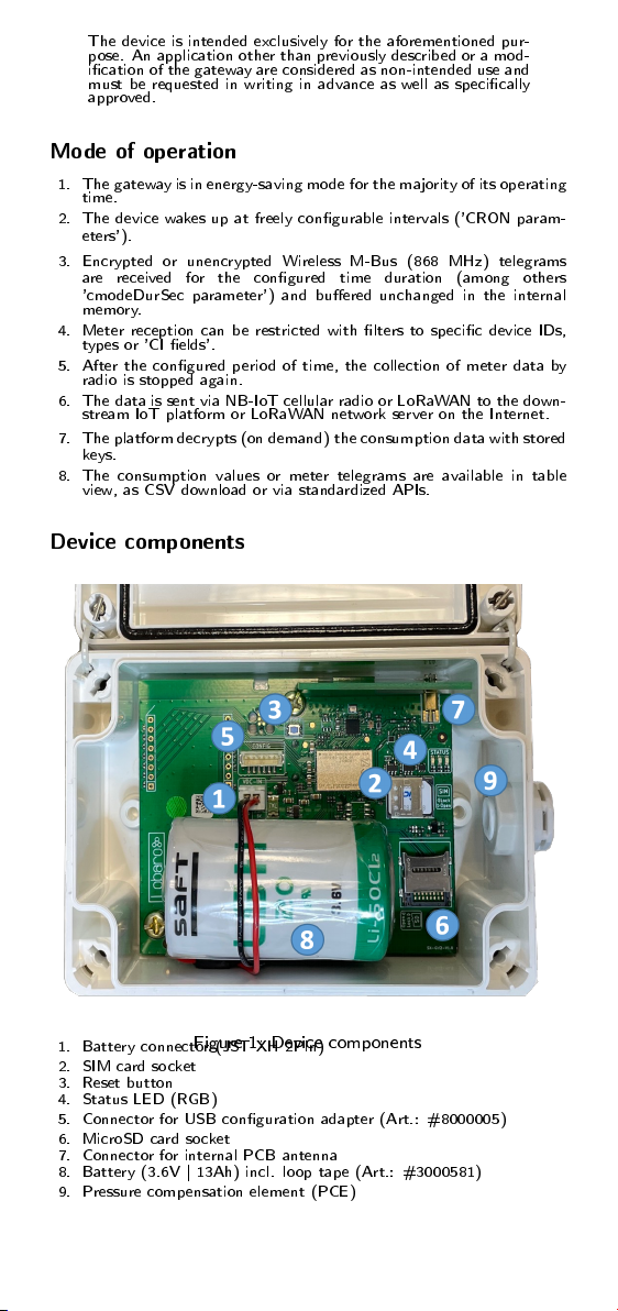
To commission the gateway, a suitable SIM card must be inserted in the
socket at position (2) if mobile radio is to be used for data upload instead
of LoRaWAN. To do this, rst slide the cover lock of the socket to the
right and then open it upwards. During insertion, it is essential to ensure
that the battery (1) is not connected. After inserting the SIM card, the
cover must be folded down and the lock must be closed again by sliding
it to the left.
The associated battery is equipped with loop tape, which is to be attached
to the velcro hooks of the device at position (8) when inserting it. Make
sure that the connecting cable of the battery is routed around the battery
body as shown in Fig.1. Then connect the plug connector of the battery
to the reverse polarity protected socket at position (1).
If the device was without power for more than 24 hours, e.g. at delivery,
it starts with the pre-congured parameters after connecting the battery
and initiates an initial collection of metering data with downstream upload
of the data via LoRaWAN or mobile radio. The device conguration of
the delivery state can be viewed via the downstream platform or was
transmitted in advance in the form of a digital delivery note.
The reset button (3) can be used at any time to reproduce the same
behavior as with the aforementioned connection of the battery after 24
hours without voltage, e.g. to start a control readout during installation
or when changing the battery.
By means of the status LEDs (4) dierent operating modes of the rmware
can be read. The dierent blinking patterns are described in the online
manual, available at
https://doc.lobaro.com
.
The socket for an SD card (6) is suitable for holding a corresponding
memory card. The locking mechanism works analogously to the SIM
card.
,
Only 3.6V batteries approved by Lobaro may be used with the
gateway. The use of other batteries, especially without velcro
u, is not permitted, as there would be no sucient protection
of the battery in the housing.
,
Only antennas approved by Lobaro may be connected to the
MMCX antenna connector (7)!
ð
The storage functionality for SD cards (6) may not be supported
by all rmware versions.
ð
The SIM card used must be activated for NB-IoT or LTE-M1
networks. The gateway conguration of the LTE connection
(operator, APN, band) must match the SIM card used!
Gateway conguration
Reading and adjusting the gateway conguration is possible via the 6-pin
conguration connector (5) and the separately available Lobaro USB con-
guration adapter in combination with the free PC-based 'Lobaro Main-
tenance Tool' for Windows, Linux and MacOS.
Alternatively, if the network parameters are congured correctly, the con-
guration changes can also be made 'over-the-air' via the Lobaro IoT
platform.
ð
Details of the gateway conguration and available parameters
can be found in the online manual at
https://doc.lobaro.com
.
Proper mounting and housing dimensions
The cover of the gateway is secured via four quick-release screws. These
screws are loosened or tightened via a 90
°
turn. In addition, the housing
has a lid loss protection.
The gateway is securely fastened to a wall or ceiling with the cover open
using the four fastening points marked in red in Figure 3 and 4 mm anchor
screws. For example, in a solid brick wall, 4 mm anchor screws with a
length of 50 mm can be used with 38 mm long dowels with a diameter of
6 mm to ensure a good hold.
After successful wall mounting, the cover must be closed again.

Figure 2: Quick-release screws lid (open | close)
,
When opening the housing lid, the quick release screws must
not be turned more than a 1/4 turn. Otherwise the screws may
break o!
,
The gateway must be securely screwed to a wall/ceiling using
four suitable M4 screws and wall anchor, cf. red marking in
gure 3.
Figure 3: Housing measurements [mm]
,
When selecting the installation site, it is essential to ensure
that the specied ambient conditions (see Technical data) can
be maintained at all times.
,
The mounted pressure compensation element (9) increases the
total width of the gateway from 122 mm in gure 3 to a total
of 130 mm.
ð
The pressure compensation element (9) and the IP66 housing
protection class allow the gateway to be operated outdoors.
Simplied CE declaration
Lobaro GmbH hereby declares that the LOB-GW-HYB-
WMBUS is in compliance with Directives 2014/53/EU and
2011/65/EU. The full text of the EU Declaration of Confor-
mity is available at the following Internet address:
https://doc.lobaro.com

Technical specications
General
Type LOB-GW-HYB-WMBUS
Purchase name Wireless M-Bus Gateway V3
Input Voltage 3.3V to 5V, 3.6V (standard)
Item number 8000162
Metering
Wireless M-Bus S1, C1/T1 Mode
RX frequencies 868.3 MHz, 868.95 MHz
Standard DIN EN 13757-4
Proprietary mode Xylem SensusRF (BubbleUP)
Typ. range 30 m (Indoor), 2-3 oors
Typ. range 100 m (Outdoor), open space
Memory capacity 500 telegrams á 100 bytes
Whitelist lter ID, M-Field, CI-Field, Type
Conguration collection duration and intervals
Cellular
LTE networks Cat-NB1, Cat-NB2, Cat-M1
LTE bands B3, B8, B20
TX power
≤
23 dBm
Typ. range network-dependent
SIM card 4FF (Nano-SIM)
Data transfer CoAP via UDP
Encryption DTLS (optional)
Data format CBOR bzw. JSON
LoRaWAN
Protocol Class A LoRaWAN 1.0.2 EU868
TX power
≤
14 dBm
Activation Over-the-air activation (OTAA)
Typ. range up to 2 km, urban
Typ. range up to 10 km, open space
Antenna
Internal type multiband PCB monopoles
Ext. connector on request
Battery
Approved type SAFT LSH20
Voltage 3.6V
Other types on request
Chemistry Li-SOCl2
Capacity
≤
13 Ah
Cont. current
≤
1.8 A
Weight
≤
120 g
Connector JST-XH 2-Pin
Mounting 3M hook and loop tape
Power
Normal / Idle
≤
11 mW
depends RX Metering
≤
33 mW
on RX LoRa
≤
33 mW
operating TX LoRa
≤
110 mW
mode RX NB-IoT
≤
162 mW
TX NB-IoT
≤
1.6 W
Sleep
≤
36
µ
W
Housing
Measurements 130 x 82 x 55 mm
³
(incl. PCE)
Material Polycarbonate
Screws stainless steel V2A
Weight
≤
340 g (incl. battery)
Flammability class 960
°
C V-2 (as per UL94)
Protection class IP66 (0.3 bar / 30 seconds)
Color white
Impact-
resistance IK08
Environment
Rel. humidity 20...70 % (non-condensing)
Must be Operating temp. -20
°
C to 55
°
C
followed! Storage temp. 0
°
C to 30
°
C
Installation height
≤
2 m (above ground)
Installation height
≤
2000 m (above sea level)

Radio frequencies and bands used
Harmonized radio bands used by the gateway, max. occupied bandwidths
(BW) and transmission powers (TX power, EIRP). Unless otherwise indi-
cated, the specied frequencies are used for both the transmit (TX, UL)
and receive (RX, DL) directions.
Band Modulation BW Frequencies TX power
kHz MHz dBm
L LoRa 125 867.1, 867.3, 867.5,
867.7, 867.9 14
M LoRa 125 868.1, 868.3, 868.5 14
M LoRa 250 868.3 14
P LoRa 125 869.525 14
M FSK 200 868.3 Only RX
M FSK 200 868.42 Only RX
N FSK 200 868.95 Only RX
B8 Cat-NB1|2 200 UL:880...915,
DL:925...960 23
B20 Cat-NB1|2 200 UL:832...862,
DL:791...821 23
B3 Cat-NB1|2 200 UL:1710...1785,
DL:1805...1880 23
B8 Cat-M1 1800 UL:880...915,
DL:925...960 23
B20 Cat-M1 1800 UL:832...862,
DL:791...821 23
B3 Cat-M1 1800 UL:1710...1785,
DL:1805...1880 23
Proper disposal of this product
In Germany and for products delivered directly from Germany:
Due to the applicable regulations, the electrical and electronic
devices of Lobaro GmbH may not be disposed of via the public
collection points for electrical devices!
In order to create possibilities for the return of old devices,
we cooperate with several qualied recycling companies. If
a device manufactured by us has become an old device and
you would like to return it, please contact:
https://www.take-e-way.de/leistungen/
elektrogesetz-weee-elektrog/b2b-altgeraete-ruecknahme-entsorgung
and ll out the questionnaire.
In countries of the European Union outside Germany:
Information on correct disposal can be obtained from your dealer or the
responsible distributor.
Safety instructions Lithium batteries
Store protected from moisture
Keep out of reach of children
Do not heat above 85
°
C
Do not short circuit
Do not open or damage
Do not recharge
,
Batteries may only be replaced by qualied personnel. The
connector plug only ts in one position to ensure correct polar-
ity installation. Therefore, do not apply excessive force when
plugging in.
,
The battery may only be connected during regular operation.
Deep discharge due to persistent error conditions, e.g. if the
device cannot establish a connection or send data for long pe-
riods, must be avoided.
Warranty and guarantee
Warranty and guarantee claims can only be asserted if the device has been
used as intended and the technical specications and applicable technical
rules have been observed.
Last updated: 15.07.2022
Table of contents
Other Lobaro Gateway manuals