Intellian t110Q User manual

Marine Satellite Television Antenna System
t110W/t130W/t110Q/t130Q
Installation and Operation Manual


Serial number of the product
This serial number will be required for the all troubleshooting or service inquiries.
© 2017 Intellian Technologies Inc. All rights reserved.
Intellian and the Intellian logo are trademarks of Intellian Technologies, Inc.,
registered in the U.S. and other countries. t110W, t130W, t110Q and t130Q are
trademarks of Intellian Technologies, Inc. Intellian may have patents, patent
applications, trademarks, copyrights, or other intellectual property rights covering
subject matter in this document. Except as expressly provided in any written
license agreement from Intellian, the furnishing of this document does not give
you any license to these patents, trademarks, copyrights, or other intellectual
property. All other logos, trademarks, and registered trademarks are the property
of their respective owners. Information in this document is subject to change
without notice. Every effort has been made to ensure that the information in this
manual is accurate. Intellian is not responsible for printing or clerical errors.
Doc. No. UM-L3-170623-V2.6
Disclaimer
The information in this user manual is subject to change without prior notice
through a product life cycle. A printed version of the user manual is periodically
updated and may contain inaccuracies or omissions compared to the recent
product information. The most up-to-date information can be readily accessible on
a supplied USB memory stick or on our website at http://www.Intelliantech.com.

INDEX

5
INDEX
INTRODUCTION 9
Intellian t110W/t130W/t110Q/t130Q Introduction 10
Intellian t110W/t130W/t110Q/t130Q Features 11
Basic System Conguration 12
INSTALLING THE ANTENNA 13
System Package 14
Planning the Installation 19
Antenna Installation 23
INSTALLING THE ACU 31
Mounting the ACU 32
Connecting the System's Cables 34
PC to ACU Communication Setup 39
Wi-Fi Connection 41
OPERATING THE ACU 45
Introduction 46
Normal Mode 48
Setup Mode 52
Intallation Settings 55
Antenna Settings 58
Satellite Settings 69
System Settings 76
Aptus®81
Introduction to Aptus®82
Software Installation 83
PC to ACU Communication Setup 84
Toolbar Menus 87
System Property Status Dashboard 90
Work View Tabs 92
APTUS WEB 107
Introduction 110
Main Page 111
Antenna Settings 115
Firmware & Conguration 121
Administration 127
t110W/t110Q TECHNICAL SPECIFICATION 137
t130W/t130Q TECHNICAL SPECIFICATION 138
WARRANTY 139
APPENDIX: LIBRARY UPGRADE GUIDE 140
t110W/t130W/t110Q/t130Q – Marine Satellite Television System
6
CERTIFICATIONS

7

t110W/t130W/t110Q/t130Q – Marine Satellite Television System
8

9
INTRODUCTION
Intellian t110W/t130W/t110Q/t130Q
Introduction
Intellian t110W/t130W/t110Q/t130Q
Features
INTRODUCTION

t110W/t130W/t110Q/t130Q – Marine Satellite Television System
10
Intellian t110W/t130W/t110Q/t130Q
Introduction
The t-series is designed completely in-house, 3-axis stabilized platform available
both an Intellian exclusive WorldViewTM Low Noise Block down converter (LNB)
module and General-purpose Universal Quad LNB.
The t-series offers recreational and commercial boaters to achieve a new level of
satellite TV convenience, as well as unparalleled access to the greatest number of
channels at sea.
The Intellian t110W/t130W is the TV antenna capable of operating in all global
market without the need of changing the LNB unit inside of antenna's dome.
The Intellian t110Q/t130Q has the European dedicated linear LNB and provides
higher optimized gain for especially European waters.
Intellian's patented WRS (Wide Range Search) algorithm achieves fast signal
acquisition and pioneering DBT (Dynamic Beam Tilting) technology makes keeping
stable signal locking.
Designed to excel in all sea states and weather conditions, t110W/t130W and
t110Q/t130Q are tested to industry-leading standards for vibration and resonance
frequency as well as extreme.

11
INTRODUCTION
Intellian t110W/t130W/t110Q/t130Q
Features
Global Satellite Services Compatibility
Intellian t110W/t130W provides the ultimate convenience to connect you up to
thousands of Free TV, pay TV, Standard Denition, and high Denition programming
all over the world with one LNB module which incorporates multi (8) LO frequencies.
Hands-Free WorldViewTM LNB Module for t110W/t130W
The Intellian WorldViewTM LNB module is built on the highest stability of ±25 kHz and
capable of receiving multiband and multi-polarization satellite TV service around the
globe. Therefore, users don't need to manually change the LNB inside the antenna
dome each time the vessel crosses into a different satellite service region.
Universal Quad LNB Module for t110Q/t130Q
The Universal Quad LNB module is optimized for European waters using by Dual
Local Frequency (9.75GHz, 10.60GHz). It provides higher optimized gain for
especially European water.
Intelligent Signal Distributor
The embedded Quattro Switching Module(QSM) intelligently distributes different
tone signals to the correct ports on any legacy multi switches installed throughout
the ship. No need for reconguring anything below deck apart from the ACU.
DVB-S2 Digital TV Reception
Some of the HD TV services have moved to DVB-S2 transmission formats and there
will be more in the future. Thanks to Intellian's groundbreaking DVB-S2 digital TV
technology, now boaters are able to enjoy their favorite Sat TV entertainment at sea,
just like home.
Wide Elevation Range
The wide elevation range enables the antenna to have seamless signal reception
while the vessel is traveling near the Equator or Polar Regions.
Global Satellite Library
The t110W/t130W includes the pre-programmed global satellite library which allows
boaters to select the desired satellite while traveling from region to region. Once the
satellite is selected the WorldviewTM LNB module will automatically switch to the
corresponding local frequency to receive the signal.
The t110Q/t130Q has its own optimized library for universal LNB (Local Frequency:
9.75GHz/10.6GHz).
Dedicated Management Ethernet Port
The Management Ethernet Port on the front of the ACU enables direct and simple
network connection between a PC and the ACU. The management Port supports
DHCP network connection by default, allowing automatic IP congurations and
quick access to Intellian's remote management solution, the Aptus Web software.

t110W/t130W/t110Q/t130Q – Marine Satellite Television System
12
Wireless Connectivity and Intellian App
The built-in Wi-Fi enables the ACU to be wirelessly connected and can be turned
on or off. Any kind of wireless devices such as PCs, laptops, and smartphones can
be used to connect to the ACU and monitor, control and change the settings of the
system wirelessly. An Intellian App is available for download to access to the ACU
via Wi-Fi and operate the antenna from iPhone, iPad or other network devices.
iPhone and iPad are registered trademarks of Apple Inc.
Intellian Network Devices
Intellian Aptus Web enables connection to the antenna to monitor the real-time status
of the connected system. This function provides users with the direct connection to
sibling devices allowing an integrated control solution for linking multiple devices.
NOTE: The gures provided in this manual are based on the t110W/t130W
model, but the functions and operation of the models (t110W/t130W, t110Q/
t130Q) are the same. The dedicated functions of the t110Q/t130Q model are
detailed separately.

13
INTRODUCTION
INSTALLING THE ANTENNA
System Package
Antenna Unit
Antenna Control Unit (ACU)
Installation Kit
Planning the Installation
Selection of Antenna Installation Site
System Cables
Power Requirement
Tools Required for Installation
Antenna Installation
Unpacking the Wooden Crate
Antenna Dimensions
Antenna Mounting Templates
Preparing Antenna Supporting Pole
Mounting the Radome
Remove Antenna Shipping Brackets
Installing the System Cables
RF Cable Connections

t110W/t130W/t110Q/t130Q – Marine Satellite Television System
14
System Package
The Intellian t110W/t130W/t110Q/t130Q consists of two major units, an antenna
assembly unit and the antenna control unit.
Antenna Unit
The antenna unit includes an antenna pedestal inside a radome assembly unit.
The pedestal consists of the satellite antenna main dish and sub-reector mod-
ule with the WorldViewTM LNB module(t110W/t130W) or the Universal Quad LNB
module(t110Q/t130Q) mounted on a stabilized pedestal.
The Quattro Switching Module(QSM) can be changed to quad or quattro mode,
making it compatible with all multiswitches.
The radome protects the antenna pedestal assembly unit from the severe marine
environment.
WorldViewTM LNB module
(For
t110W/t130W
model)
Universal Quad LNB module
(For
t110Q/t130Q
model)
Quattro Switching
Module(QSM)
(For
t110W/t130W/
t110Q/t130Q
model)
15
INSTALLING THE ANTENNA
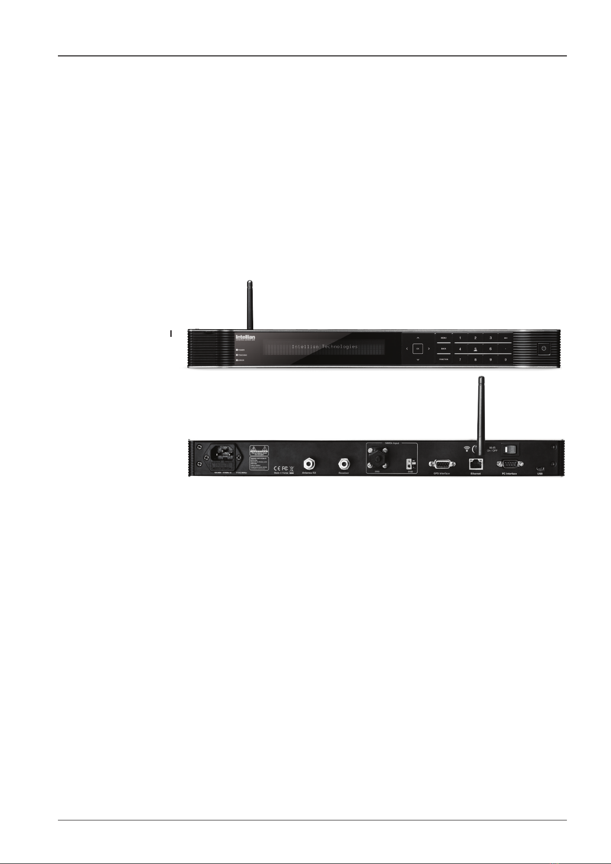
Antenna Control Unit (ACU)
The Antenna Control Unit (ACU) provides power to the antenna and controls
various settings of the antenna. Additionally, VFD (Vacuum Fluorescent Display)
allows for you to operate the ACU in the dark.
Front panel
Rear panel

t110W/t130W/t110Q/t130Q – Marine Satellite Television System
16
The functions of the ACU are as follows :
• System startup
• Change of target satellite
• Monitoring current status
• Setting antenna manual search
• Setting antenna set skew
• Setting antenna search parameter
• Setting antenna set parameters
• Executing antenna diagnosis
• Setting the satellite pair
• Edit satellite information
• Setting the region
• Finding transponders
• Setting the GPS and Gyrocompass
• System backup & restore
• Copy log and rmware upgrade through USB
• Supports Wi-Fi ACU operation
• Built-in web-based remote control management
• Front panel Management Ethernet port
• Installation settings
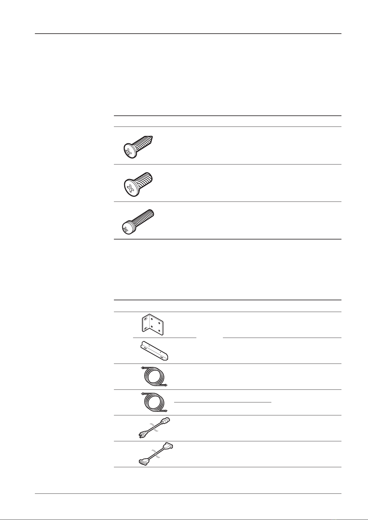
Installation Kit
Contains the items required for mounting the antenna unit and ACU to your vessel.
Antenna Q’ty Description Size Remark
5Hex. Bolt M12 x 80L
Antenna-Deck
5Flat Washer M12
5Spring Washer M12
10 Hex. Nut M12
17
INSTALLING THE ANTENNA
Item Image Q’ty Description Size Remark
1
2
ACU
Bracket
Rack - ACU-19inch Rack
2 Table - ACU-Table
2 1 RG6 Cable
(Optional) 30m ACU to ANT
3
1 RG6 Cable 15m
ACU to Receiver
1 RG6 Cable 3m
4 1 AC Power Cord
(CEE7/7) 1.5m ACU Power
5 1 PC Serial Cable 1.8m ACU to PC
ACU Q’ty Description Size Remark
5Self-Tapping
Screw 4 x 16 Table Mount
Bracket
10 Flat Head Screw M4 x 12L Rack Mount
Bracket ACU
5Sems Bolt M3 x 12L Table Mount
Bracket ACU
Other Components

t110W/t130W/t110Q/t130Q – Marine Satellite Television System
18
Item Image Q’ty Description Size Remark
6 1 USB Cable
(A-A) 1.8m ACU to PC
7 2 Rubber Gland RG6 Antenna Cables
8 5 Hex Socket
Head Cap M6 x 40L Radome (Top-Bottom)
9 5 Spring Washer M6 Radome
(Top-Bottom)
10 5 Flat Washer M6 Radome
(Top-Bottom)
11 1 WiFi Antenna 110mm -
12 1 User Manual - -
13 1 Mounting
Template - -
14 1 USB Flash Drive - -
19
INSTALLING THE ANTENNA
Planning the Installation
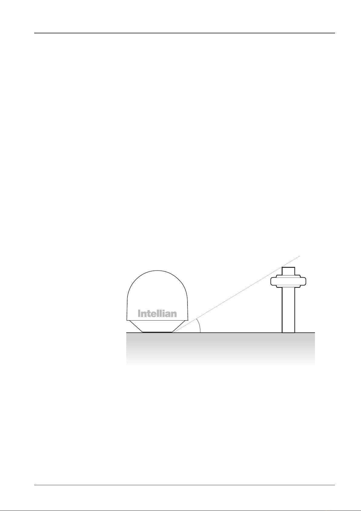
Selection of Antenna Installation Site
Install the antenna in accordance with the following procedures to ensure maximum
performance of the antenna. The ideal antenna site should have a clear view of
the horizon or satellite all around it. Please be sure there are no obstacles within
15º above the center of the antenna. Any obstacles can prevent the antenna from
transmitting and receiving the satellite signal.
Do not install the antenna near by the radar especially on the same plane as the
microwave radar transmissions as these will overload the antenna front-end circuits.
It is recommended to position the antenna at least 4 feet (1.2m) above or below the
level of the radar and minimum of 15 feet (4.6m) away from any high power short
wave radars.
The mounting platform should be robust enough and not subject to excessive
vibration. The movement of the antenna can be minimized by installing at the center
of the vessel. For optimal performance of the antenna, it is not recommended to
install on any corner of the vessel, where the movement of the vessel is the greatest.
Install the bottom of the antenna parallel to the surface of the sea and x tightly to
the structure of the vessel.
15°
Antenna Unit Obstacle

t110W/t130W/t110Q/t130Q – Marine Satellite Television System
20
System Cables
Before installing the system cables, you need to take the following points into
consideration.
• All cables need to be well clamped and protected from physical damage
and exposure to heat and humidity.
• A cable with an acute bend is should be avoid.
• Wherever a cable passes through an exposed bulkhead or deck head,
a watertight gland or swan neck tube should be used.
RF Cables (Customer Supplied)
Due to signal losses across the length of the RF coax on L-Band, Intellian recommends
the following 75 ohm coax cable types for standard system installations. For cables
that run longer than 100 meters, please consult Intellian Technologies.
Run Length Coaxial Cable Type
Up to 35 meters RG-6 or LMR-300-75
Up to 60 meters RG-11 or LMR-400-75
Up to 100 meters LMR-600-75
Power Requirements
Intellian t110W/t130W/t110Q/t130Q has been designed to work on a vessel’s power
supply rated at 110-220 V AC.
Type Multi-conductor, Shielded
Number of wires 2 conductors for NMEA 0183,
5 conductors for NMEA 2000
Gyrocompass / GPS Interface Cable (Customer supplied)
This manual suits for next models
3
Table of contents
Other Intellian Satellite TV System manuals


