Intelligent Lighting Controls, Inc. LightLEEDer User manual

Includes product details, installation, and wiring
information for the LightLEEDer EVO Integrated Relay
Panel
www.ilc-usa.com
EVO-INT Relay Panel
Operations Manual
ilc-usa.com | 952.829.19 00
intelligent
lighting controls

ilc-u sa.c om | 952 .829.19 00
intelligent
lighting controls
OPERATION MANUAL
Version 1A
6/11/2021
Class A FCC Device Statement (PENDING)
Warning: Changes or modifications to this unit not expressly approved
by the party responsible for compliance could void the user’s authority
to operate this equipment.
ote: This equipment has been tested and found to comply with the lim-
its for a Class A digital device, pursuant to Part 15 of the CC Rules. These
limits are designed to provide reasonable protection against harmful in-
terference when the equipment is operated in a commercial environ-
ment. This equipment generates, uses, and can radiate radio frequency
energy and, if not installed and used in accordance with the instructions,
may cause harmful interference to radio communications. Operation of
this equipment in residential area is likely to cause harmful interference
in which case the user will be required to correct the interference at his
own expense.
Includes product details, installation, and wiring
information for the LightLEEDer EVO Integrated Relay
Panel

ilc-u sa.c om | 952 .829.19 00
intelligent
lighting controls
Introduction
Thank you for purchasing the ILC LightLEEDer EVO Integrated Relay Panel. The LightLEEDer line is a
very flexible and quality product to meet all of your lighting control needs. These panels are
microprocessor-based programmable lighting controllers with networking capabilities. You can
program each of the controller’s inputs or data line devices to control any or all of the relay outputs.
Individual controllers may be linked together to form a local area network or linked across the
Internet to form a wide area network and function as a single interface. The LightLEEDer controllers
are UL and CC approved for commercial applications.
This operation manual is designed to assist you in understanding, installing, and programming
the product to fit your facilities’ requirements. This manual will give you step by step procedures to
assist you in a quick and proper installation. ILC is committed to help the installation go smoothly
with documentation and videos on our web site, quick installation guides, quick programming
guides, and technical telephone assistance through our toll free number.
Web site: www.ilc-usa.com
Phone Number: 952.829.1900

3
TABLEOFCONTENTS
Section1:LightingControllerDetails....................................................................................................5
1.0Enclosure.............................................................................................................................................5
1.1ControllerBoard..................................................................................................................................5
1.2OutputBoard......................................................................................................................................6
1.3LightLEEDerNetwork..........................................................................................................................7
Section2:Installation..........................................................................................................................8
2.0Pre‐InstallationChecklist....................................................................................................................8
2.1MountingtheEnclosure......................................................................................................................8
2.1.1Location........................................................................................................................................8
2.1.2EnvironmentalConsiderations.....................................................................................................8
2.1.3Mounting......................................................................................................................................8
2.2WiringtheEVO‐INT.............................................................................................................................8
2.2.1LineandLoadWires.....................................................................................................................8
2.2.2HardwiredInputs.........................................................................................................................9
2.3NetworkCableInstallation................................................................................................................10
2.3.1CableInstallationGuidelines.....................................................................................................10
2.3.2DataLineCable..........................................................................................................................11
2.3.3CableInstallation.......................................................................................................................11
2.3.4CableDistances..........................................................................................................................11
2.3.5CableTerminationandTesting..................................................................................................12
2.3.6ConnectCable............................................................................................................................13
2.4Pre‐Power‐UpChecklist....................................................................................................................13
2.5Power‐UpandCheckOut..................................................................................................................13
2.5.1Power‐Up...................................................................................................................................13
2.5.2VerifyRelayOperation...............................................................................................................13
2.5.3ClearingMemory........................................................................................................................13
2.5.4SettheInternalClock.................................................................................................................14
Section3:Programming.....................................................................................................................14
3.0Overview...........................................................................................................................................14

4
Section4:Appendix...........................................................................................................................14
AppendixA:LightLEEDerEVO‐4X/8X......................................................................................................14
AppendixB:ILCPhotoSensorHead.......................................................................................................15
AppendixC:NetworkedRelayPanels.....................................................................................................15

5
Section1:LightLEEDerEVOIntegratedPanelDetails
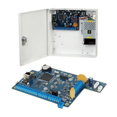
Figure1.1–ILCLightLEEDerEVOIntegratedRelayPanel
1.0Enclosure
TheenclosureisNEMA1ratedandisprovidedwithascrewcoverdoorforsurfacemounting.Allpanels
aresuppliedwith4pre‐drilledholesforeasymountingontothewall.Enclosurescomeinonesizeof10”
x10”x3”toaccommodate4to8integratedrelays.EnclosuresareconfiguredwithbothClass2andhigh
voltagesidesforeasyandseparatedroutingofwires.IncludedisahighvoltagebarriertoseparateClass
1andClass2wiring.
1.1ControllerBoard
Thecontrollerboardprovidestheintelligencetocontrolrelays,monitorinputs,andtocommunicatein
variousways.Theintegratedcomponentsinclude:
Powersupplyusedtoconverttheswitchersupply24VACintoDCvoltagesusedbythecontroller
andphotocell.
RelaystatusLEDsdrivenbycontroller.
Fourhardwiredinputswith24VDCforswitches,occupancysensor,ornursecallstation.Accepts
momentary,momentarypushbutton,ormaintainedswitchtypes.

6
LocalLightSyncdatalineportfordirectconnectionofupto17remotedevices.
RJ45PhotocellportforCAT‐5connectiontoILCPhotoSensorHead.
Real‐Timeclockprovidesalltime‐controlledfunctionsincludingtimeofday,dayofweek,day,and
daylight‐savingtime.Itwillkeepthetimeforatleast45dayswithoutpowertotheCPU.
Non‐volatilememoryforstoringprogramminginformation.Retainsdataforupto200yearswithout
anypowertotheCPU.
DatalinecommunicationsthroughRJ45forcommunicatingwithotherpanelsandLightSyncdata
linedevices.
Relayoverrideswitches“AllOn”or“AllOff”foroperationofrelays.
Figure1.2–LLEVOIntegratedControllerBoard
1.2OutputBoard
Theoutputboardincludestherelays,powersupply,andterminalsforwiringconnections.The
integratedcomponentsinclude:
Switchingpowersupplytoconvert120/277VAClinevoltagetolowvoltagesusedbythecontroller
board.
Screwdownterminalsforline,load,neutral,and0‐10Vdimmingconnections.
On‐boardrelayspopulatedineither4or8relayconfigurations.Eachsetof4relaysispoweredbya
singlelinevoltage16Acircuit.

7
Figure1.3–LLEVOIntegratedRelayOutputBoard
1.3LightLEEDerNetwork
PanelsandLightSyncdevicescanbelinkedtogetherwithstandardCAT‐5cableusingRJ45
connectorsthateasilyplugintothecontrollersanddevices.
Withtheuseofanetworkcontrolleryouareabletolinktogetherupto254panelsonthenetwork.

8
Section2:Installation
2.0 Pre‐InstallationChecklist
☐Unpackthelightingcontrolpanel.
☐Reportanydamagetothefreightcarrier.
☐Removetheenclosurecoverandsetaside.
☐Determineappropriatemountinglocationforpanel.
☐Mountthepaneltothewall.
☐Punchadditionalknockoutholesforhighandlowvoltageconduitrunsasrequired
☐Pulltheline,neutral,andgroundwiresfromcircuitbreakerboxtothepanelandterminate.
☐Pullloadwiresfromlightingloadstopanelandterminate.
☐PullCAT5datalinewirestopanelsanddevicesandterminatewithRJ45connectors.
☐Testallcableswiththeappropriatecabletester.
☐Pullalllowvoltageinputwiresandterminatetotheappropriateconnectors.
☐Cleanthecabinetofanyconstructiondebrisanddust.
☐Doublecheckallhighvoltageconnections.
☐Applypowertothepanel.
2.1MountingtheEnclosure
2.1.1Location
Determinetheproperlocationformountingthelightingcontroller.Typically,thepanelsaremounted
nearthelightingloadstobecontrolled.
2.1.2EnvironmentalConsiderations
TheEVOIntegratedRelayPanelisinstalledinaNEMA1enclosuredesignedforindoorapplications.The
panelshouldbemountedinanareawithanambienttemperaturebetween0and50°C(32°‐122°F),
humidityfrom10to90%non‐condensing,non‐explosive/corrosiveatmosphere,andstationary.
2.1.3Mounting
Theenclosureisprovidedwith4holeslocatedateachcorneroftheenclosure.Securetheenclosureto
themountingsurfacewiththeappropriatehardwarefortheapplication.
2.2WiringtheEVO‐INT
2.2.1LineandLoadWires
Pulla16A120VACor277VACcircuittotheLine1(L1)terminalforpoweringthefirstfourrelays(LD1‐4)
andcontrollerboard.Anadditional120VACor277VACcircuitcanbeterminatedatLine2(L2)foran
additional16Acapacityonthesecondset(LD5‐8)ofrelays.Pullallwiresfromlightingloadstothe
enclosure.Connecteachloadanditsdimmingwirestotheappropriateterminalontherelayoutput
board.Captheunusedleadtopreventelectricalshock.SeeFigure2.1below.

9
Figure2.1–EVOIntegratedOutputWiring
2.2.2HardwiredInputs
Pullthewiresfromswitches,occupancysensors,ornursecallstationsfromtheirrespectivelocationsto
theenclosure.BesuretoisolatetheClass2wiringfromthehighvoltagewiringasshowninthediagram
below.

10
Figure2.2–Class2andHVwiringareas
2.3 NetworkCableInstallation
2.3.1CableInstallationGuidelines
ObserveallILCDataCableRequirementsandLightSyncCableRunDistanceRequirementsasthey
pertaintoyourprojectinlayingoutthecableruns.
Maintainthetwistsofthepairsallthewaytothepointoftermination,ornomorethan1”
untwisted.
Makegradualbendsofthecable,wherenecessary.Nosharperthana1”radius
Dressthecablesneatlywithcableties.Uselowtomoderatepressure.
Uselowtomoderateforcewhenpullingcable.
Usecablepullinglubricantforcablerunsthatmayotherwiserequiregreatforcetoinstall.
DonotpullANYdatacableorswitchwireswithoralonganyhighvoltagewires.
KeepalllowvoltagetotallyseparatefromALLhighvoltage.FailuretodosowillvoidtheILC
warranty.

11
Keepcables2’‐3’awayfromanypotentialsourcesofEMIaspossible.(Linevoltageruns,
transformers,lightfixtures,etc.)
Installpropercablesupports,spacednomorethan5feetapart.
Alwayslabeleveryterminationpoint.Useauniquenumberforeachcablesegment.Thiswillmake
moves,adds,changesandtroubleshootingassimpleaspossible.Documenttheseontotheriser
provided.
AlwaystesteveryinstalledsegmentwithaCAT‐5cabletester.
Alwaysleaveextraslackinthecablerun,neatlycoiledupintheceilingornearestconcealedplace.
Alwaysusegrommetstoprotectthecablewhenpassingthroughmetalstudsoranythingthatcan
possiblycausedamage.
Alwaysfollowalllocalandnationalbuildingandfirecodes.Besureto“firestop”allcablesthat
penetrateafirewall.Useplenumratedcablewhereitismandated.
AlwayscontactILConinstallationsbetweenbuildingsorcablepulledunderground.Special
considerationsmaybeneeded.
2.3.2DataLineCable
ThedatalinecablesrequiredforcommunicationsbetweenpanelsanddevicesusesstandardCategory5.
RJ45connectorsmustberatedforthetypeofcablebeingterminatedto.Besurethatcablerunina
plenumisratedforthatuse.Anycablerunundergroundmusthaveundergroundratedcable,havea
12AWGsolidCuwirepulledalongwithitgroundedatoneend,andhavesurgesuppressorsinstalled.
ContactILCforjobspecificquestions.
2.3.3CableInstallation
DatalinecablesneedtointerconnectallthelightingcontrolpanelsandallLightSyncdatalinedevices.
EachcontrollerhasalocalportthatconnectsLightSyncdevicesonly.Thecontrolleralsoincludes“in”
and“out”portsforconnectingpanelstogether,whichcanalsoconnectLightSyncdevices,butitis
suggestedthattheyareconnectedtothelocalport.Note:AnetworkcontrollerisrequiredifusingData
IN/OUTports.DatacabletoeitherpanelsorLightSyncdevicesareruninadaisychainpatterntoforma
network.“T”connectionsarepermittedwiththeuseofaPowerSupplyRepeater(PSR)andhome‐run
LightSyncdevicesmaybedonewithaLightSyncHub.
2.3.4CableDistances
Dataandpoweriscarriedacrossthenetworkcable.Therearelimitationshowfardatacanberun,how
manydevicesareontheline,andhowmuchpowerisontheline.SeeFigure2.3fordetails.Withthe
additionofaPowerSupplyRepeaterorPowerSupplyRepeater6dataandpowercanberenewed.
Besuretorecordallcabledistancesontheriserprovided.

12
Figure2.3–NetworkCableRunDistanceDetail
2.3.5CableTerminationandTesting
DatacableswillberequiredtobeterminatedwiththeproperRJ45crimp‐onconnectorsforthecable
beingused.Followthepin‐outshowninFigure2.4.Besurethecolor‐codedwiresareterminated
exactlyasshown.Alwaysvisuallyinspectforacompletelyseatedcrimp,asdamagecouldoccurtothe
matingconnectorontheprocessorordevice.

13
Figure2.4–RJ45CableTerminationDetail
Testeverycablepriortoinstallationforshorts,opens,andinductedvoltage.Besurenottoconnectyour
testertoacableconnectedtoanyhardwareasdamagemayoccur.
2.3.6ConnectCable
Aftercablesaretested,theycanbepluggedintothepanelsanddevices.Cablesstartatthe“Out”port,
gotothenextpanelordeviceandentersthe“In”port.Thisiscontinueduntilalldevicesareconnected.
2.4 Pre‐Power‐UpChecklist
☐Verifyallribboncablesbetweencontroller/outputboardsarewellseated.
☐Verifyallhighvoltagewiresareterminatedandthehighvoltagebarriersisinstalled.
☐Verifyalldatacables,sensorwires,dimmingwires,inputwiresareterminatedproperly.
2.5Power‐UpandCheckOut
2.5.1Power‐Up
ThecontrollerwillturnononcetheLine1andNeutralwiresareterminatedandthecircuitisenergized.
ThepowerLEDlocatedinthelowerleftshouldlightup.
2.5.2VerifyRelayOperation
Withthecontrollerpowereduppressthe“ALLON”pushbuttonswitchlocatedonthelowerleftsideof
thecontroller;alltherelaysshouldturnON.Pressthe“ALLOFF”buttonandverifythatallrelaysturned
OFF.Therelayshaveanon‐boardLEDthatindicatestheirstate.
2.5.3ClearingMemory
Itisverycriticaltoclearthememoryinthecontrollerpriortoprogrammingtoeliminateanypossible
unwantedmapping.IntheILCLightLEEDerSoftware,connecttothepanelwithadiagnostictoolonthe
networkport.Onceconnectednavigatetothevirtualkeypadonthe“Connect”screen.Fromthe
keypad/displaypush“Edit”,thenscrolldownto“SpecialFunctions”,thenscrolldownto“FirmwareRe‐
vision”,pressbothupanddownscrollbuttonssimultaneouslytoenterahiddenmenu,andthenscroll
downto“ClearAllMemory”.

14
2.5.4SettheInternalClock
Clocksettingsmustbesetinthecontrollerifthepanelrunstimeschedulesorturnson/offlightsin
referencetosunrise/sunset.IntheILCLightLEEDerSoftware,connecttothepanelwithadiagnostictool
onthenetworkport.Onceconnectednavigatetothevirtualkeypadonthe“Connect”screen.Fromthe
keypad/displaypush“Edit”andscrolldowntothe“Clock”menu.Fromthispartofthemenu,youcan
setthetimeanddate,setupthedaylight‐savingtimesettings,settheastronomicalparameters,and
viewthecurrentsunrise/sunsetsettings.SeeSection3formoredetails.
Section3:Programming
3.0Overview
TheLightLEEDerProSinglePanel&LightLEEDerNetworkConfigurationSoftwareareILCpriority
softwarepackagesdesignedfortheILCLightLEEDerserieslightingcontrolpanels.TheLLProSingle
panelcanbeutilizedonsinglepanels,whiletheLLProNetworkConfigurationSoftwarerequiresan
NetworkControllerinthesystem.
Note:ForprogramminginformationandsoftwareinstallationseeLightLEEDerProSoftwareManual.
Section4:Appendix
AppendixA:LightSyncEVO‐4X/8X
Inadditiontotheon‐boardrelaysprovidedwiththeLightLEEDerEVOIntegratedRelayPanel,additional
relayscanbeaddedwiththeLightSyncEVO‐4X/8XPanel.TheLSEVO‐Xisavailablein4or8relay
configurationsandexpandsanyLightLEEDercontrollertooperateadditionalrelays.Connectthe“Local”
portoftheLLEVO‐INTControllertothe“In”portofyourfirst4X/8Xboard,andthe“Out”porttoeach
subsequentLightSyncdevice.TheLLEVO‐INTcanoperateupto20totalrelays,includingtheon‐board
relays.RefertoFigure4.1forLSEVO‐04X,8Xaddressswitchsettings.
Figure4.1–LSEVO‐4X/8XAddressSwitchSettings

15
AppendixB:ILCPhotoSensorHead
TheLightLEEDerEVOIntegratedRelayPanelhasaRJ45portforconnectiontoasinglePhotoSensor
Head.RunaCAT‐5cablefromthePhotocellportofthecontrollertothedesiredlocationofthephoto
sensor.TerminatetheCAT‐5cablepairsasshownbelowinFigure4.2.
Figure4.2–ILCPhotoSensorTermination
AppendixC:NetworkedRelayPanels
LightLEEDerNetworkControllershavethecapabilitytocontrolupto255LightLEEderpanelsincluding
theLightLEEDerEVOIntegratedRelayPanel.TheremoteEVO‐INTpanelsareconnectedtothenetwork
CAT‐5“Out”portfromtheLLNCandaddressedasoneofthe255LightLEEDerpanelsinthesame
mannerasallotherLightLEEDerpanels.AllstandardLightLEEDernetworkingoperationsaresupported
withtheLLEVO‐INT.

For more information, please contact:
ilc-u sa.c om | 952 .829.19 00
intelligent
lighting controls
Table of contents

