Fenwal 1019-E User manual

Revisione 2 Pagina 1 di 46 TM0009-A
1019-E
ALARMS MANAGEMENT
MULTIFUNCTIONAL
CONTROL PANEL
OPERATOR MANUAL
MANUAL NO.TM0009-A

Page 2 of 46
PROPRIETARY RIGHTS NOTICE
This document and the informations that it contains are the propety of
FENWAL ITALIA S.p.A.. Rights to duplicate or otherwise copy this
document, the rights to disclose the document and the informations that it
contains to others and the right to use the information contained therein may be
acquired only by written permission signed by a duly authorised officer of
FENWAL ITALIA S.p.A..
The informations contained in this document may be changed without notice.
Duplication is not allowed - FENWAL Italia S.p.A.

Page 3 of 46
Preliminary Pages
AMENDMENT INCORPORATION RECORD
Amendment No.
Brief Description of Content
Author
1
Production configuration.
Level 2 fire Password = 144567
Level 3 fire Password = 198767
2
3
Production Configuration.
Servicing Password = 3*****
4
5
6
7
8
9
10
INDEX

Page 4 of 46
____
1SAFETY SECTION (FIRE) ........................................................................................................................... 5
1.1 INTRODUCTION ................................................................................................................................6
1.2 ACCESS TO THE PANEL FUNCTIONS........................................................................................ 11
1.2.1 Silence Buzzer ............................................................................................................................. 13
1.2.2 Scroll ............................................................................................................................................ 13
1.2.3 Silence Sounders ......................................................................................................................... 13
1.2.4 Reset............................................................................................................................................. 14
1.2.5 Delay Override ............................................................................................................................ 14
1.2.6 Evacuate ...................................................................................................................................... 14
1.2.6 Confirmation button (↵
↵↵
↵)............................................................................................................ 15
1.2.7 Cancel button (←
←←
←)....................................................................................................................... 15
1.2.8 Numerical buttons (0-9)............................................................................................................. 15
1.2.9 Directional buttons (arrows)..................................................................................................... 15
1.3 ISOLATE/DEISOLATE .................................................................................................................... 16
1.3.1 Inputs zones ................................................................................................................................16
1.3.2 Output zone ................................................................................................................................. 17
1.3.3 Devices ......................................................................................................................................... 18
1.3.4 Panel Sounders............................................................................................................................ 19
1.3.5 Local Buzzer................................................................................................................................20
1.4 LIST ..................................................................................................................................................... 21
1.4.1 Zones ............................................................................................................................................ 21
1.4.2 Isolations...................................................................................................................................... 22
1.4.2.1 Devices (Zones list/Isolate devices).......................................................................................... 22
1.4.2.2 Panel Function (system isolation list) ....................................................................................... 23
1.4.3 Event Log..................................................................................................................................... 23
1.4.4 Alarm Log.................................................................................................................................... 24
1.5 MANAGEMENT ................................................................................................................................24
1.5.1 Extinction Enable........................................................................................................................ 25
1.5.2 Time and Date ............................................................................................................................. 25
1.5.3 Panel Configuration.................................................................................................................... 26
1.5.3.1 Standard Options....................................................................................................................... 26
1.5.3.2 Communications ....................................................................................................................... 27
1.5.3.3 Various Parameters ................................................................................................................... 31
1.5.4 User Passwords ........................................................................................................................... 31
1.6 TEST .................................................................................................................................................... 33
1.6.1 Panel Test .................................................................................................................................... 33
1.6.2 Zone Test ..................................................................................................................................... 33
1.7 EVENTS VISUALIZATION ............................................................................................................. 35
1.7.1 Initialising.................................................................................................................................... 35
1.7.2 Isolate ........................................................................................................................................... 37
1.7.3 Fault ............................................................................................................................................. 38
1.7.4 Prealarm ...................................................................................................................................... 41
1.7.5 Alarm ........................................................................................................................................... 43

Page 5 of 46
1 SAFETY SECTION (FIRE)

Page 6 of 46
1.1 INTRODUCTION
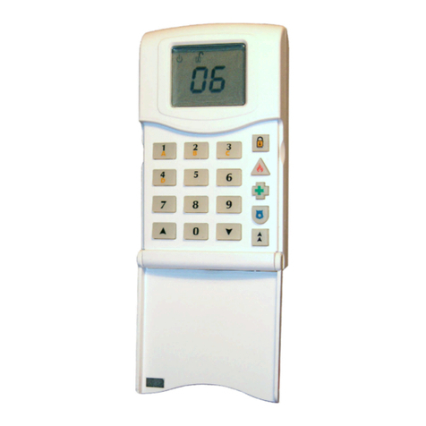
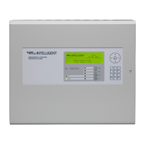
The operator interface of the new 1019-E panel is a 256x64 Dots graphic LCD, with 14
signals leds and 22 functions buttons as shown in figure A.
The 1019-E is built in accordance to the EN-54-2 std.with the following functions:
Function EN54-2 Ref. Paragraph
Single Fault Indication 8.3
Delayed Outputs 7.11
Addressable devices out of service 9.5
Test condition 10
Outputs to Fire Alerting Devices 7.8
Outputs to Fire Protection Devices 7.10
L1 Led Alarm (fire)
The led flashes when it recives an alarm status from a Zone 1 device of the personalization.
It becames a fixed light after the acknowledge control of the operator, or from the host
computer.
It returns a flashing light in case it receives another alarm status signal.
It switches off after the reset control of the operator, or from the host computer, or when it
receives the exclusion control of that device.
L2 Led Prealarm (fire)
The led flashes when it recives a prealarm status from a Zone 1 device of the personalization.
It becames a fixed light after the acknowledge control of the operator, or from the host
computer.
It returns a flashing light in case it receives another prealarm status signal.
It switches off after the reset control of the operator, or from the host computer, or when it
receives the exclusion control of that device.
FENWAL

Page 7 of 46
L3 Led Test (Fire)
It is illuminates constantly when the panel is in test mode.
It switches of automatically at the test mode exit.
In case of a zone test mode, the alarm signal from devices/inputs must not start the actuation,
but only the signals.
The devices must automatically reset after 10 seconds.
L4 Led Power-On (fire/intrusion)
It is illuminates constantly when power supply is turned on.
The led is extinguished when power supply is turned off.
L5 Led Common Fault (fire)
It is a cumulative signal for all faults possibilities.
The led will flash following the L6-L7-L8-L13-L14 activations.
The led will extinguish when the fault problem disappear.
L6 Led Device Fault (fire)
The led flashes when it receives a fault status from a detector/input/actuator that is not part of
sounders group of Zone 1 of personalization.
The led extinguishes after the reset control of the operator or from the host computer or when
it receives the exclusion control of that detector/input/actuator.
L7 Led Sounder Fault (fire)
The led flashes when it receives a fault signal from a indoor or outdoor emergency exit.
The led extinguishes after a reset control of the operator or from host computer or when it
receives the exclusion control of that actuator.
L8 Led P.S.U. Fault (fire/intrusion)
The led will flash after receiving a power supply generic fault signal.
The led will extinguish automatically when the fault problem disappear.
L9 Led Common Isolate (fire)
The led illuminates constantly in presence of any device exclusion, in Zone 1 of
personalization, linked with L10 – L11 activation.
The led extinguishes automatically when the above menthioned exclusion disappear.
L10 Led Device Isolate (fire)
The led illuminates constantly when any type of devices/inputs exclusion in Zone 1 of
personalization is present.
The led extinguishes automatically when the above menthioned exclusion is not present.
L11 Led Output Isolate (fire)
The led illuminates constantly when any type of actuators exclusion in Zone 1 of
personalization is present.
The led extinguishes automatically when the above menthioned exclusion is not present.
L12 Led Output delayed (fire)
The led is flashing during the count down delay of the Zone 1 actuator.

Page 8 of 46
The led is extinguished automatically at the end of the count down or when the delay override
button is pressed
L13 Led System Fault (fire/intrusion)
The led is illuminated constantly when a microprocessor fault (watch-dog) or a memory fault
is detected.
The led is extinguished automatically only when power supply is turned off
The led is installed on the card in a visible location.
L14 Led Earth Fault (fire/intrusion)
The led flashes when a power supply earth leakage is detected.
The led extinguishes automatically when the fault problem disappear.
The led is installed on the card in a visible location.
T1 Silence Buzzer Button (Fire)
It affects at access level 1 or upper and induces the disactivation of the panel buzzer only for
the fire functions.
An acknowledge message must be visualizzed on the display, memorized in the event log and
sended to the periferical (if any - host/printer i.e.).
T2 Reset button (Fire)
It affects at access level 2 or upper and induces the reset of the zone 1 panel alarms or fault
conditions, presents in that moment.
A reset message must be visualizzed on the display, memorized in the event log and sended
to the periferical (if any - host/printer i.e.).
This function can be activated only after the acknowledge of the buzzer (T1 button) and
sounders (T4 button).
T3 Scroll button (Fire)
It affects at access level 1 or upper and induces the chronological scroll of the alarms or faults
presents in that moment for the selected zone. The details of each individual event are
visualized.
The events reported are referred tothe fire fighting zone 1.
T4 Silence Sounders button (Fire)
It affects at access level 2 or upper and induces the disactivations of the 4 default sounders
checked outputs and all outputs personalized as sounders outputs.
An acknowledge message must be visualized on display, memorized in the event log and
sended to the peripherical (if any - host/printer i.e.). This function can be activated only after
the acknowledge of the buzzer (T1 button).
T5 Delay Override button (Fire)
It affects at access level 1 or upper and induces the cancellation of the actuators activation
delay for the zone 1 of the personalization, for which the count down delayis in progress.
T6 Evacuate button (Fire)
It affects at access level 2 or upper and induces the immediate activation of the 4 default
sounders checked outputs and all outputs personalized as sounders outputs.

Page 9 of 46
A message must be visualized on display, memorized in the event log and sended to the
pheripherical (if any – host/printer i.e.).
T7 Numerical button 1 (Fire/intrusion)
It is utilized to select the password numerals and to introduce datas in the various operator
menu .
T8 Numerical button 2 (Fire/intrusion)
It is utilized to select the password numerals and to introduce datas in the various operator
menu .
T9 Numerical button 3 (Fire/intrusion)
It is utilized to select the password numerals and to introduce datas in the various operator
menu .
T10 Numerical button 4 (Fire/intrusion)
It is utilized to select the password numerals and to introduce datas in the various operator
menu .
T11 Numerical button 5 (Fire/intrusion)
It is utilized to select the password numerals and to introduce datas in the various operator
menu .
T12 ESC button (Fire/intrusion)
It affects in the various operator menu to cancell the pressed buttons or selected menu shown
on display. Induces the return tothe previous menu.
T13 Numerical button 6 (Fire/intrusion)
It is utilized to select the password numerals and to introduce datas in the various operator
menu .
T14 Numerical button 7 (Fire/intrusion)
It is utilized to select the password numerals and to introduce datas in the various operator
menu .
T15 Numerical button 8 (Fire/intrusion)
It is utilized to select the password numerals and to introduce datas in the various operator
menu .
T16 Numerical button 9 (Fire/intrusion)
It is utilized to select the password numerals and to introduce datas in the various operator
menu .
T17 Numerical button 0 (Fire/intrusion)
It is utilized to select the password numerals and to introduce datas in the various operator
menu .

Page 10 of 46
T18 CR button (Fire/intrusion)
It affects in the various operator menu to confirm the pressed buttons or to confirmthe
selected menu on display.
T19 Arrow up button (Fire/intrusion)
It is utilized to select the menu various options in vertical way..
T20 Arrow down button (Fire/intrusion)
It is utilized to select the menu various options in vertical way..
T21 Arrow right button (Fire/intrusion)
It is utilized to select the menu various options in horizontal way.
T22 Arrow left button (Fire/intrusion)
It is utilized to select the menu various options in horizontal way.

Page 11 of 46
1.2 ACCESS TO THE PANEL FUNCTIONS
The access to the panel fire fighting functions is organized on 3 different levels. The access to
the first level does not require any password. Each access level has a proper operative system,
as shown in the following table, that define the operator use of the panel.
It is possible reach the 2 and 3 levels only digitinga password on the front keyboard of the
panel.
Performances
Options
Access
Level 1
Access
Level 2
Access
Level 3
Panel Controls
Panel acknowledge
Event Visualizator
Sounders Acknowledge
Reset
Output Delay Cancellation
Evacuate
Confirmation Button (↵)
Cancel Button (←)
Numeric. Button (0 to 9)
Directional Button
--
--
--
Isolate Menu
Zones (Devices/Inputs)
Zones (Actuators)
Devices
Panel Sounders
Panel Buzzer
--
--
--
--
--
List Menu
Zones List
Isolation List
Event log
Alarm log
--
--
--
--
Management
Menu
Extinction Enable
Time and Date
Panel Configurations
Users Password
--
--
--
--
--
--
Test Menu
Panel
Zones Test
Keyboard Test
Diagnostic
--
--
--
--
--
--
--
--
--
At the end of the start sequence, in stand-by conditions, green led (L4) “Power On” must be

Page 12 of 46
illuminated and, at the same time, the panel display showes the figure 1 message.
STATU S
NORM AL
Access Level 1
Tue 03 Apr 01 10:33
FENWAL
figure 1
To reach the required level (level 2 or 3), press button 1, the request “Select password” will
be shown on display (see figure 2). At this time digit the four numbers of the password code
and press confirmation button. The selected numbers shall be shown on display with simbol
“#”.If the selected password is correct the functions of the level associated with the selected
password is reached.
STATU S
NORM AL
Access Level 1
Tue 03 Apr 01 10:33
Passw ord ####
figure 2
When the password is accepted, the display will show all the available options for that level,
as reported in figure 3.
Figure 3 shows the relevant controls that is possible select digiting the access level 3
password. The panel will exit automatically from the selected access level after one minute of
operator inactivity, or after an event.

Page 13 of 46
Safety (Area-1) A ccess Leve l3
1:Iso late/Deiso late
2:List
3:M anagem ent
4:Test
Selectoption using
▲ ▼ and
↵
figure 3
1.2.1 Silence Buzzer
When the panel inside buzzer is operating, pressing the keyboard Silence Buzzer button, the
buzzer will acknowledge. The display will show for few seconds in the lower right corner a
confirmation message of this operation, as described in figure 4.
Total 1
First Zone 1
Buzzersilenced
FA U LT
figure 4
1.2.2 Scroll
When the control panel shows more than one activation, pressing Sroll button all the panel
active function will be shown on display. Press the button one by one and all the selected
zone active functions will be shown. When the last active function is visualized, pressing the
scroll button the first active function will be shown again.
1.2.3 Silence Sounders
The frontal panel Silence Sounders button is operative only at levels 2 and 3, and when
pressed the display confirms the activation. The consequence of this button actuation is the
disactivation of all devices defined as sounders. The Panel Reset button shall be operative
only after the acknowledge of the alarms.

Page 14 of 46
1.2.4 Reset
The frontal panel Reset button is operative only at levels 2 and 3. The consequence of this
button actuation is the cancellation of the panel active conditions and the return to the normal
status.
1.2.5 Delay Override
The Delay Override button is operative at level 1. The consequence of thi button actuation is
the cancellation of all programmed delaies. When this button is pressed the display will
confirm the activation and the timer count downwill be cancelled.
1.2.6 Evacuate
The frontal panel Evacuate button actuation will activate all the sounders circuits and all the
sounders programmed outputs. When this button is pressed the display will show an operation
confirmation message as reported in figure 5.
EV A C U A TE Access Level 1
Tue 03 Apr 01 10:33
FENWAL
figure 5
The evacuate function will be active till the silence sounders button will be pressed. Pressing
Evacuate button when an alarm is active, the display will show the confirmation, as per figure
6, up to the deactivation.
Total 1
First Zone 1
ALARM
Press
↵ orESC to quit
M anualEvacua te
figure 6

Page 15 of 46
1.2.6 Confirmation button (↵
↵↵
↵)
With the Control Panel in “Normal Status”, the Confirmation button is used to accept
numerical codes,. to reach the menu options and to confirm system datas insertion. During an
alarm activation, Confirmation button will be used to show datas of each devices as per figure
7.
Total 1
First Zone 1
Sensors 01:SEN 1 01/01
ALARM
Press Scrollor ESC to quit
Figure 7
1.2.7 Cancel button (←
←←
←)
Pressing the Cancel button the selected menu option will be deselected or cancelled. Next
pression on this button will return the panel at level 1.
1.2.8 Numerical buttons (0-9)
The numerical buttons will be mainly used to insert the access level password as described in
section 1.2 “Access to the panel functions”. The numerical buttons can be used to select menu
options of each level and to introduce datas in the system.
1.2.9 Directional buttons (arrows)
The directional buttonsi, UP, DOWN, LEFT and RIGHTare used to select access level menu,
to visualized the actuations. The control panel display will give the instructions to use the
directional buttons.

Page 16 of 46
1.3 ISOLATE/DEISOLATE
Selecting Isolate/Deisolate it is possible to reach the isolate/deisolate menu as shown in figure
8. The menu option can be selected using the directional buttons and the confirmation button
to confirm the option choise.
Isolate/Deisolate A ccess Le vel3
1:Zone Inputs
2:Zone Outputs
3:Devices
4:PanelSounders
5:PanelBuzzer
Select option using
▲ ▼ and
↵
figure 8
1.3.1 Inputs zones
Selecting this options, with a single operation is possible to isolate all the inputs and the
devices of a zone. It is required to introduce the zone number as shown in figure 9.
Sensors/Inputs Zone A cce ss Le ve l3
Zone Num ber 001
Select zone num berand press
↵
Figure 9
Selecting the zone number the display will show the relevant status of the devices/inputs of
the first four zone, starting from the selected zone as per figure 10. In this phase is possible to
shift with the directional buttons and after the designed zone selection, isolate or deisolate the
zone inputs pressing confirmation button. If the option is isolate the “COMMON ISOLATE”
led will illuminate constantly and “DEVICE ISOLATE” led will flash. Press ESC button to
return to the previous menu.

Page 17 of 46
Sensors/Inputs Zone A cce ss Level3
1:Zone 001 Norm
2:Zone 002 Norm
3:Zone 003 Isol
4:Zone 004 Isol
▲ ▼ and
↵ orESC to quit
figure 10
1.3.2 Output zone
Selecting this option with a single operation, it is possible to isolate all the outpots of a zone.
It is required to introduce the zone number as shown in figure 11.
O utputs Zone A ccess Leve l3
Zone Num ber 001
Select zone num berand press
↵
figure 11
Selecting the zone number the display will show the relevant status of the actuators of the
first four zone, starting from the selected zone as per figure 12. In this phase is possible to
shift with the directional buttons and after the designed zone selection, isolate or deisolate the
zone outputs pressing confirmation button. If the option is isolate the “COMMON
ISOLATE” led will illuminate constantly and “OUTPUT ISOLATE” led will flash. Press
ESC button to return to the previous menu.
O utputs Zone A ccess Le ve l3
1:Zone 001 Norm
2:Zone 002 Norm
3:Zone 003 Isol
4:Zone 004 Isol
▲ ▼ and
↵ orESC to quit
figure 12

Page 18 of 46
1.3.3 Devices
Selecting this option is possible to isolate a single device either an imput, a detector, or an
output. It is required the zone number as shown in figure 11.
After selecting the zone number the display will show three available options as per figure 13.
Select the needed option by means of the directional buttons and press confirmation button
for the required option.
Devices AccessLe ve l3
1:Sensors
2:Inputs
3:Outputs
Select option using
▲ ▼ and
↵
figure 13
To isolate a single device of a zone, the display will require the insertion of the zone number,
by means of the numerical buttons and the confirmation button. At this point the display will
require the device number to insert with numerical and confirmation buttons as per figure 14.
Isolate Sensors A ccess Le ve l3
Zone Num ber 001
Sensor Num ber 01
Select zone and sen sor; confirm with ↵
figure 14
After the device selection by mean of the confirmation button, the first four devices list,
starting from the selected number will be shown. (See figure 15).

Page 19 of 46
Isolate Sensors A ccess Le ve l3
Zone 001
1:SEN S 1 Norm
2:SEN S 2 Norm
3:SEN S 3 Isol
4:SEN S 4 Isol
Select sensor using
▲ ▼ and
↵
figure 15
Pressing the Confirmation button is possible to isolate or deisolate the selected devices.
In the same manner, selecting from figure 13 menu the option inputs or actuators, will be
possible to operate from these devices in the same way as above described.
When a devices or an input is isolated the COMMON ISOLATE led will illuminate
constantly and DEVICE ISOLATE led will flash. When an output is isolated the COMMON
ISOLATE led will illuminate constantly and OUTPUT ISOLATE led will flash. Pressing
repeatedly the cancel button the display, throught all the options return at level 1 where
message ISOLATE DEVICE is shown as per figure 16.
DEVICES
ISO LATED
Access Level 1
Tue 03 Apr 01 10:33
FENWAL
figure 16
1.3.4 Panel Sounders
Selecting this option is possible to isolate the two local sounders output of the panel as shown
in figure 17. In this phase acting on directional buttons is possible to select the needed output,
than press confirmation button to isolate or deisolate the selected output sounder.

Page 20 of 46
Isolate PanelSounders A ccess Leve l3
1:Sounders O utput1:Norm al
2:Sounders O utput2:Isolated
▲ ▼ and
↵ or ESC to quit
figure 17
After the isolate control the COMMON ISOLATE led will illuminate constantly and
OUTPUT ISOLATE led will flash. Press ESC button to return to the previous menu.
1.3.5 Local Buzzer
Selecting this option is possible to isolate the panel local buzzer from 1 to 120 minutes as
shown in figure 18. Isolate the buzzer and then insert the time in minutes (120 minutes max.).
Isolate Buzzer A cce ss Leve l3
Loca lBuzzer Norm al
Isolated Time 001 minutes
Enter buzzerisolate time;confirm with ↵
figure 18
After isolate control the COMMON ISOLATE led will illuminate constantly and OUTPUT
ISOLATE led will flash. Press ESC button to return to the previous menu. Pressing
repeatedly cancel button, throught all the option menu return at level 1, where message
ISOLATE BUZZER is shown as per figure 19.
Table of contents
Other Fenwal Control Panel manuals
Popular Control Panel manuals by other brands
D+H
D+H CPS-M1-S Original instructions
EDM
EDM Solution 862 installation manual
GRD Systems
GRD Systems Asteria user manual
Zeta Alarm Systems
Zeta Alarm Systems Infinite 8 User manual, maintenance guide & log book

Kramer
Kramer K-NET RC-53D user manual
Fire-Lite Alarms
Fire-Lite Alarms MS-9200E Programming, installation, maintenance and operating instruction manual
