Intellijel Jellysquasher User manual

Jellysquasher Manual v1.00
Jellysquasher
Analog Compressor and Tone Shaper

JellysquasherManualv1.00
TableofContents
Table of Contents
Overview
Features
Installation
Before Your Start
Installing Your Module
Front Panel
Controls
Inputs and Outputs
Signal Flow Diagram
Technical Specifications
Page 1

JellysquasherManualv1.00
Overview
The Jellysquasher is an analog compressor and color module. It features a 100% analog signal
path and a sidechain feed-forward compressor. The output is routed through an Edcor
transformer with highly desirable saturation qualities. In addition to the compressor there are
three carefully-tuned analog circuits that impose additional character on the output:
● TUBE adds nonlinear distortion with second order harmonics
● TAPE adds symmetrical distortion with both even and odd harmonics
● XFORM modifies the transformer feedback circuit, giving a boost to low bass content
The three color circuits can be engaged in any combination.
The sidechain signal of the compressor can be routed through a voltage-controlled SVF with LP,
BP, and HP modes. A trimmer can be used to adjust the filter Q. The filter can also be used
independently from the rest of the module.
An external sidechain input allows the compressor to be triggered with an external source, and
wet/dry control allows blending of the uncompressed signal for "New York"-style parallel
compression.
Features
●100% analog signal path and sidechain feedforward compressor.
●Unique log based RMS detector.
●Output routed through a specially selected Edcor transformer with highly desirable
saturation qualities.
●Three carefully designed analog circuits to impose specific character on the output
signal.
●All three color circuits can be engaged in any combination to react differently based on
the input drive level and makeup gain
●Sidechain routed through a voltage controllable SVF filter with LP, BP and HP modes. A
trimmer on the PCB allows you to adjust Q. This filter can be used independently of the
rest of the module.
●External sidechain input allows triggering of the compressor with external sources.
●Link IN/OUT allows two Jellysquashers to be chained together for stereo operation.
●Full CV control of sidechain cutoff, threshold, ratio, attack time, release time, and
makeup gain.
●LED bargraph with selectable display modes to view the signal level in VU or the gain
reduction in dB.
Page 2

JellysquasherManualv1.00
Installation
Intellijel Eurorack modules are designed to be used with a Eurorack-compatible case and power
supply.
BeforeYourStart
Before installing a new module in your case you must ensure your case’s power supply has
sufficient available capacity to power the module:
● Sum up the specified +12V current draw for all modules, including the new one. Do the
same for the -12 V and +5V current draw. The current draw will be specified in the
manufacturer's technical specifications for each module.
● Compare each of the sums to specifications for your case’s power supply.
● Only proceed with installation if none of the values exceeds the power supply’s
specifications. Otherwise you must remove modules to free up capacity or upgrade your
power supply.
You will also need to ensure you have enough free space (hp) as well as free power headers in
your case to fit the new module.
You can use a tool like ModularGrid to assist in your planning. Failure to adequately power your
modules may result in damage to your modules or power supply. If you are unsure, please
contact us before proceeding.
InstallingYourModule
When installing or removing a module from your case always turn off the power to the case and
disconnect the power cable. Failure to do so may result in serious injury or equipment damage.
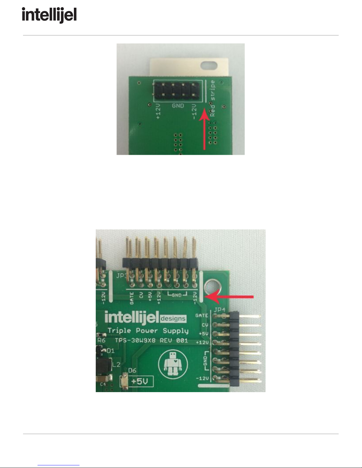
Ensure the 10-pin connector on the power cable is connected correctly to the module before
proceeding. The red stripe on the cable must line up with the -12V pins on the module’s power
connector. The pins are indicated with the label -12V, a white stripe next to the connector, the
words “red stripe”, or some combination of those indicators.
Page 3
JellysquasherManualv1.00
Most modules will come with the cable already connected but it is good to double check the
orientation. Be aware that some modules may have headers that serve other purposes so
ensure the cable is connected to the right one.
The other end of the cable, with a 16-pin connector, connects to the power bus board of your
Eurorack case. Ensure the red stripe on the cable lines up with the -12V pins on the bus board.
On Intellijel power supplies the pins are labelled with the label “-12V” and a thick white stripe:
If you are using another manufacturer’s power supply, check their documentation for
instructions.
Page 4

JellysquasherManualv1.00
Once connected, the cabling between the module and power supply should resemble the
picture below:
Before reconnecting power and turning on your modular system, double check that the ribbon
cable is fully seated on both ends and that all the pins are correctly aligned. If the pins are
misaligned in any direction or the ribbon is backwards you can cause damage to your module,
power supply, or other modules.
After you have confirmed all the connections, you can reconnect the power cable and turn on
your modular system. You should immediately check that all your modules have powered on
and are functioning correctly. If you notice any anomalies, turn your system off right away and
check your cabling again for mistakes.
Page 5
JellysquasherManualv1.00
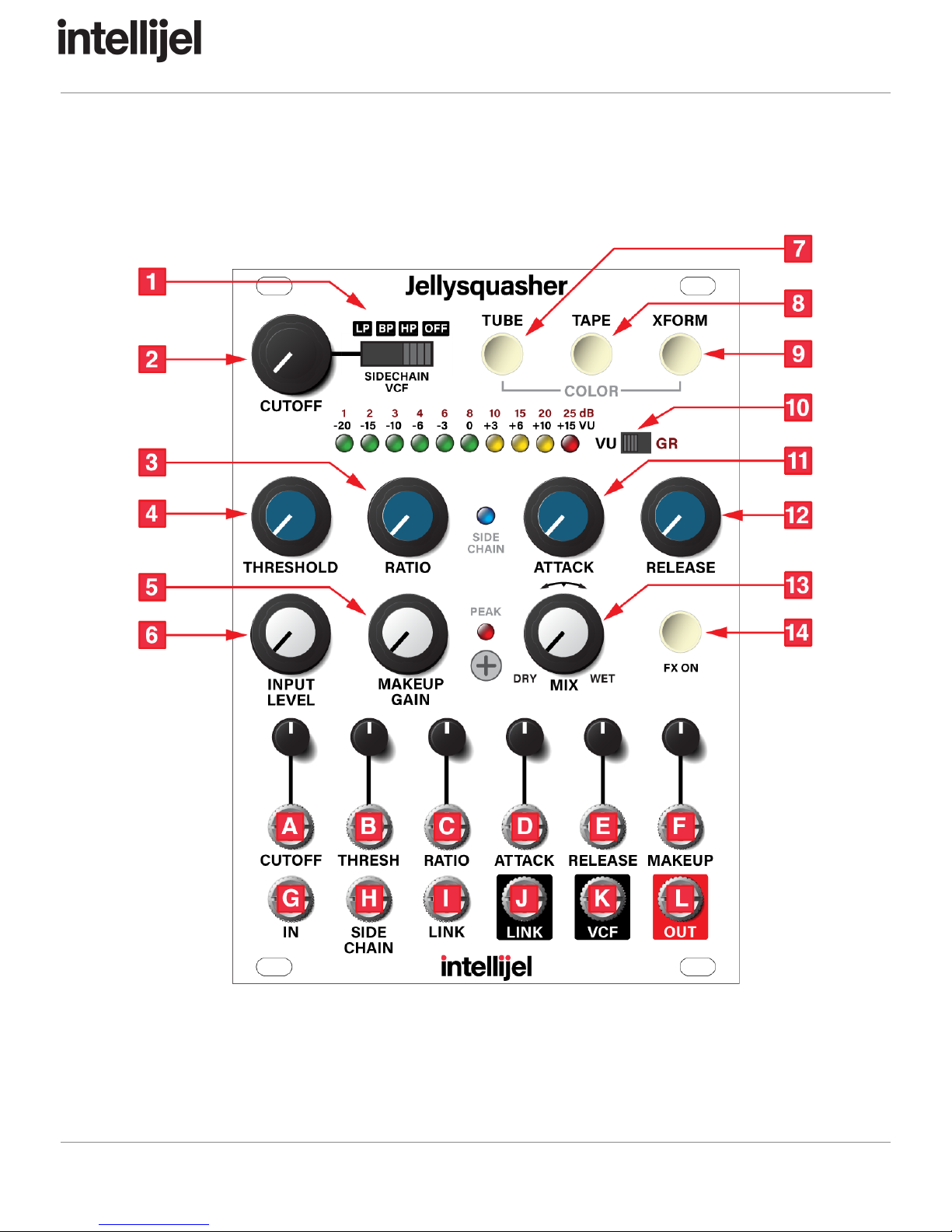
FrontPanel
Page 6

JellysquasherManualv1.00
Controls
1. SIDECHAIN VCF MODE - Selects the mode of the filter applied to the sidechain input.
The options are LP (lowpass filter), BP (bandpass filter), HP (highpass filter) and OFF.
2. CUTOFF - Adjusts the cutoff frequency of the sidechain filter. The filter's Q is fixed but
can be adjusted with a trimmer on the rear of the module.
3. RATIO - Adjusts the compression ratio. The range is from 1.3:1 when fully
counter-clockwise to infinity (hard limiter) at fully clockwise.
4. THRESHOLD - Sets the compression threshold with a range of -40 dB when fully
counter-clockwise to +17 dB when fully clockwise.
5. MAKEUP GAIN - Sets the amount of post-compressor gain. The range is 0 dB to +48
dB.
6. INPUT LEVEL - Sets the gain of the input signal. Unity is at approximately the 2 o'clock
position.
7. TUBE - Engages the tube distortion analog circuit emulation. This adds non-linear
distortion and provides second-order harmonics.
8. TAPE - Engages the tape saturation analog circuit emulation. This adds symmetrical
distortion, providing both odd and even harmonics.
9. XFORM - Modifies the transformer feedback circuit, giving a boost to low-frequency
content. The effect can be subtle but it will add extra bottom-end to kicks and other
signals in the < 100 Hz range.
10. METER MODE - Switches between viewing the compression gain reduction in dB or the
audio output level in VU.
11. ATTACK - Adjusts the compressor attack time. The range is 200 µs to 200 ms.
12. RELEASE - Adjusts the compressor release time. The range is 50 ms to 5 seconds.
13. MIX - Adjusts the ratio of the wet (compressed) to dry (uncompressed input) signals.
This is useful for "New York"-style parallel compression effects.
14. FX ON/OFF - Allows the compressor to be bypassed. When the light is ON the
compressor is active.
InputsandOutputs
A. CUTOFF - CV control of the sidechain filter frequency cutoff. Expected range is ±5 V.
The signal is summed with the panel CUTOFF control.
B. THRES - CV control of the compressor threshold. Expected range is ±5 V. The signal is
summed with the panel THRESHOLD control.
C. RATIO - CV control of the compressor ratio. Expected range is ±5 V. The signal is
summed with the panel RATIO control.
D. ATTACK - CV control of the compressor attack time. Expected range is ±5 V. The signal
is summed with the panel ATTACK control.
Page 7

JellysquasherManualv1.00
E. RELEASE - CV control of the compressor release time. Expected range is ±5 V. The
signal is summed with the panel RELEASE control.
F. MAKEUP - CV control of the compressor makeup gain. Expected range is ±5 V. The
signal is summed with the panel MAKEUP GAIN control.
G. IN - Audio input for the compressor.
H. SIDE CHAIN - Compressor sidechain input. With nothing connected this is taken from
the audio input of the compressor, post gain and filter. You can patch an external source
here instead. A very common use for this is to use a kick drum as the sidechain signal
and the rest of the mix as the input to create a "ducking" effect.
I. LINK (IN) - Connect the LINK (OUT) signal from another Jellysquasher to create a
stereo pair.
J. LINK (OUT) - See LINK (IN)
K. VCF - The output of the VCF circuit. You can use this independent of the compressor by
by patching a signal to the *SIDE CHAIN* input.
L. OUT - Audio output of the Jellysquasher. If the compressor is on (FX is lit) then the
output is post-transformer. If the compressor is bypassed the output passes just the
input signal.
Page 8
JellysquasherManualv1.00
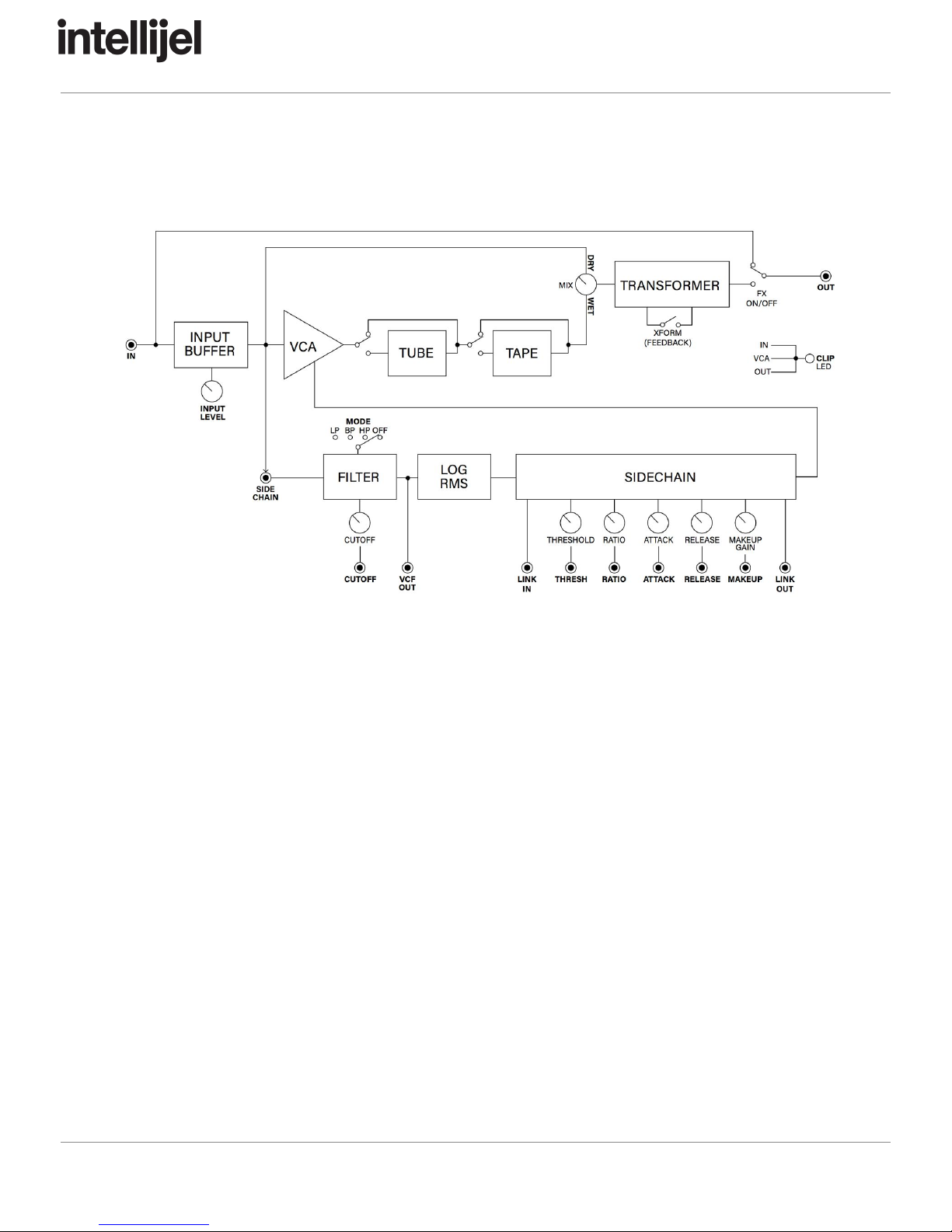
SignalFlowDiagram
Page 9
JellysquasherManualv1.00
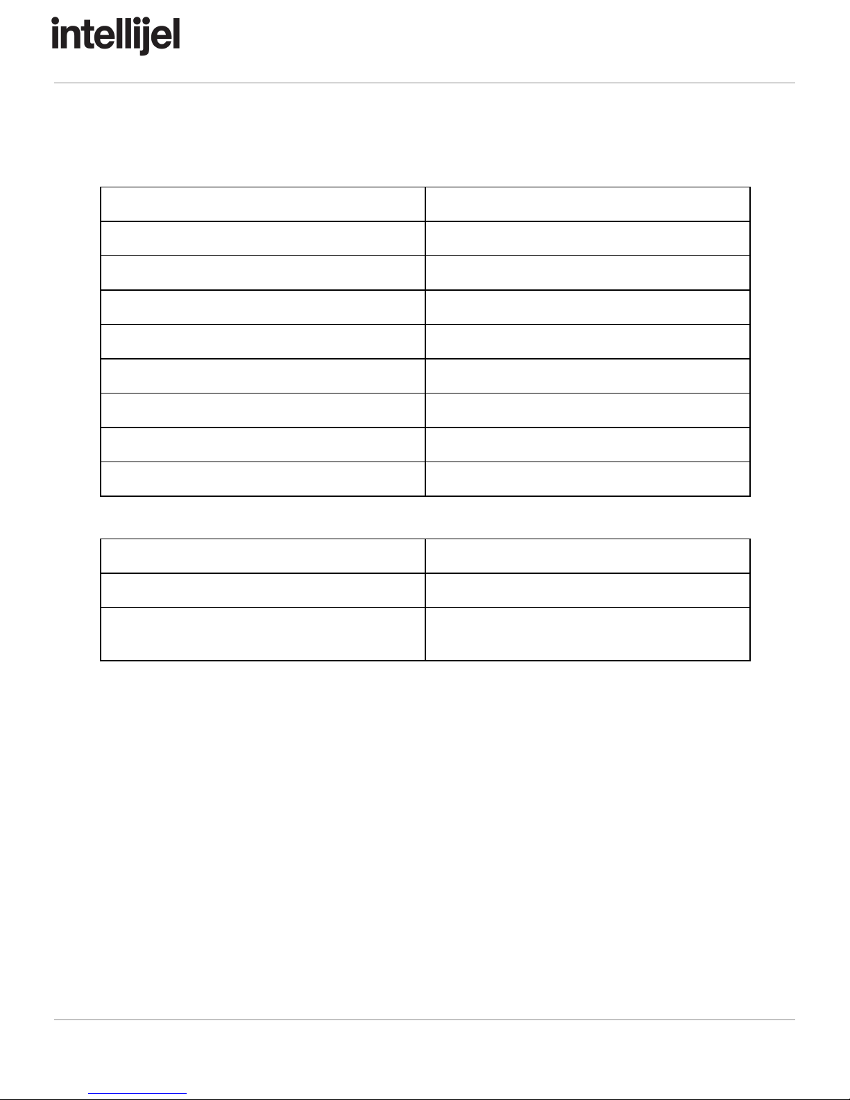
TechnicalSpecifications
Max input
+17 dBv
Input impedance
68 kΩ
Output impedance
100 Ω
Frequency response
5 Hz to 30 kHz
Threshold
-40 dBv to +17 dBv
Ratio
1.3:1 to infinity
Attack
200 µs to 200 ms
Release
50 ms to 5 sec
Makeup gain
48 dB
Width
18 hp
Maximum Depth
42 mm
Current Draw
120 mA @ +12 V
134 mA @ -12 V
Page 10
Table of contents
Popular Air Compressor manuals by other brands


Campbell Hausfeld
Campbell Hausfeld CE7000 Series operating instructions

MayPole
MayPole MP7955 user guide

Aerfast
Aerfast AC09210 operating manual

Kaishan
Kaishan KRSL Series instruction manual

ABAC
ABAC Air Compressor Instructions for use manual

Gardner Denver
Gardner Denver TR20 Rear CW Installation operating & maintenance manual