9 10
COMPRESSOR FEATURES
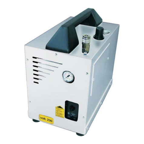
PRESSURE SWITCH:
This switch is used to start or stop the air compressor. Moving the switch to the Auto (On) position will
provide automatic power to the pressure switch which will allow the motor to start when the air tank
pressure is below the factory set cut-in pressure. When in the Start/Stop option, the pressure switch stops
the motor when the air tank pressure reaches the factory set cut-out pressure. This switch also has a
pressure unloading valve located on the side of the switch designed to automatically release compressed
air from the air compressor pump head and its discharge line when the air compressor reaches cut-out
pressure or is chut o. This allows the motor to restart freely. Moving the switch to the O position will
cut-o power and stop the air compressor.
MOTOR THERMAL OVERLOAD PROTECTOR:
The electric motor has a thermal overload protector. if the motor overheats for any reason, the thermal
overload will cut o power, thus preventing the motor from being damaged. Wait until the motor is cool.
The motor also have a magnetic breaker. Reset the switch if it is tripped.
AIR INTAKE FILTER:
The lter is designed to clean air coming into the pump. To ensure the pump continually recieve a clean,
cool and dry air supply this lter must always be clean and ventilation opening free from obstructions. The
lter can be removed for cleaning by using warm, soapy water. Rinse the lter and air dry.
AIR COMPRESSOR PUMP:
To compress air, the piston moves up and down in the cylinder. On the downstroke, air is drawn in through
the air intake valve while the exhaust valve remains closed. On the upstroke, air is compressed, the intake
valve closes and compressed air is forced out through the exhaust valve, into the discharge line, through
the check valve and into the air tank.
SAFETY RELIEF VALVE:
This valve is designed to prevent system failures by relieving pressure from the system when the
compressed air reaches a predetermined level. the valve is preset by the manufacture and must not be
modied in any way. To verify the valve is working properly, pull the ring. Air will escape. When the ring is
released, it will reset.
AIR TANK DRAIN VALVE:
The drain valve is used to remove moisture from the air tank(s) after the air compressor is shut of. NEVER
attempt to open the drain valve when more than 0.7 Bar of air pressure is in the air tank! To open the drain
valve, turnthe knob counterclockwise. Tilt the tank to ensure that all condensation drains through the
valve.
AIR TANK PRESSURE GAUGE:
The air tank pressure gauge indicates the reserve air pressure in the air tank(s)
OUTLET PRESSURE GAUGE:
The outlet pressure gauge indicactes the air pressure available at the outlet side of the regulator. This
pressure is controlled by the regulator and is always less or equal to the air tank pressure.
PRESSURE REGULATOR:
The air pressure coming from the air tank is controlled by the regulator knob. Turn the pressure regulation
knob clockwise to increase discharge pressure and counterclockwise to decrease discharge pressure.
Turn the threat not against the knob to lock.
DISCHARGE LINE:
Please be aware that the discharge line is very hot
PREPARATION
INITIAL SET-UP:
1. Read safety warnings before setting-up air compressor.
LOCATION:
CAUTION
In order to avoid damaging the air compressor, do not incline the air compressor
transversely or longitudinally more than 10•.
DANGER
Improper connection of the equipment-grounding conductor can
result in a risk of shock or electrocution. Check with a qualied
electrician or service personnel if you are in doubt as to whether
the outlet is properly grounded. Do not use any type of adapter
with this product. If repair or replacement of the cord or plug is necessary, do not
connect the grounding wire to either at blade terminal. The wire with insulation
having an outer surface that is green with or without yellow stripes is the
grounding wire.
WARNING
Serious injury or death may occur if electrical sparks from motor
and pressure switch come in contact with ammable vapors,
combustible dust, gases or other combustible materials. When
using the air compressor for spray painting, place the air
compressor as far away I from the work area as possible, using
extra air hoses instead of extension cords.
Place the air compressor at least 30 cm away from obstacles that may prevent proper ventilation.
Do not place air compressor in an area:
-where there is evidence of oil or gas leaks.
-where ammable gas vapors or materials may be present.
-where air temperatures fall below 0•C or exceed 40•C .
-where extremely dirty air or water could be drawn into the air compressor.
WARNING
This product must be grounded. If there should be a malfunction or
breakdown, grounding provides a path of least resistance for
electric current to reduce the risk of electric shock. This product is
equipped with a cord having an equipmentgrounding conductor and
a grounding type plug. The plug must be plugged into an appropriate outlet that is
properly installed and grounded in accordance with all local codes and
ordinances.
GROUNDING INSTRUCTIONS:
Do not modify the plug that has been provided, if it does not t the available outlet, the correct outlet
should be installed by a qualied electrician. The plug must be plugged into an outlet that is properly
installed and grounded in accordance with all local codes. If these grounding instructions are not com-
pletely understood or if in doubt as to whether the compressor is properly grounded, have the installation
checked by a qualied electrician.
This product is for use on a nominal 115 or 230 volt circuit, as applicable. A cord with a grounding plug as
shown here shall be used. Make sure that the product is connected to an outlet that matches the plug. No
adapter should be used with this product
(FOR AREA OTHER THAN USA, PLEASE CHECK THE LOCAL CODE.)
GB GB


