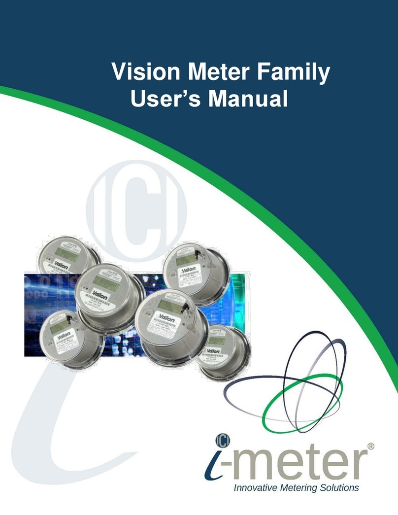
Intellimeter I-METER 45 User manual

I-METER ®45
INSTALLATION AND
USER MANUAL

Page 2
Intellimeter Canada Inc.
1125 Squires Beach Road, Pickering, ON, L1W 3T9 • Tel: (905) 839-9199
Copyright 2019 © i-meter 45 Manual
TABLE OF CONTENTS
1. PRODUCT DESCRIPTION..................................................................................................................4
1.1. Applications .......................................................................................................................................4
1.2. Specifications.....................................................................................................................................5
2. INSTALLATION................................................................................................................................6
2.1. i-meter®45 Wiring Guide...................................................................................................................6
2.2. i-meter®45 (CT Rail)...........................................................................................................................7
2.3. i-meter®45 (CT Interface Board)......................................................................................................10
3. I-METER®45 MDU DISPLAY ...........................................................................................................15
4. i-meter®45 MODBUS MODULE .............................................................................................................15
4.1 Electrical connection........................................................................................................................16
4.2 Register Mapping.............................................................................................................................17

Page 3
Intellimeter Canada Inc.
1125 Squires Beach Road, Pickering, ON, L1W 3T9 • Tel: (905) 839-9199
Copyright 2019 © i-meter 45 Manual
WARNING
Field electrical installers must follow proper safety precautions and all local electrical code requirements
during electrical installation, meter wiring, and CT installation. During normal operation of this device,
hazardous voltages are present which can cause severe injury or death. It is strongly recommended that
only qualified, properly trained personnel should perform installation and servicing.
DISCLAIMER
The information presented in this publication has been carefully checked; however, Intellimeter Canada
Inc. (ICI) assumes no responsibility for inaccuracies. The information provided in this document is
subject to change without notice.
CUSTOMER SUPPORT
To report any issue, please contact ICI at 905.839.9199. Prior to returning any merchandise to ICI, a
return material authorization (RMA) number should be obtained from ICI.
STATEMENT OF CALIBRATION
The accuracy and calibration of our instruments are traceable to Measurement Canada, a division of
Industry Canada.
CONFIGURATION
The i-meter®45-meter series can only be configured by Intellimeter Canada Inc. at ICI’s factory according
to the customers provided panel schedule.
INSTALLATION CHECKLIST
Make sure you have received the right meter as per your order and packing list.
INSTALLATION DISCLAIMER
INTELLIMETER does not accept any responsibility and will not be liable for any loss or damage or
expense of any kind whatsoever and howsoever caused by improper installation of its products, be it
indirect, special, incidental or consequential damages (including but not limited to damages for loss of
business, loss of profits, interruption or the like). Please refer to Intellimeter's Terms and Conditions of
Sale available at https://intellimeter.ca/pages/terms-of-service-privacy-statement
ELECTRICAL CODE
Installer is responsible for ensuring that all safety and local electrical codes are followed.

Page 4
Intellimeter Canada Inc.
1125 Squires Beach Road, Pickering, ON, L1W 3T9 • Tel: (905) 839-9199
Copyright 2019 © i-meter 45 Manual
1. PRODUCT DESCRIPTION
The i-meter®45 is a next generation multi-customer metering system (MCMS) It supports up to 45 current
inputs, programmable for single or poly-phase applications. From 120V to 347V (60/50Hz) Line to Neutral
Voltages
(L-N). The i-meter®45 uses the latest generation of DSP (Digital Signal Processor) technology to provide
an extended range of software configurable features, alphanumeric display and power quality monitoring
in real time; with multiple communication options.
The i-meter®45 is a self-powered meter using a wide range switching power supply. It has been approved
by Measurement Canada (MC) and Measurement California, and certified by CSA & UL.
i-meter®45 meter
1.1. Applications
The i-meter®45 is designed for a wide variety of applications. In Multi-Customer Metering systems
(MCMS) applications, property managers can use the data for cost allocation and demand side
management.
This meter can be programmed for different service types. They are:
Single phase two wire: metering capability of up to 45 meters
Single phase three wire: metering capability of up to 22 meters
Two phase three wire: metering capability of up to 22 meters
Three phase four wire: metering capability of up to 15 meters
Or any combinations of above
The meter provides cumulative energy consumption data for each meter.
All current transformers(CTs) are self-protected.
Note: Any changes to the original configuration will need to be coordinated with Intellimeter Canada
Inc. Please contact service@intellimeter.ca for inquiries and assistance.

Page 5
Intellimeter Canada Inc.
1125 Squires Beach Road, Pickering, ON, L1W 3T9 • Tel: (905) 839-9199
Copyright 2019 © i-meter 45 Manual
1.2. Specifications
Dimensions (Inches)
16.5 H x 4.5 W x 2 D
Dimensions (Millimeters)
420 H x 115 W x 45 D
Mounting Options
Externally mount with loose CT’s
Meter Current Inputs
1 to 45
Voltage Rating
Auto range 120-347VAC (L-N), -20% to +10% of rating
Rated VA
< 12 VA
Current Range
CTs Primary 0 –600A, CTs Secondary 0 –0.1A
Meter Constant (Kh)
1Wh, 1VAh or 10Wh, 10VAh or 100Wh, 100VAh
Service type:
1Φ2W, 1Φ3W, 2Φ3W, 3Φ4W, 3Φ3W (Delta*)
Current Transformers
Secondary Max 80/100mA CTs, Self-Shorting Protection
Instrument Transformers Interface
Yes
Measurements
•Total Energy: kWh, kVAh are accumulated in non-volatile memory on
the meter
•Real Time Measurements: V, I, kW, kVA, kVar, pf, Hz, Per phase V & I
Total Harmonic Distortion (THD), Per phase V & I individual harmonic
order up to 23rd
Communication
ModBus RTU or TCP/IP, BACnet MSTP or TCP/IP and pulse output.
Frequency
45 to 65 Hz
Accuracy Class
0.5 (Meets ANSI C12.20)
Total Energy
kWh, kVAh are accumulated in non-volatile memory on the meter
Real Time Measurements
V, I, kW, kVA, kVar, pf, Hz, Per phase V & I Total Harmonic Distortion
(THD), Per phase V & I individual harmonic order up to 23rd
Operating Temperature
-10°C to +53°C
Regulatory Compliance / Approvals
Measurement Canada,
CCSAUS
,
CULUS
, CTEP (CA)
Patent
U.S. Patent No. 8,049,488

Page 6
Intellimeter Canada Inc.
1125 Squires Beach Road, Pickering, ON, L1W 3T9 • Tel: (905) 839-9199
Copyright 2019 © i-meter 45 Manual
2. INSTALLATION
You can visit https://intellimeter.ca/pages/downloads#videos / Intellimeter i-meter®45 Installation
&Troubleshooting to get detailed information about the installation process.
WARNING:
Verify the number of breakers is the same as the number of meters assigned for that panel board.
Follow the installation drawings. Group the assigned modules to the identified panel board.
Referring to the diagram below, CTs can be embedded in the distribution panel. If the customer
has supplied a special compartment for the meter with their electrical panel, Intellimeter will
install the meter and have the SPE-1000 field evaluation completed. Otherwise, the meter will be
installed in an external enclosure to be mounted near the electrical panel for ease of servicing.
Install the modules into their appropriate position.
Install the voltage connectors to the meter modules and dress the wires so they are protected
from damage during feeder and branch circuit installation.
Terminate the voltage reference chain to the designated, 15Amp breaker and ensure the proper
phasing retained as per drawings.
Install the communication connectors to the meter modules and dress the wires they are
protected from damage during feeder and branch circuit installation.
Communication cable is to be terminated to a junction box outside of the panel board by the
electrical contractor.
2.1. i-meter®45 Wiring Guide
In the i-meter®45 wiring diagram figure below, the branch CTs connect to Port A, B, C, D using a
ribbon cable.
Port A: CT1 –CT12
Port C: CT13 –CT21
Port B: CT22 –CT33
Port D: CT34 –CT42
CT43, CT44, CT45 are connected directly to the meter module with 2 pin connectors.
Voltage Input: L1, L2, L3 and N
Display- MC required- optional only if non-sealed: i-meter®45 MDU = meter display unit- comes
with a 6 ft. cable for connecting directly to the meter.

Page 7
Intellimeter Canada Inc.
1125 Squires Beach Road, Pickering, ON, L1W 3T9 • Tel: (905) 839-9199
Copyright 2019 © i-meter 45 Manual
i-meter®45 wiring diagram
2.2. i-meter®45 Current transformers (CT) Rail
Review general information and wiring diagram.
Carefully read all the WARNING signs and notes.
Check meter serial number and other information on the meter.
All meter modules are assigned within the panel board and are identified with respect to
position, or section of breakers.
Follow the installation drawings that are supplied with the units.
Do not leave the secondary CT open when current is flowing through the primary circuit. This
refers to instrument CTs as ICI milliamp CTs are self-protected.
Contact ICI if there has been a change made to the layout or if the assigned drawings do not
match the actual distribution panel layout.

Page 8
Intellimeter Canada Inc.
1125 Squires Beach Road, Pickering, ON, L1W 3T9 • Tel: (905) 839-9199
Copyright 2019 © i-meter 45 Manual

Page 9
Intellimeter Canada Inc.
1125 Squires Beach Road, Pickering, ON, L1W 3T9 • Tel: (905) 839-9199
Copyright 2019 © i-meter 45 Manual
Typical Application Using CT rail
Typical Application Using CT rail

Page 10
Intellimeter Canada Inc.
1125 Squires Beach Road, Pickering, ON, L1W 3T9 • Tel: (905) 839-9199
Copyright 2019 © i-meter 45 Manual
2.3. i-meter®45 Current Transformers (CT) Interface Board
Referring to the installation drawings, mount the module, complete with mounting brackets,
to the back frame rail.
The CT rails are to be permanently fastened to the interior panel rails in their designated
position; this serves for spacing and support for the CTs.
Dress in the CT wire back to the metering modules to protect it from damage during feeder
and branch circuit installations.
Any CT that is not connected to the proper metering module will give incorrect readings.
All CT wire connectors and terminal position on the meter module are identified. Polarity of CT
is VERY important- white is positive, black is negative- note arrow for load/line direction.
Typically, the CT leads do not need to be removed from the meter module. If required, connect
the CT wire connector to the identified terminal on the correct meter module. There may be
several modules within a panel board, confirm the meter number on the CT connector label.
Install the voltage connectors to the meter modules and dress the wires so they are protected
from damage during feeder and branch circuit installation.
Terminate the voltage reference chain to the designated 15Amp breaker and ensure the
proper phasing retained as per drawings.
Install the communication cables to the meter modules and dress the wires so they are
protected from damage during feeder and branch circuit installation.
Communication cable is designed to be terminated to a junction box outside of the panel
board by the electrical contractor.
The 12 CT rail can replace the requirement for the CT interface box in certain situations. The CTs
must be mounted on a rail and the loads should be 100A or 200A. If there are any 400A or 600A
loads, the CT interface box must still be used.

Page 11
Intellimeter Canada Inc.
1125 Squires Beach Road, Pickering, ON, L1W 3T9 • Tel: (905) 839-9199
Copyright 2019 © i-meter 45 Manual
12 CT rail for 100A CTs
12 CT rail for 200A CTs

Page 12
Intellimeter Canada Inc.
1125 Squires Beach Road, Pickering, ON, L1W 3T9 • Tel: (905) 839-9199
Copyright 2019 © i-meter 45 Manual
The i-meter®45 CT terminal board

Page 13
Intellimeter Canada Inc.
1125 Squires Beach Road, Pickering, ON, L1W 3T9 • Tel: (905) 839-9199
Copyright 2019 © i-meter 45 Manual
Current Transformer Interface Module:

Page 14
Intellimeter Canada Inc.
1125 Squires Beach Road, Pickering, ON, L1W 3T9 • Tel: (905) 839-9199
Copyright 2019 © i-meter 45 Manual
Typical Application Using CT Terminal Board

Page 15
Intellimeter Canada Inc.
1125 Squires Beach Road, Pickering, ON, L1W 3T9 • Tel: (905) 839-9199
Copyright 2019 © i-meter 45 Manual
3. i-meter®45 METER DISPLAY MODULE (MDU DISPLAY)
The Meter Display Module (i-meter®45 MDU) displays customer information, real time measurements,
total energy consumption, and power quality of each customer by using the key pad “UP”, “DOWN” and
“SELECT”.
i-meter®45 MDU Display
4. i-meter®45 MODBUS MODULE
The i-meter®45 ModBus module enables the meter to communicate on a ModBus system. It presents
real time measurements, such as voltage, current, THD etc. The normal mode of the module supports
RTU ModBus communication over an RS-485 network. Within 30 seconds of power up, the module will
enter the normal mode of operation that supports ModBus communication. By default, the module
communicates at 9600 bps, 8 data bits, no parity and 1 stop bit (8N1). The communication parameters
and ModBus ID may be changed through the ModBus registers or through the Recovery Mode.

Page 16
Intellimeter Canada Inc.
1125 Squires Beach Road, Pickering, ON, L1W 3T9 • Tel: (905) 839-9199
Copyright 2019 © i-meter 45 Manual
4.1 Electrical connection

Page 17
Intellimeter Canada Inc.
1125 Squires Beach Road, Pickering, ON, L1W 3T9 • Tel: (905) 839-9199
Copyright 2019 © i-meter 45 Manual
4.2 Register Mapping
Table 4-1 Configuration Parameters
Modbus Address
Name
Format
Access
Default
40003
Firmware Version
UINT16
41002
Address
UINT16
R/W
1
41003
Baud Rate
Enumated
R/W
3 = 9600 bps
Note
1. Address - 41002: Changes to the ModBus address takes effect immediately. The
next command must use the changed address, otherwise the module will not
respond.
2. Baud Rate - 41003: 3 = 9600 bps; 4 = 19200 bps; 5 = 38400 bps; 6 = 57600 bps; 7 =
115200 bps. The Baud Rate takes effect after power cycling.
Table 5-2 Meter 0 Information
Modbus Address
Name
Format
Unit
Default
41100
Active Phases
Bit map
x1
41101
Voltage A
UINT32
0.001V
41103
Voltage B
UINT32
0.001V
41105
Voltage C
UINT32
0.001V
41107
Current A
UINT32
0.001A
41109
Current B
UINT32
0.001A
41111
Current C
UINT32
0.001A
41113
Watts A
INT32
W
41115
Watts B
INT32
W
41117
Watts C
INT32
0.001W
41119
Volt-Amp A
INT32
VA
41121
Volt-Amp B
INT32
VA
41123
Volt-Amp C
INT32
0.001VA
41131
Power Factor A
INT32
0.001 Units
41133
Power Factor B
INT32
0.001 Units
41135
Power Factor C
INT32
0.001 Units
41143
kWh
UINT32
0.001kWh

Page 18
Intellimeter Canada Inc.
1125 Squires Beach Road, Pickering, ON, L1W 3T9 • Tel: (905) 839-9199
Copyright 2019 © i-meter 45 Manual
41145
kVAh
UINT32
001kVAh
41149
Frequency
UINT32
0.01 Hz
41155
Voltage Average
UINT32
0.001V
41157
Meter Total Current
UINT32
0.001A
41161
Meter Total Watts
UINT32
0.001kWh
41163
Meter Total VA
UINT32
0.001kVA
Note
1. Active Phases - 41100: 0x0001 - Meter uses phase A; 0x0002 - Meter uses phase B;
0x0004 - Meter uses phase C.
2. Voltage Average - 41155: Average of the voltage from each phase.
3. Meter Total Current - 41157: Average of the current from each phase.
4. Meter 0 is assigned to the main meter if you program the configuration with main
meter.
Table 5-3 Meter x Information
Modbus Address
Name
Format
Unit
Default
4xx00
Active Phases
Bit map
x1
4xx01
Voltage A
UINT32
0.001V
4xx03
Voltage B
UINT32
0.001V
4xx05
Voltage C
UINT32
0.001V
4xx07
Current A
UINT32
0.001A
4xx09
Current B
UINT32
0.001A
4xx11
Current C
UINT32
0.001A
4xx13
Watts A
INT32
W
4xx15
Watts B
INT32
W
4xx17
Watts C
INT32
W0.001kW
4xx19
Volt-Amp A
INT32
VA
4xx21
Volt-Amp B
INT32
VA
4xx23
Volt-Amp C
INT32
0.001kVA
4xx31
Power Factor A
INT32
0.001 Units
4xx33
Power Factor B
INT32
0.001 Units
4xx35
Power Factor C
INT32
0.001 Units
4xx43
kWh
UINT32
0.001kWh

Page 19
Intellimeter Canada Inc.
1125 Squires Beach Road, Pickering, ON, L1W 3T9 • Tel: (905) 839-9199
Copyright 2019 © i-meter 45 Manual
4xx45
kVAh
UINT32
0.001kVAh
4xx49
Frequency
UINT32
0.01 Hz
4xx55
Voltage Average
UINT32
0.001V
4xx57
Meter Total Current
UINT32
0.001A
4xx61
Meter Total Watts
UINT32
0.001kW
4xx63
Meter Total VA
UINT32
0.001kVA
Note
1. The "xx" = 12+ n, where n = 0, 1 ... 44. For an example, meter 24 (n = 23), xx =
(12+23) = 35, so the start address of meter 24 shall be 43500;
2. Active Phases - 4xx00: 0x0001 - Meter uses phase A; 0x0002 - Meter uses phase B;
0x0004 - Meter uses phase C.
3. Voltage Average - 4xx55: Average of the voltage from each phase.
4. Meter Total Current - 4xx57: Average of the current from each phase.
Table 5-5 Harmonic Register Map
Modbus Address
Name
Format
Unit
Description/Format
47xxx
Meter
Enum
The meter that this element is associated with
47xxx+1
THD
UINT16
0.01%
Total harmonic distortion for this waverform
47xxx+2
Fundamental
UINT16
0.01%
Fundamental component for this waveform
47xxx+3
2nd
Harmonic
UINT16
0.01%
2nd harmonic component for this waveform
47xxx+4
3rd Harmonic
UINT16
0.01%
3rd harmonic component for this waveform
47xxx+5
4th Harmonic
UINT16
0.01%
4th harmonic component for this waveform
47xxx+6
5th Harmonic
UINT16
0.01%
5th harmonic component for this waveform
47xxx+7
6th Harmonic
UINT16
0.01%
6th harmonic component for this waveform
47xxx+8
7th Harmonic
UINT16
0.01%
7th harmonic component for this waveform
47xxx+9
8th Harmonic
UINT16
0.01%
8th harmonic component for this waveform
47xxx+10
9th Harmonic
UINT16
0.01%
9th harmonic component for this waveform
47xxx+11
10th
Harmonic
UINT16
0.01%
10th harmonic component for this waveform
47xxx+12
11th
Harmonic
UINT16
0.01%
11th harmonic component for this waveform
47xxx+13
12th
Harmonic
UINT16
0.01%
12th harmonic component for this waveform

Page 20
Intellimeter Canada Inc.
1125 Squires Beach Road, Pickering, ON, L1W 3T9 • Tel: (905) 839-9199
Copyright 2019 © i-meter 45 Manual
47yyy
Meter
Enum
The meter that this element is associated with
47yyy+1
THD
UINT16
0.01%
Total harmonic distortion for this waverform
47yyy+2
Fundamental
UINT16
0.01%
Fundamental component for this waveform
47yyy+3
2nd
Harmonic
UINT16
0.01%
2nd harmonic component for this waveform
47yyy+4
3rd Harmonic
UINT16
0.01%
3rd harmonic component for this waveform
47yyy+5
4th Harmonic
UINT16
0.01%
4th harmonic component for this waveform
47yyy+6
5th Harmonic
UINT16
0.01%
5th harmonic component for this waveform
47yyy+7
6th Harmonic
UINT16
0.01%
6th harmonic component for this waveform
47yyy+8
7th Harmonic
UINT16
0.01%
7th harmonic component for this waveform
47yyy+9
8th Harmonic
UINT16
0.01%
8th harmonic component for this waveform
47yyy+10
9th Harmonic
UINT16
0.01%
9th harmonic component for this waveform
47yyy+11
10th
Harmonic
UINT16
0.01%
10th harmonic component for this waveform
47yyy+12
11th
Harmonic
UINT16
0.01%
11th harmonic component for this waveform
47yyy+13
12th
Harmonic
UINT16
0.01%
12th harmonic component for this waveform
Note
1. The "xxx" = 000, 010, ..., (000 + 10n), where (n+1) is the number of CTs or Current inputs, n =
0, 1, ..., 44. 2. The "yyy" = 460 (Voltage A), 480
(Voltage B), 500 (Voltage C),
Table of contents
Other Intellimeter Measuring Instrument manuals
Popular Measuring Instrument manuals by other brands

AvionTEq
AvionTEq HEATCON HCS9000B Operation and maintenance manual

Woodcraft
Woodcraft Wood River 163732 instruction manual
Compressed Air Alliance
Compressed Air Alliance POM200 user manual

Jadak
Jadak PHOTO RESEARCH CINEBRATE PR-653 user manual
Vesta
Vesta PRM2-ZW-P5 quick start guide
RADEX
RADEX RD1212-BT quick start guide
