Vesta PRM2-ZW-P5 User manual

1
PRM2-ZW-P5
Z-Wave Power Relay Switch with Meter
Introduction
The Power Relay Switch is capable of receiving wireless signals from the coordinator in the Z-Wave network to
toggle On/Off of appliances that are attached to it.
The Power Relay Switch is a Z-Wave enabled device and is fully compatible with any Z-Wave enabled network.
Z-Wave is a wireless communication protocol that uses a low-power RF radio. By taking advantage of the
Z-Wave mesh network, commands can be transmitted to their destination via intermediary “listening” Z-Wave
products.
PRM2-ZW-P5 have the extra feature of keeping tracks of energy consumption with built-in power meter and
transmit the data to coordinator regularly.
PRM2-ZW-P5 also serve as a router in the Z-Wave network. After being included in the Z-Wave network, it allows
other Z-Wave device to join the network through the Power Switch.
Parts Identification
1. LED indicator
The LED indicator is used to indicate Power Relay Switch status:
- On:
The Power Relay Switch is turned on.
- Off:
The Power Relay Switch is turned off.
- Flashes twice:
The Power Relay Switch has successfully added into Z-Wave network.
- Flashes three times
The Power Relay Switch has successfully bound with a controller.
- Flashes five times
The Power Relay Switch was unable to bind with a controller.
2. Function Button
The function button is used to control the Power Relay Switch:
Function Button Usage:
- Press the button to toggle on/off the Power Relay Switch
- Press the button 3 times within 1.5 seconds to send a learn code.
- Press and hold the button for 3 seconds then release to bind with a controller
- Press and hold the button for 10 seconds to factory reset.
3. External Switch Terminal 1
4. External Switch Terminal 2
5. AC Line Power Input
6. AC Neural Power Input
7. AC Neutral Power Load Output
8. AC Line Power Load Output
A
Ad
dd
di
in
ng
g
D
De
ev
vi
ic
ce
e
(
(I
In
nc
cl
lu
us
si
io
on
n)
)
This product can be included and operated in any Z-Wave network with other Z-Wave certified devices from
other manufactures and/or other applications. All non-battery operated nodes within the network will act as
repeaters regardless of vendor to increase reliability of the network.
Connect the Power Relay Switch to power cable.
The Power Relay Switch will emit a 2-tone beep.
Put the Z-Wave gateway or control panel into Inclusion or Learning mode (please refer to the
Z-Wave gateway or control panel manual).
Within 1.5 seconds, press the Function Button 3 times. The Power Relay Switch will emit a 2-tone
beep.

2
Refer to the operation manual of the Z-Wave gateway or control panel to complete the learn-in
process.
If the sensor has already been included (learnt) into another Z-Wave Gateway/Control Panel, or if
the sensor is unable to be learnt into the current Z-Wave Gateway/Control Panel, please exclude it
first (see Exclusion) before attempting to include it into the current Z-Wave Gateway/Control
Panel.
R
Re
em
mo
ov
vi
in
ng
g
D
De
ev
vi
ic
ce
e
(
(E
Ex
xc
cl
lu
us
si
io
on
n)
)
The Power Relay Switch must be removed from existing Z-Wave network before being included into
another. There are two methods available to exclude a device.
Exclusion Mode
Put the Z-Wave gateway or control panel into Exclusion mode (please refer to the Z-Wave
gateway or control panel manual).
Within 1.5 seconds, press the Function Button 3 times and the Power Relay Switch will be removed
from the Z-Wave network.
Factory Reset
(Only use factory reset when network Control Panel/Gateway is missing or inoperable).
Press and hold the Function Button for 10 seconds to factory reset.
<
<N
NO
OT
TE
E>
>
Factory resetting the Power Relay Switch will restore it to factory default settings (excluded from the
Z-Wave network). The Z-Wave gateway or control panel will still keep its Z-Wave settings. Please
refer to the gateway or control panel manual on how to remove the Power Relay Switch’s Z-Wave
settings.
R
Ra
an
ng
ge
e
T
Te
es
st
t
To test whether the device is able to communicate with the Z-Wave gateway or control panel:
Put the gateway / panel into range test mode (Walk Test).
Press the Function Button on the device.
The gateway / panel should display if the device is within the operation range (please refer to the
operation manual of the gateway / panel).
Z
Z-
-W
Wa
av
ve
e
S
Sl
le
ee
ep
p
M
Mo
od
de
e
The Power Relay Switch will enter Z-Wave Sleep mode (to conserve power) after waking up for a
short period of time (~10 seconds). While in Z-Wave sleep mode, Z-Wave gateways or control
panels are unable to send commands to the Power Relay Switch.
To program the Power Relay Switch, please send command(s) to the Power Relay Switch within the
wake-up period.
B
Bi
in
nd
di
in
ng
g
w
wi
it
th
h
C
Co
on
nt
tr
ro
ol
ll
le
er
r
After joining the Z-Wave network, the Power Relay Switch can bind itself with a controller device which can
be used to adjust the Power Relay Switch’s power output level. To bind the Power Relay Switch and the
device:
1. Press and hold the Function Button for 3 seconds, then release the button. The Power Relay Switch will
send binding request to the coordinator.
2. Refer to your controller manual to send binding request for the device within 16 seconds.
3. If binding is successful, the Power Relay Switch LED indicator will flash 3 times to confirm. You can now
use the controller to adjust power output level for the Power Relay Switch.
4. If binding is unsuccessful, the Power Relay Switch LED indicator will flash 5 times. Please retry the
binding process.
Operation
W
Wi
ir
re
e
C
Co
on
nn
ne
ec
ct
ti
io
on
n
D
Di
ia
ag
gr
ra
am
m
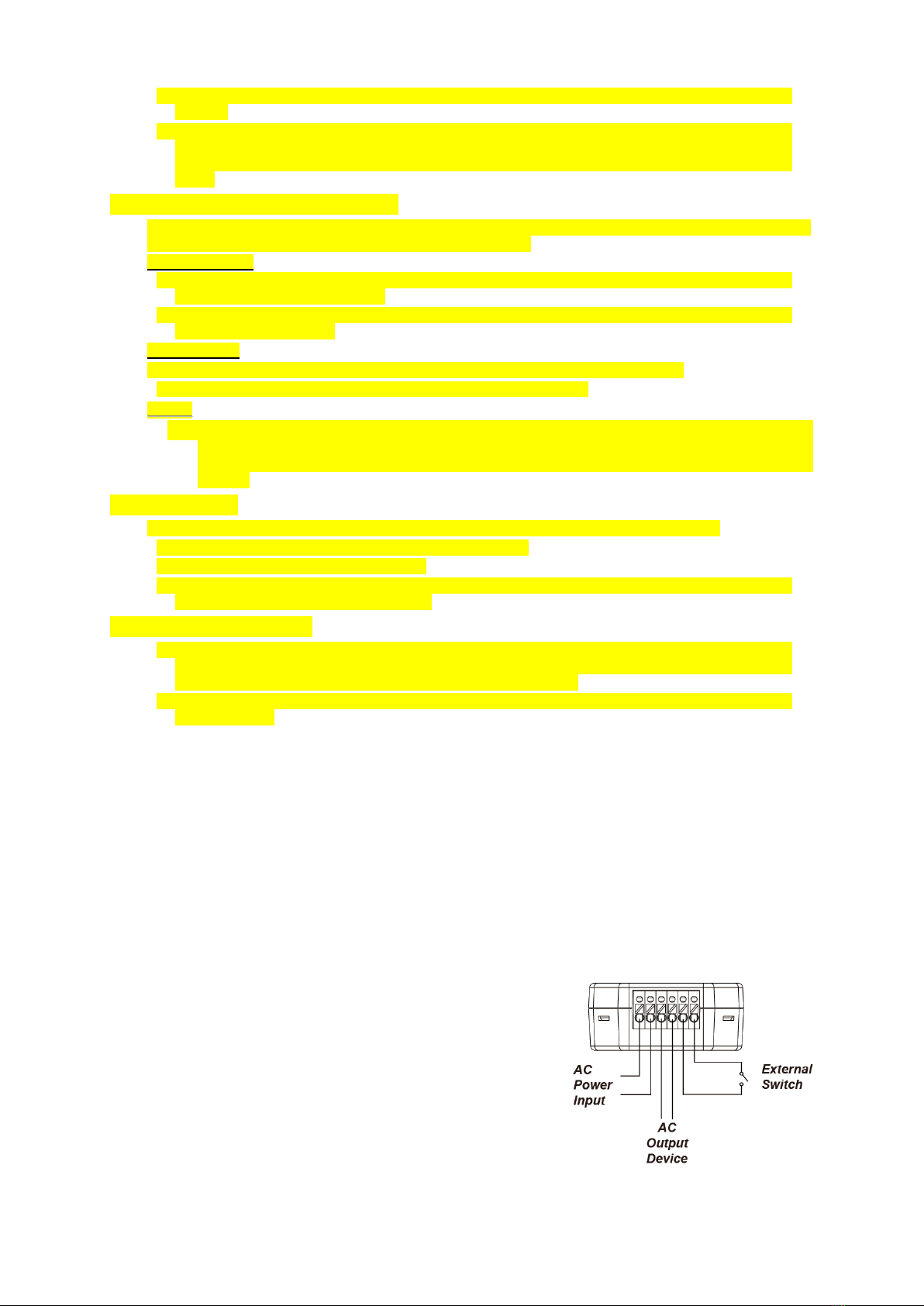
Refer to the diagram to connect your home lighting to the
Power Relay Switch.
I
In
ns
st
ta
al
ll
la
at
ti
io
on
n
Connect the Power Relay Switch to power cable.
Connect the power cable to your home lighting. The lighting
must be in ON status.
You can connect an external switch to the Power Relay
Switch according to the diagram to turn on/off the Power
Relay Switch.
IMPORTANT NOTE: The Power Relay Switch does not have a backup battery and will be powered
down when AC power fails. DO NOT use the Power Relay Switch as router for your security sensor or
alarm control devices such as Door Contact, PIR Sensor…etc., otherwise the sensors will lose

3
connection to Z-Wave network if the Power Relay Switch is disconnected from AC power. Plan the
installation locations of these security sensors without using the Power Relay Switch and only use a
router with backup battery for them. The router function of the Power Switch should ONLY be used to
provide signal range extension for other Power Switches/Dimmer.
A
Ap
pp
pl
li
ia
an
nc
ce
e
C
Co
on
nt
tr
ro
ol
l
After the Power Relay Switch has successfully joined a Z-Wave network, the coordinator can remotely
turn on/off the Appliance.
You can also press the button on the Power Relay Switch to toggle on/off the light.
You can turn on/off the Power Relay Switch with an external switch.
If you have bound a controller with the Power Relay Switch, you can also use the controller to turn
on/off the Power Relay Switch.
If the AC Power input is disconnected from the Power Relay Switch, its previous on/off status will be
restored within 1 minute after reconnecting theAC Power input to the Power Relay Switch.
E
En
ne
er
rg
gy
y
C
Co
on
ns
su
um
mp
pt
ti
io
on
n
M
Mo
on
ni
it
to
or
r
The Power Relay Switch will transmit a signal with its power consumption data every two minutes to
the Z-Wave network coordinator.
Whenever the Power Switch energy output changes by +/- 2W, it will automatically transmit a signal
with power consumption data to the Z-Wave network coordinator for update.
The Power Switch transmits a signal with power data to coordinator whenever accumulated power
usage increases by 0.1kW/hr.
The Meter has an accuracy of +/- 5%.
To clear the Power Switch of its accumulated power consumption data, follow steps below:
1. Disconnect the Power Relay Switch from power outlet.
2. Press and hold the function button and reconnect power when holding down the button.
3. Keep holding the button and release after 3 seconds. The accumulated power consumption data
will be cleared.
M
Ma
ax
xi
im
mu
um
m
O
Op
pe
er
ra
at
ti
io
on
n
L
Lo
oa
ad
d
For 110V: the maximum operation load is 1100W and 10A.
For 230V: the maximum operation load is 2300W and 10A.
If the Power Relay Switch is overheating, it will cut off power automatically as a safety measure. The
user must disconnect and reconnect AC power to the Power Relay Switch after cut off to resume
normal operation.
Z
Z-
-W
Wa
av
ve
e
I
In
nf
fo
or
rm
ma
at
ti
io
on
n
Device Type: On/Off Power Switch
Role Type: Always On Slave (AOS)
Command Class Support/Control
Mandatory CC Support: Association CC, v2 or newer
Association Group Information CC
Meter CC, v2
Basic CC
Binary Switch CC
Device Reset Locally CC
Manufacturer Specific CC
Powerlevel CC
Version CC, v2 or newer
Z-Wave Plus Info CC
Recommended CC Support: Firmware Update Metadata CC
Z
Z-
-W
Wa
av
ve
e’
’s
s
G
Gr
ro
ou
up
ps
s
(
(A
As
ss
so
oc
ci
ia
at
ti
io
on
n
C
Co
om
mm
ma
an
nd
d
C
Cl
la
as
ss
s
V
Ve
er
rs
si
io
on
n
2
2)
)
The Switch can be set to send reports to associated Z-Wave devices. It supports one association group
with five node support for Grouping 1. For grouping 1, the Switch will report its latest status to Z-Wave
Gateway/Panel.
Grouping 1 includes:
Binary Switch CC (SWITCH_BINARY_REPORT)
Meter CC, v2 (METER_REPORT_COMMAND)
Device Reset Locally CC (COMMAND_CLASS_DEVICE_RESET_LOCALLY)
Auto report to Grouping 1 (Maximum Node 5)
On/Off Event Report
When toggling between On/Off, it will send Binary Switch Report to the nodes of Grouping 1.
Table of contents
Other Vesta Measuring Instrument manuals
Popular Measuring Instrument manuals by other brands

Cateye
Cateye VELO WIRELESS Plus CC-VT210W quick start

Hanna Instruments
Hanna Instruments HI761 instruction manual

Ludlum Measurements
Ludlum Measurements 3003i manual

HP
HP 1660CS-Series user guide

PCB Piezotronics
PCB Piezotronics IMI SENSORS M625B02 Installation and operating manual

ICS
ICS IDM-60A quick start guide