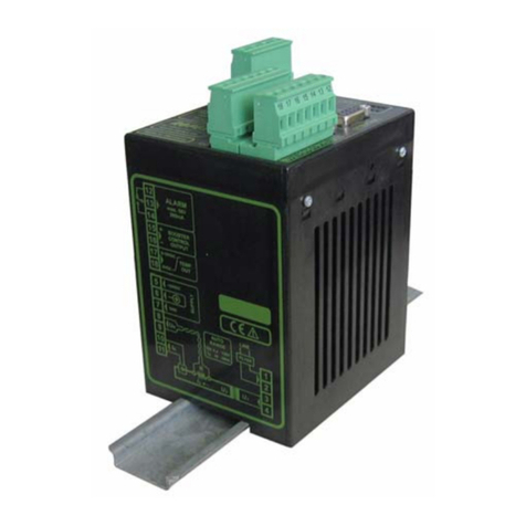
Intellitec ELECTROINC CLIMATE CONTROL User manual

1 53-22130A100
131 EISENHOWER LANE NORTH
LOMBARD, ILLINOIS 60148-5413
630-268-0010 / 1-800-251-2408
SERVICE MANUAL
INTELLITEC
PRODUCT DESCRIPTION
TheELECTRONIC CLIMATE CONTROL (ECC)Systemoffersautomaticandmanualcontrolofthe front and
rear roof-top air conditioners and furnace/s in the motorhome. The system includes an energy management
system that shuts off the air conditioners when necessary to prevent electrical over load. It also includes a
numberof featuresthatprovide theownerwith the mostcomfortable temperature controlledenvironment
possible.
In the HEAT mode the system offers automatic control of the furnace/s in a manner identical to standard wall
mountthermostats.
Ineither theLOW COOL or HIGH COOLmodestheairconditionerfans runcontinuously atthe selectedspeed
andthe compressorsare controlledtomaintain theset pointtemperature. Whenin the AUTO mode,theunit
automatically controls the compressors and selects the appropriate air conditioner fan speed based on the
differencebetween the set pointtemperatureand the ambient temperatureinthe motorhome.
In addition to controlling the temperature within the coach, the system constantly monitors the current being
drawnby all of the 120 VAC electrical appliances, including the air conditioners, and will controltheoperation
of the air conditioners to prevent them from over-loading the circuit breakers. Once the system turns the air
conditionersoff, it will keep them off until there is enough poweravailableto restore normal operation.
Thesystem has been designed tooperatefrom 120 VAC, 30 Ampservice
only
. Connectingthe coach to any
other power source will cause the system to operate improperly. If only 20 Amp service is available, “load
management” must be done manually by the owner, and only
one
air conditioner can be operated at a time,
unless the auxiliary generator is utilized.
ELECTRONIC CLIMATE CONTROL

2 53-22130A100
131 EISENHOWER LANE NORTH
LOMBARD, ILLINOIS 60148-5413
630-268-0010 / 1-800-251-2408
ELECTRONIC CLIMATE CONTROL
INTELLITEC
HOW IT WORKS
The System contains two major components, the ECC Thermostat and the ECC Control Module, along with
additionalexternalsensorswhichareconnectedto these modules.
THE ECC THERMOSTAT:
The Thermostat allows the owner to set the front and rear air conditioning and heating systems' modes and
temperatures. The electronics in this panel measure ambient temperatures via two external temperature
probes (front and rear). Based on the mode and set point temperature settings, the probes send appropriate
controlsignals to the ECC Control Module. These signalsaresent via a two wire multiplexed communication
linklabelled IPXSIGand IPXGND.
Thereare two identical sets of controls on the panel, one for each ofthe front and rear systems. The potenti-
ometers allow the user to select a desired temperature for each system in the range of 50 to 90 degrees
Fahrenheit. Moving the controls down, lowers the set point temperature. The two seven-position function
switches are used to select the furnace's and air conditioners' operating modes. A brief description of each
mode is as follows:
HEAT - TheThermostatcontrols thefurnace/sto maintainthedesired temperatureinthe coach. The
furnace/swill be energizedat an ambienttemperature2 degrees belowthe set pointtempera
ture and shut off when the ambient temperature is at the set point temperature.
Load shedding is not active in this mode.
OFF - All control settings are disabled and the Thermostat is placed in a low current “sleep”
modein order to minimize battery drain. (35-45 mA)
LOW FAN - The air conditioner fan is energized on low speed. Load shedding is active.

3 53-22130A100
131 EISENHOWER LANE NORTH
LOMBARD, ILLINOIS 60148-5413
630-268-0010 / 1-800-251-2408
ELECTRONIC CLIMATE CONTROL
INTELLITEC
HIGH FAN - Theair conditioner fan is energized on high speed. Load shedding is active.
LOW COOL - The air conditioner fan is energized on lowspeed. Theair conditioner compressor is
turnedonwhen the ambienttemperaturegoes2degrees abovethesetpointtemperature and
shutsoff when the ambient temperature reaches the set point temperature.
Loadshedding is active.
HIGH COOL - Theair conditioner fan is energized onhighspeed. The air conditioner compressor isturned
onwhen the ambienttemperatureis 2 degreesabovethe set point temperatureand shuts off
whenthe ambient temperature reaches the set point temperature. Load shedding is active.
AUTO COOL - Boththeair conditioner compressor andhighfan are on whentheambient temperature goes
5degrees above the setpointtemperature. When the ambient temperaturedropsto within 3
degrees of the set point, the fan switches to low speed. When the temperature drops to set
pointthe compressorturns off. Whenthe ambienttemperature drops2degrees belowthe set
point, the fan turns off. As the ambient temperature rises,thereverseprocedure happens.
Loadshedding is active.
INDICATORLIGHTS:
There are two indicator lights on the control panel for each of the front and rear systems. The green ON
indicator will be lit when the associated function switch is in
any
mode except the OFF mode and the system
has not shed the associated air conditioner compressor or fan. The red SHED indicator will be lit when the
associated function switch is in any mode except the OFF mode and the system has shed the associated air
conditioner compressoror fan. The ON and SHED indicatorswill blink alternately when the systemis holding
offoperation of the air conditioner compressor during the 2 minute
"
short-cycle"protection cycle.
(
seeECC ControlModule
)
THEECCTEMPERATUREPROBES:
TheseTemperature Probes arethermistors mountedinprotective plastichousings so
they can sense the temperature of the air without being influenced by the mounting
surfacetemperature. Thermistors vary their electrical resistance
inversely
with
temperature; thatis, thehigherthe temperaturethelower the thermistors'resistance.
Thethermistors utilized in this system have aresistanceof about 10,000 Ohms at 77
degrees.
Thereare two temperature probes, one for each of the front and rear systems. They
arelocated remotelyfrom the thermostatpanel to sensetemperatures inthefront and
rear. Theconnections to theECC Thermostatare via small2 pinconnectors labelled J1(FRT)andJ4 (REAR).
Since the devices are not polarity sensitive, the two wires leading to them can be reversed without harm.
However, it is necessary to connect the front and rear TEMPERATURE PROBE to the correct connector to
ensurethe ECC Thermostat interprets the correct ambienttemperaturesassociated with the front and rear of
the coach.

4 53-22130A100
131 EISENHOWER LANE NORTH
LOMBARD, ILLINOIS 60148-5413
630-268-0010 / 1-800-251-2408
ELECTRONIC CLIMATE CONTROL
INTELLITEC
THEECCCONTROLMODULE:
TheControl Module performsthe timing, sequencing,switching,and load sheddingfunctions for thefurnace/s
andair conditionerfans and compressors. Itis often locatedunder therefrigerator. Thecircuitry in thismodule
decodes the control signals sent to it via the multiplexed communication link from the ECC Thermostat.
TheControl Module operates the furnace/s by closing a set of relay contacts. The relay contacts for the front
furnaceare connected to pins 1 and 2 of connector J4, andthecontacts for the rear furnace are connected to
pins4 and5 ofthesame connector. They areelectricallyisolated fromall othercircuitryon theControl Module.
Thecontacts are functionally equivalent tothecontacts on a wall mountedthermostatand, as such, are wired
to the blue and black thermostat leads from each furnace. The coach may be equipped with one or two
furnaces. Oncoaches equippedwith one furnace,the furnace shouldbe wiredtopins 1and 2 ofconnector J4.
The pigtail connector supplied with the system (PC4) utilizes the following color codes:
PC4
/J4
pin FUNCTION COLOR
1FRONT FURNACE THERMOSTAT (BLUE) WHT/BLUE
2FRONT FURNACE THERMOSTAT (BLACK) WHT/BLK
3KEYED - NOT CONNECTED
4REAR FURNACE THERMOSTAT (BLACK) BLK
5REAR FURNACE THERMOSTAT (BLUE) BLU

5 53-22130A100
The Control Module operates the air conditioner compressors and fans via three relays with 12 VDC coils
suppliedby theA/C manufacturer andmounted in theirequipment. The contactsonthese relaysare internally
wired by the A/C manufacturer to the 120 VAC supply line for each unit and connect the compressor and the
low or high speed taps on the fan motor to that supply line when operated. The wiring between the Control
Module and these relays is low voltage (12 VDC) wiring. The Control Module uses
high side switching
to
operate the corresponding relays. One side of each of the relay coils is connected together. This "common"
leadisconnectedtogroundthrough theControl Moduleand
shouldnot
begroundedanywhereelse. Theother
sideofeachofthecoils isbrought outto oneof threeseparate leads. Theseleads areconnected tothe Control
Moduleviaa fourpin connector- J2for thefront A/Cunit, andJ3 forthe rearA/C unit. Thecorrespondingpigtail
connectors, PC2 and PC3, are supplied with the system. PC3, the rear A/C connector, is marked in red in
orderto differentiate it from PC2. The following table indicates the connection and control states:
MODULE PIGTAIL
CONN WIRE FUNCTION “ON” “OFF”
PIN COLOR VOLTAGE VOLTAGE
J2-1 BLU COMMON < 1 VDC < 1 VDC
J2-2 GRY LOWFAN +12VDC < 1 VDC
J2-3 GRN HIGHFAN +12VDC < 1 VDC
J2-4 YEL COMPRESSOR +12 VDC < 1 VDC
J3-1 BLU COMMON <1 VDC < 1 VDC
J3-2 GRY LOWFAN +12VDC < 1 VDC
J3-3 GRN HIGHFAN +12VDC < 1 VDC
J3-4 YEL COMPRESSOR +12 VDC < 1 VDC
NOTE: ThePC2 and PC3 pigtail wire colors are included for reference onlytoidentify the functions of
thewires emanating from the Control Module. The wirecolorsemanating from the front and rear
A/C units may or may not agree with these colors. Always refer to the installation manual
supplied with the A/C unit, or see “Identifying control lead functions on the A/C unit”, in order to
match the wire color/functions with those on the Control Module.
TEST SWITCH:
TheControl Module incorporatesa three positiontestswitch located betweenJ2 and J3toverify proper wiring
to each A/C unit relay. Sliding the test switch towards the J2 operates the front compressor and high fan by
connecting J2-3 and J2-4 to +12V. Sliding the test switch towards the J3 operates the rear compressor and
highfan byconnecting J2-3 andJ2-4 to+12V. Thetest switchmustbe placedin the CENTER orOFF position
fornormaloperation.
SHORTINDICATOR:
The12 volt wires feeding theairconditioners are protected from shortcircuits. Ifany of these wires is shorted
toground, the SHORT INDICATOR LED willbe illuminated, indicating the short. To help locate the short, the
plugsfeeding the air conditionersshouldbe unplugged, one atatime, to see whichcableis at fault. When the
shorted cable is unplugged, the SHORT INDICATOR will go out and the other air conditioner will operate
normally. The individual wires of the shorted plug can be tested for shorts to find which one is at fault.
131 EISENHOWER LANE NORTH
LOMBARD, ILLINOIS 60148-5413
630-268-0010 / 1-800-251-2408
ELECTRONIC CLIMATE CONTROL
INTELLITEC

6 53-22130A100
131 EISENHOWER LANE NORTH
LOMBARD, ILLINOIS 60148-5413
630-268-0010 / 1-800-251-2408
ELECTRONIC CLIMATE CONTROL
INTELLITEC
TheSHORT INDICATOR operatesin the OFF and TEST modes of the TEST SWITCH.
The Control Module also includes protection circuitry to eliminate the possibility of “short-cycling” the A/C
compressors. Short-cyclingcauses unduestress onthecompressor motorwhen refrigerantpressuresare not
allowed to stabilized prior to restarting the compressor. A two minute timer is incorporated in each of the
controlsystems for thefrontand rear A/Ccompressors. Thetimer is started eachtime one of threeconditions
is encountered: 1) If the Control Module shuts down the associated A/C compressor during a the shedding
sequence,or ifthe ambienttemperature hasreached thesetpoint. 2) Ifthe 120VACline currentsensed bythe
Current Sensor goes below 1 Amp. This will occur during an interruption of power, if the generator is not
running,or if theshorepower cord isnotplugged in. 3) If +12VDC power is notapplied to the ControlModule.
TheControl Moduledoes notallowthe compressorto bere-energizeduntil thetwo minuteperiodhas elapsed.
If during this period, the coach requires cooling or if the unit is recovering from load shedding, the Control
Module will signal the ECC Thermostat to alternately flash the ON and SHED indicators on the control panel
until the period has elapsed. After the two minute period has elapsed the system will return to normal
operation.
An important feature included in the Control Module circuitry is the Automatic Load Shedding function. This
circuitrymeasures the total current being drawn byallof the 120 VAC operated equipment in the coach being
fedthrough the main panel. The Current Sensor is mounted in the mainpaneland supplies an input signal to
theControl Module. When enough 120 volt appliances are operated so that the current exceeds 30 Amps for
more than approximately 3 seconds, the Control Module begins to shed (shut off) the A/C compressors and
fans to bring the current back below the 30 Amp limit. This prevents nuisance tripping of the main 30 Amp
breaker. The shedding sequence occurs inthe following order:
1. RearA/C compressor (if running)
2. FrontA/C compressor (if running)
3. RearA/C fan (if running)
4. Front A/C fan
When the Control Module sheds any of the loads, it returns a signal to the ECC Thermostat to light the
correspondingfront or rearSHED indicator. Basedonthe shedding sequence,the rear SHED lightwill always
be the first to light. If enough appliances are operated to generate a load current of 30 Amps, the Control
Modulewill proceed through the entire shedding sequence and essentially shut down both A/C compressors
andfans. (It isimportant tonote thatif theControlModule hasshed allfour loadsand thelinecurrent continues
to exceed the 30 Amp limit, it is likely that the 30 Amp line breaker will open.)
ALTERNATINGOPERATION:
If the total current being drawn is such that only one A/C can operate, and the ECC Thermostat continues to
demandthat both A/C compressors operate, the ControlModulewill alternate operation of the front andrear
A/C compressors every 30 minutes. When the line current is low enough to allow operation of both air
conditioners,the Control Modulewillrestore their operationina reverse order tothe shedding sequence. The
front or rear SHED indicators on the ECC Thermostat will remain lit until the corresponding A/C compressor
andfan are restoredtonormal operation.

7 53-22130A100
131 EISENHOWER LANE NORTH
LOMBARD, ILLINOIS 60148-5413
630-268-0010 / 1-800-251-2408
ELECTRONIC CLIMATE CONTROL
INTELLITEC
SYSTEMINTERCONNECTS:
12VDC power is supplied to the Control Module via connector J1. This connector also provides the signal
connectionsbetween the Control Module and ECC Thermostat,andthe Current Sensor. ConnectorPC1B is
part of the Current Sensor assembly. The pigtail connector, PC1A, is supplied with the system and is wired
perthe following table:
J1 PC1B FUNCTION COLOR
pin pin
1 1 CURRENTSENSORIN WHT
2 2 CURRENTSENSORGND WHT
J1 PC1A FUNCTION COLOR
pin pin
3 1 KEYED-NOTCONNECTED
4 2 +12 VDC POWER RED
5 3 KEYED-NOTCONNECTED
6 4 POWERGROUND BLK
7 5 IPXGND BRN
8 6 IPXSIG YEL
THEECCCURRENTSENSOR:
TheCurrent Sensoris atransformer whichconverts theACcurrent passingthrough its
core into a corresponding voltage. A functional Current Sensor has a resistance of
approximately 40 Ohms and produces an AC voltage of 0.1 VAC per Amp of current
passingthroughthecore(10Amps=1.0VAC). TheCurrentSensorshouldbemounted
in one of the knockouts in the 120 VAC box so that the donut shaped head is inside
thebox. The blackwire feedingthe30 Ampmain breakerinthe 120VAC panel should
passthrough the hole in the Current Sensor.

8 53-22130A100
131 EISENHOWER LANE NORTH
LOMBARD, ILLINOIS 60148-5413
630-268-0010 / 1-800-251-2408
ELECTRONIC CLIMATE CONTROL
INTELLITEC
USE OF THE ECC WITH AUXILIARY GENERATOR SETS
USEWITH 4KWGENERATOR
In systems using 4KW generator sets the main system includes a manual or automatic change-over which
selectsthe30 Amppower feedfrom eitherthe shorepower orgenerator. InthissituationallECCloadshedding
featureswill remainunchanged.

9 53-22130A100
131 EISENHOWER LANE NORTH
LOMBARD, ILLINOIS 60148-5413
630-268-0010 / 1-800-251-2408
ELECTRONIC CLIMATE CONTROL
INTELLITEC
USEWITH 5 KW GENERATOR
Insystems using 5 KW generator sets, anadditionalchange-over or transfer relay is used totransferthe load
of the larger A/C system (usually the front system) to the generator’s second output to utilize generator's full
output capability. In this situation the ECC load shedding features will remain unchanged, but the Current
Sensorwill not measure the loadcurrentgoing to the larger (front)A/Csystem when the generator is running.
Ifthe measured load currents through the current sensor continue to exceed 30 Ampswith the smaller (rear)
A/C system shed, the ECC Control Module will shed the larger (front) A/C system to prevent over load of the
generator.

10 53-22130A100
131 EISENHOWER LANE NORTH
LOMBARD, ILLINOIS 60148-5413
630-268-0010 / 1-800-251-2408
ELECTRONIC CLIMATE CONTROL
INTELLITEC
Trouble Shooting
If the following problems occur, proceed with their analysis in the order in which the steps are listed.
I. No green "ON" indicator on, Thermostat in any functional position.
A. Slide the test switch on the Control Module towards J2. Front compressor and high fan should
turn on. If not:
1. Make sure that the power connector (PC1A) is plugged into J1 on the control module.
Make sure that the pigtail keying matches connector keying.
2. Checkthe 5A fuse in the distribution panel for Control Module power.
3. Check for +12VDC at pin 4 of J1 on control module and ground at pin 6.
B. Check the IPX SIG and IPX GND connections to the ECC Thermostat. If OK:
1. Measurethe DC voltage between the IPX SIGandIPX GND lugs and measure the voltage
betweenpins 7 and 8 of J1 on the Control Module. The voltage should readgreater than
4 VDC and be the same at both locations. If the voltage is OK at both locations replace the
Thermostat. Ifnot:
(a) Check the wiring.
(b) Replace the Control.
II. "ON" indicator is on but the position of the set point temperature controls on the ECC
Thermostat have no effect on heat and cool functions on either front or rear systems. In
the HEAT mode the furnace stays on all the time. In the COOL modes the fan comes on
but the A/C compressor never comes on.
A. Check the installation of the Temp probes. The front probe should be connected to J1 and the
rear probe to J4 on the Thermostat. If OK, measure the resistance of the Temp Probe at the
connector. Resistance should be 7,500 to 15,000 Ohms. If not:
1. ReplaceTemp Probe.
2. ReplaceECC Thermostat.

11 53-22130A100
131 EISENHOWER LANE NORTH
LOMBARD, ILLINOIS 60148-5413
630-268-0010 / 1-800-251-2408
ELECTRONIC CLIMATE CONTROL
INTELLITEC
Trouble Shooting
III. "ON" indicator is on but the A/C compressor never comes on in either the LOW COOL,
HIGH COOL or AUTO COOL mode, even when the set point control is set to its lowest (cool)
position. In the HEAT mode, the furnace works properly in conjunction with the set
point control.
A. Slide the test switch on the Control Module towards J2. Front compressor and high fan should
turn on. If not:
1. Check to make sure that the leads on PC2 are connected to their corresponding function
at the front A/C unit. The wire colors may or may not match. It is likely that the "common"
and"high fan" leads are reversed.
2. Check the continuity of the "Comp Relay" lead between the Control Module and the front
A/C unit.
B. Slide the test switch on the Control Module towards J3. Rear compressor and high fan should
turn on. If not:
1. Check to make sure that the leads on PC3 are connected to their corresponding function at
the rear A/C unit. The wire colors may or may not match. It is likely that the "common"
and "highfan"leadsarereversed.
2. Check the continuity of the "Comp Relay" lead between the Control Module and the rear
A/C unit.
C. Check to make sure that the connector, PC1B, from the Current Sensor is plugged into J1 pins
1 and 2 and that the 120 VAC supply lead to the 30 Amp breaker in the distribution panel
passes through the hole in the Current Sensor. If OK then:
1. Unplug the Current Sensor from the Control Module and measure the resistance across the
leads to the Current Sensor. The resistance should be approximately 40 Ohms. If not:
a. Replacethe Current Sensor.

12 53-22130A100
131 EISENHOWER LANE NORTH
LOMBARD, ILLINOIS 60148-5413
630-268-0010 / 1-800-251-2408
ELECTRONIC CLIMATE CONTROL
INTELLITEC
Trouble Shooting
IV. "ON" indicator is on but fans do not operate in LOW FAN or HIGH FAN modes.
A. Make sure that the coach is plugged in to a "live" shore power outlet.
B. Check the 120 VAC circuit breakers in the distribution panel.
C. Slide test switch on Control Module towards J2. Front compressor and high fan should turn on.
IfOK replace Control Module. If not:
1. Checkwiring between PC2 and front A/C unit.
D. Slide test switch on Control Module towards J3. Rear compressor and high fan should sturn on.
IfOK,replace Control Module. If not:
1. Checkwiring between PC3 and rear A/C unit.
V. "ON" indicator is on but the furnace does not operate in HEAT mode at any thermostat
setting.
A. Checkthe fuse or circuit breaker feedingthefurnace.
B. Move the set point control up to the highest and down to the lowest temperature settings.
Somewhere in between these settings an audible click should be heard from the relay in the
control module. If not:
1. Replacethe Control Module.
C. Disconnectplug PC4 from the Control Module. Placing a shorting jumper between PC4 pins
1 and 2 should cause the front furnace to energize. Placing a shorting jumper between
PC4 pins 4 and 5 should cause the rear furnace to energize. If not:
1. Checkthe wiring between PC4 andthefurnace.
VI. "SHED" indicator is on in the HEAT mode.
A. This occurs normally within 20 seconds of system power-up. If the shed indicator stays on
and a test of the rest of the system functions checks OK, replace the Thermostat.

13 53-22130A100
131 EISENHOWER LANE NORTH
LOMBARD, ILLINOIS 60148-5413
630-268-0010 / 1-800-251-2408
ELECTRONIC CLIMATE CONTROL
INTELLITEC
Trouble Shooting
VII. "SHED" indicator is on in the FAN or COOL modes.
A. Current draw is above 30 Amps. Remove 120 VAC appliance loads from the line by turning
off all of the breakers in the distribution panel other than the 30 Amp main and A/C breakers.
If the "SHED" indicator still stays on replace the Control Module.
VIII."ON" and "SHED" indicators flash alternately in any of the COOL modes.
A. This occurs normally within a two minute period after the following situations:
1. Shore power is plugged in.
2. Generator is started and shore power is not plugged in.
3. The +12 volt power to the control module is first applied.
4. The Control Module has shed an A/C compressor because line current has exceeded
30 Amps. If the indicators continue to flash after the two minute period, replace the
ControlModule.
IX. "ON" indicator is on, air conditioners won't function properly, SHORT Indicator LED on
Control Module is "ON".
A. One or more of the wires to the air conditioner/s are shorted to ground.
1.Unplug either air conditioner connector (J2 or J3) from Control Module to seeif the SHORT
indicator goes out. The other air conditioner should operate normally.
2. Check individual wires of suspect connector, for short to ground.
3. Repair short in wires.

14 53-22130A100
131 EISENHOWER LANE NORTH
LOMBARD, ILLINOIS 60148-5413
630-268-0010 / 1-800-251-2408
ELECTRONIC CLIMATE CONTROL
INTELLITEC

15 53-22130A100
ELECTRONIC CLIMATE CONTROL
131 EISENHOWER LANE NORTH
LOMBARD, ILLINOIS 60148-5413
630-268-0010 / 1-800-251-2408
INTELLITEC
NEW SYSTEM PART NUMBERS
Intellitec Fleetwood
Part Description Part No. Part No.
Single Furnace Thermostat 00-00597-100 F80-0026
Dual Furnace Thermostat 00-00597-000 F80-0025
Control Module 00-00591-100 F97-0051
(11K/13.5K BTU air conditioner)
Control Module 00-00591-000 F97-0052
(11K/11K BTU air conditioner)
Current Sensor 01-00233-000 F93-2000
Temp Sensors (2) 00-00569-000 F93-2021
Temp Probe Cables (2) 11-00417-031 F07-9711
Change-Over 00-00331-000 F97-0060
Wiring Harness Kit 11-00375-000 F07-0150
This manual suits for next models
1
Table of contents
Popular Temperature Controllers manuals by other brands

Stork
Stork ST 501 Series manual
Elotech
Elotech R4000 Description and operating manual
NetzHome
NetzHome WT14 quick start guide
MULTISPAN
MULTISPAN UTC-121P operating manual
Gammaflux
Gammaflux TTC Advanced Setup/Troubleshooting
Greystone Energy Systems
Greystone Energy Systems HATSAP Series installation instructions
