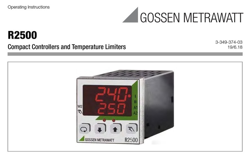
Gossen MetraWatt R2700 User manual

Interface Description
R2700 / R2500
Bus Interfaces 3-349-375-03
7/2.12

2GMC-I Messtechnik GmbH
Table of Contents
Page
1 RS 485-Bus ...................................................................... 3
1.1 Interface Configuration ...................................................................3
1.2 Communication Protocol ................................................................3
1.3 Primary Function ...........................................................................3
1.4 Time Response ..............................................................................3
1.5 Connecting the Bus Interface ..........................................................4
2 Modbus Protocol .............................................................. 4
2.1 Frame Types and Layout ................................................................4
2.1.1 Basic Layout ..................................................................................4
2.1.2 Waiting Time .................................................................................4
2.1.3 Function Code ...............................................................................4
2.1.4 Data .............................................................................................5
2.1.5 Error Check ...................................................................................5
2.1.6 Support Frames .............................................................................6
2.1.7 Error Handling ...............................................................................8
2.2 Reading and Writing Data ...............................................................8
2.2.1 Addressing ....................................................................................8
2.2.2 Format ..........................................................................................8
2.2.3 Writing Parameters ........................................................................8
2.2.4 Reading Parameters ......................................................................9
3HB-THERM
Protocol ..................................................... 10
3.1 Frame Layout ..............................................................................10
3.1.1 Basic Layout ................................................................................10
3.1.2 Formats ......................................................................................10
3.2 Message Contents .......................................................................11
3.2.1 Setpoint and Actual Value, Status (41h) ........................................11
3.2.2 Control Commands, Responses ....................................................11
3.2.3 Reading Parameters (51h) ............................................................12
3.2.4 Writing Parameters (61h) .............................................................12
3.3 Examples ....................................................................................13
3.3.1 Example for Setpoint and Actual Value ..........................................13
3.3.2 Example for Writing Parameters ....................................................13
4 Profibus DP Interface ..................................................... 14
4.1 General .......................................................................................14
4.1.1 Connection ..................................................................................14
4.1.2 Interface Configuration .................................................................14
4.1.3 Communication Protocol ..............................................................14
4.1.4 DDBF GMC_059D.gsd .................................................................14
4.1.5 Data Exchange ............................................................................14
4.2 Quick Exchange of Setpoints and Actual Values .............................15
4.3 Exchange of Measured Values, Parameters and Configurations ......15
4.3.1 Function Field ..............................................................................16
4.3.2 Block number ..............................................................................16
4.3.3 Checksum ...................................................................................16
4.3.4 Data Block Format .......................................................................16
4.3.5 Predefined Blocks ........................................................................17
4.3.6 Transmission of Parameter Sets ...................................................21
5 R2500 / R2700 Data and Parameters with the Associated
Word Addresses ............................................................. 22

GMC-I Messtechnik GmbH 3
1 RS 485-Bus
1.1 Interface Configuration
The controller with designation F1 and/or E1 is equipped with serial interfaces with the following configurations:
1.2 Communication Protocol
• If the Modbus protocol is utilized for communication between the field control level and the device level, the RTU mode and
conformity class 0 (read and write words) are used.
•TheHB-THERM
protocol has been expanded relative to document O8099-D0105 from HB-THERM.
• The communication protocol for the RS 485 interface can be configured to DIN 19244E in order to replace an R2600 or an R0217
with an R2700.
1.3 Primary Function
A master-slave interface is used with a permanently assigned master (master computer) and up to 255 slaves (devices).
Communication takes place in the half-duplex operating mode, i.e. a device connected to the master computer only becomes active
(responds):
• If it receives a valid frame addressed to itself
• If the specified maximum response delay time (t rd) has elapsed, allowing the master computer enough time to become ready to
receive
The master computer may not become active again until:
• It receives a valid response frame from the addressed device and the specified waiting period after completion of the response
frame (t rw) has elapsed
• The specified maximum response delay time (t rd) has elapsed
• The specified character delay time has elapsed (t cdt = pause between 2 character transmissions). This waiting time also applies for
the receipt of invalid and incomplete responses!
1.4 Time Response
Ready to transmit / receive after power-up t rdy approx. 5 s
Character delay time (device) t cdt < 3.5 t ch (2 ms at 19.2 kbd)
Character delay time (master, Modbus / HB-THERM) t cdm < 3.5 t ch (2 ms at 19.2 kbd) / < 50 ms
Response delay time (device) t rd 10 ... 100 ms
Query waiting time after response (master) t rw > 10 ms
Figure 1:Basic Time Response
Character time = time for transmitting one character t ch 0.57 ms at 19.2 kbd
Parameter RS 485, (2-wire) Infrared
Baud rate 9600 or 19,200 baud (adjustable) 19,200 baud
Data format 8 data bits, 1 parity bit, 1 stop bit 8 data bits, 1 parity bit, 1 stop bit
Parity Even Even
Protocol Adjustable Modbus
t rdy
Approx.
5 s
Master
Tran sm it s
Device
Responds
Master
Transmit s
t rd t cdt t rw t cdm
10 ...
100 ms
< 3.5 t ch > 10 ms < 3.5 t ch / < 50 ms
Time

4GMC-I Messtechnik GmbH
1.5 Connecting the Bus Interface
Up to 32 devices (R2700, R2500 and others) can be connected to the bus if the RS 485 interface is used. All terminals, A, B and C, are
connected to each other in parallel to this end. Wiring must be executed from device to device – devices may not be star-connected.
In the case of long bus lines (longer than 5 meters) the bus should be terminated with characteristic wave impedance at both ends (e.g.
200 between A and B).
If the W&T #86201 interface converter is used at the master, the following connector pin assignments apply to the 9-pin D-sub plug
connector: A = 1 + 2, B = 6 + 7, C = 5
2 Modbus Protocol
2.1 Frame Types and Layout
2.1.1 Basic Layout
2.1.2 Waiting Time
• Waiting time is equal to the time it would take to transmit 4 characters.
• Waiting time serves to delineate the beginning and the end of the frame, because no explicit length specification is included in the
frame.
• A frame is considered finished when waiting time has expired.
• If, for any reason, transmission of a frame is interrupted for a period which exceeds waiting time, the frame is considered finished.
The first character after the interruption is interpreted as the first character of a new frame (both parts of the frame are rejected due
to error check failures for this reason).
2.1.3 Function Code
The following function codes (FC) are supported:
Number of
Characters
Meaning Comment
1 Slave address (0 to 255) Device address (not 0)
0 = to all (only where function code = 5, 16)
1 Function code See section 2.1.3 on page 4
n Data See section 2.1.4 on page 5 and section 2.1.6 on page 6.
1 Error check (CRC-16) low byte See section 2.1.5 on page 5
1 Error check (CRC-16) high byte
(4) Waiting time, no characters are transmitted See section 2.1.2 on page 4
Function Code Meaning Applications
3 Read words For reading values and parameters
5 Write single bit Only for resetting the device
7 Read status Query: “device OK”
16 Write words For writing parameters
A
B
C
Master
21
20
19
R2700
8
9
10
R2500
20
21
19
R2600
82
81
88
R0217

GMC-I Messtechnik GmbH 5
2.1.4 Data
Refer to section 2.1.6 on page 6 and section 2.2 on page 8 for details concerning the data field in the frame.
• Data used with Modbus are always 16 bit words.
The high byte is transmitted first.
• Numeric values are represented as compliments of 2.
• Quantities with a 7 bit format are expanded to 15 bit.
• Bit fields in 8 bit format are expanded with a high byte = 0.
2.1.5 Error Check
Correct transmission of the frame is assured by means of the CRC-16 cyclical redundancy check. Both CRC-16 characters are
generated as follows based upon all of the characters included in the frame (slave address to last data byte):
1 Presetting of a 16 bit register (CRC-16 register) with FFFFh
2 Exclusive OR linking of the low bytes in the CRC-16 register to the frame’s character,
results to CRC-16 register
3 Shift the CRC-16 register one bit to the right;
A 0 is added and the displaced least significant bit (LSB) is saved.
4 Where LSB = 0, continue as of step 5.
Where LSB = 1, establish exclusive OR linking of the CRC-16 registers to A001h.
5 Repeat steps 3 and 4 until a total of 8 shifts to the right have occurred.
At this point, one of the frame’s characters has been processed.
6 Execute steps 2 through 5 for each of the frame’s remaining characters.
7 The content of the CRC-16 register, preceded by the low byte, is added to the frame after all of the frame’s characters have been
processed.
For example, programming in C would result in the following code:
/* ------------------------------------------------------------------
crc_16() calculate the crc_16 error check field
Input parameters: buffer: string to calculate CRC
length: bytes number of the string
Return value: CRC value.
------------------------------------------------------------------ */
unsigned int crc_16 (unsigned char *buffer, unsigned int length) {
unsigned int i, j, lsb, tmp, crc = 0xFFFF;
for ( i = 0; i < length; i++ ) {
tmp = (unsigned char) *buffer++;
crc ^= tmp;
for ( j = 0; j < 8; j++ ) {
lsb = crc & 0x0001;
crc >>= 1;
if ( lsb != 0 ) crc ^= 0xA001;
}
}
return (crc);
}

6GMC-I Messtechnik GmbH
2.1.6 Support Frames
Read Words (FC = 3)
Query from Master:
Response from Slave:
If the word address does not exist in the controller, or if the number of words is too great, the controller transmits an “error response”
with corresponding error code (see also section 2.1.7 on page 8).
Reset (FC = 5)
Query from Master:
Response from Slave:
Transmission of a request to all slaves is possible (slave address = 0).
The “write single bit function” is used exclusively for restarting the device.
If the bit address is not 0, or if it is not deleted, the controller transmits an “error response” with corresponding error code (see also
section 2.1.7 on page 8).
Character No. Meaning
1 Slave address (not 0)
2FC=3
3 Word address (high byte)
4 Word address (low byte)
5 Number of words (high byte)
6 Number of words (low byte)
7 CRC-16 (low byte)
8 CRC-16 (high byte)
Character No. Meaning
1Slaveaddress
2FC=3
3 Number of characters (n)
4 Word data (n/2 words)
... Respective high byte first
... ...
4 + n CRC-16 (low byte)
5 + n CRC-16 (high byte)
Character No. Meaning
1Slaveaddress
2FC=5
3 Bit address (high byte) = 0
4 Bit address (low byte) = 0
5 Bit data (high byte) = 0
6 Bit data (low byte) = 0
7 CRC-16 (low byte)
8 CRC-16 (high byte)
Not possible

GMC-I Messtechnik GmbH 7
Query: “Device OK” (FC = 7)
Query from Master:
Response from Slave:
Bit 4 is set in the status if no write tasks are currently possible (FC = 16).
Bit 5 is set if an error has occurred (operator prompt, read error status).
Other bits are set to 0.
Write Words (FC = 16)
Request from Master:
Response from Slave:
Transmission of a request to all slaves is possible (slave address = 0), in which case no response ensues from the slaves.
If the word address does not exist in the controller, if the number of words is too great or if the contained data is invalid, the controller
transmits an “error response” with corresponding error code (see also section 2.1.7 on page 8).
Character No. Meaning
1 Slave address (not 0)
2FC=7
3 CRC-16 (low byte)
4 CRC-16 (high byte)
Character No. Meaning
1Slaveaddress
2FC=7
3 Status
4 CRC-16 (low byte)
5 CRC-16 (high byte)
Character No. Meaning
1Slaveaddress
2FC=16
3 Word address (high byte)
4 Word address (low byte)
5 Number of words (high byte)
6 Number of words (low byte)
7 Number of characters (n)
8 Word data (n/2 words)
... Respective high byte first
... ...
8 + n CRC-16 (low byte)
9 + n CRC-16 (high byte)
Character No. Meaning
1 Slave address (not 0)
2FC=16
3 Word address (high byte)
4 Word address (low byte)
5 Number of words (high byte)
6 Number of words (low byte)
7 CRC-16 (low byte)
8 CRC-16 (high byte)

8GMC-I Messtechnik GmbH
2.1.7 Error Handling
If the slave address does not exist, if a parity error has occurred, if the error check fails (CRC-16 false) or if the function code is not
supported, the slave does not send a response.
If the controller is incapable of executing the request although the frame is formally correct, it generates an error response in whose
error code (character 3) the reason for non-execution is specified.
The error response is recognized by the fact that the most significant bit is set in the returned function code.
Error Response Error Code
2.2 Reading and Writing Data
2.2.1 Addressing
All controller setting parameters and data are assigned to parameters groups according to functional relationships. Together with
cyclical data (measured values) and events data (errors and alarms), the controller can thus be operated entirely via the bus interface.
A complete list of all parameters and data is included in section 5 on page 22.
2.2.2 Format
Data are transferred in the same format in which they appear at the device display.
Temperature quantities are formatted depending upon configuration in tenths of a degree of full degrees, in C or F.
2.2.3 Writing Parameters
Example:
Set the setpoint for the device with address 3 to 200C.
Request from Master (7 bit quantities are expanded to 15 bit):
Response from Slave (if no error has occurred)
Character No. Meaning Value Meaning
1 Slave address (not 0) 2 Impermissible address
2 FC + 80h 3 Impermissible data content
3 Error code 6 Currently no write tasks possible
4 CRC-16 (low byte) 9 Number of words is too great
5 CRC-16 (high byte) 10 Writing impermissible
Character No. Value Meaning
1 03h Device address
2 10h Function code = write words
3 00h Word address (high byte)
4 00h Word address (low byte)
5 00h
6 01h Number of words = 1
7 02h Number of characters = 2
8 00h
9 C8h Setpoint
10 BEh
12 A6h CRC-16
Character No. Value Meaning
1 03h Device address
2 10h Function code = write words
3 00h Word address (high byte)
4 00h Word address (low byte)
5 00h
6 01h Number of words = 1
7 00h
8 2Bh CRC-16

GMC-I Messtechnik GmbH 9
2.2.4 Reading Parameters
Example:
Read in cyclical data from the device with address 3.
Query from Master
Response from Slave (if no error has occurred)
Character No. Value Meaning
1 03h Device address
2 03h Function code = read words
3 B0h Word address (high byte)
4 00h Word address (low byte)
5 00h
6 05h Number of words = 5
7A2h
8 EBh CRC-16
Character No. Value Meaning
1 03h Device address
2 03h Function code = read words
3 0Ah Number of characters = 2 times 5
4 00h
5 B7h Actual value: 183C
6 00h
7 00h No measured value available
8 00h
9 64h Manipulated variable: 100% heat
10 00h
12 00h No measured current value available
12 00h
14 1Ch Cold junction temperature: 28C
15 40h
15 02h CRC-16

10 GMC-I Messtechnik GmbH
3HB-THERM
Protocol
3.1 Frame Layout
3.1.1 Basic Layout
To a great extent the protocol is compatible with the R6000.
3.1.2 Formats
Pseudo ASCII
Block length, checksum and parameters are transmitted on a hexadecimal basis. The hexadecimal numbers are converted to ASCII,
and all numbers greater than 9 (A ... F) are represented as 3Ah ... 3Fh. Negative quantities are represented as compliments of 2
(e.g. -100 3Fh, 3Fh, 39h, 3Ch).
BCD
Temperature setpoint and actual value are transmitted in message 41h in BCD format.
Negative quantities are preceded by a minus sign. e.g. -100 2Dh, 31h, 30h, 30h)
Character
No.
Content Comment Format Value Range
1 Address Device address 1 ... 79 30h + address B1h ... FFh
31h ... 7Fh
2 ... 4 Block length Binary number of bytes in the entire frame 3-place pseudo ASCII 3 x 30h ... 3Fh
5 Type of message Target data, actual dataSee section 3.2.1 Binary 41h
Trigger reset, device is restarted
Empty message
Binary 44h
Clear all errors, stored channel and device errors are deleted
Empty messages
Binary 49h
Read parametersSee section 3.2.3 Binary 51h
Write parametersSee section 3.2.4 Binary 61h
Parameters cannot be written, response in case of invalid value or if flash is
active
Empty message
Binary 69h
Message not understood, response in case of incorrect block length,
message type or checksum
Empty message
Binary 7Fh
6 ... n Message Setpoint, actual value, manipulated variable
Status
Parameters index
Parameters
Or empty
4-place BCD
Binary
2-place pseudo ASCII
4-place pseudo ASCII
2Dh, 30h ... 39h
00h ... 7Fh
2 x 30h ... 3Fh
4 x 30h ... 3Fh
n+1, n+2 Checksum Low byte of the sum of all characters 2-place pseudo ASCII 2 x 30h ... 3Fh

GMC-I Messtechnik GmbH 11
3.2 Message Contents
3.2.1 Setpoint and Actual Value, Status (41h)
Master Transmission (machine device, block length: 14)
Slave Response (device machine, block length: 19)
*Deviates from original protocol, e.g. extended
3.2.2 Control Commands, Responses
The controller’s conditions (response) are unambiguous in the HB-THERMprotocol, and are unambiguously switched by means of
the control commands.
The R2500 / R2700 can have several conditions at the same time – in combinations which are practical or necessary (e.g. controller on
+ start-up + self-tuning).
Six conditions are combined for hot-runner control (controller function bits, PI = 20h):
controller on, manual mode, self-tuning on, start-up activated, reduction (setpoint swapping) and boosting.
xset
— not set
?Any
Character No. Content Comment Value
6 ... 9 Setpoint in 0.1° C -99.9° C ...
999.9° C
2Dh, 39h, 39h, 39h ...
39h, 39h, 39h, 39h
10 Reserve 60h
12 Control command See section 3.2.2 “B” ... “t” (42h ... 74h)
12 Reserve 20h
Character No. Content Comment Value
6 ... 9 Actual value in 0.1° C -99.9° C ...
999.9° C
2Dh, 39h, 39h, 39h ...
39h, 39h, 39h, 39h
10 ... 13 Manipulated variable in % -100 ...
100
2Dh, 31h, 30h, 30h ...
30h, 31h, 30h, 30h
15 Status word Bit 0 Remote = machine
Bit 1 Sensor = internal
Bit 2 Received impermissible setpoint
Bit 3 Reserve
Bit 4 Group alarm (without channel alarms)1
Bits 5, 6 and 7Fixed code
0
1
0 / 1
0
0 / 1
1, 1, 0
15 Alarm 1 Low byte, channel error status (PI = 21h)*
16 Alarm 2 High byte, channel error status (PI = 21h)*
17 Response Control commandSee section 3.2.2* “B” ... “t” (42h ... 74h)
Control Command, Response p m r o t b R O T B
Controlleron —xxxxxxxxx
Manualoperation ? x ————————
Start-up ? ? ————x x x x
Self-tuning ———x ———x ——
Reduction (setpoint swapping) ? ? — — x — — — x —
Boost ? ? ———x ———x

12 GMC-I Messtechnik GmbH
3.2.3 Reading Parameters (51h)
All parameter of a given type, i.e. from the same parameters index, are transmitted together in the R2500 / R2700. There is no access
to individual words.
As opposed to the Modbus protocol, all temperature values are transmitted in tenths of a degree Celsius, regardless of configuration.
Master Transmission (machine device, block length: 9)
Slave Response (device machine, block length: 13 ... 89)
3.2.4 Writing Parameters (61h)
For addressing and contents see section 3.2.3 on page 12
Master Transmission (machine device, block length: 13 ... 89)
Slave Response (device machine, block length: 7)
• After the parameters have been accepted, the device responds with 61h and an empty message.
• If a parameter value is impermissible, or if the memory cannot be accessed at the moment, the device responds with 69h and an
empty message.
Character No. Content Comment Value
6 ... 7 Parameters Index See section 5 30h, 30h ... 3Ah, 30h
Character No. Content Comment Value
6 ... 7 Parameters Index See section 5 30h, 30h ... 3Ah, 30h
8 ...
7 + 4 x n
n parameters n times 4-place pseudo ASCII n times
30h, 30h, 30h, 30h ...
3Fh, 3Fh, 3Fh, 3Fh
Character No. Content Comment Value
6 ... 7 Parameters Index See section 5 30h, 30h ... 3Ah, 30h
8 ...
7 + 4 x n
n parameters n times 4-place pseudo ASCII n times
30h, 30h, 30h, 30h ...
3Fh, 3Fh, 3Fh, 3Fh

GMC-I Messtechnik GmbH 13
3.3 Examples
3.3.1 Example for Setpoint and Actual Value
Data exchange, 1st channel at device 1
Setpoint data: Setpoint 95 °C Actual value data: Actual value 95 °C
Command Control Manipulated variable 23%
Error None
Response Control
Machine Transmission:
Device Response:
3.3.2 Example for Writing Parameters
Upper limit value 1 of the device with address 3 is set to 10 °C.
Machine transmission:
Device response:
B1h Address = B0h + device address
30h, 30h, 3Eh Block length = 14
41h Setpoint code, command
30h, 39h, 35h, 30h Setpoint: 95.0° C
60h Reserve
72h control
33h, 30h Checksum = 330h
31h Address = 30h + device address
30h, 31h, 33h Block length = 19
41h Actual value code, status
30h, 39h, 35h, 30h Actual value: 95.0 °C
30h, 30h, 32h, 33h Manipulated variable: 23%
62h Status
00h, 00h No channel alarms
72h control
36h, 3Dh Checksum = (3)6Dh
B3h Address = B0h + device address
30h, 32h, 39h Block length = 41
61h Code = write parameters
30h, 31h Parameters index = 01h
30h, 30h, 36h, 34h 0064h = 100 corresponds to 10.0°
3Dh, 3Ah Checksum = 2DAh
3h Address = 30h + device address
30h, 30h, 37h Block length = 7
61h Code = write parameters, request executed
32h, 3Bh Checksum = 12Bh

14 GMC-I Messtechnik GmbH
4 Profibus DP Interface
4.1 General
4.1.1 Connection
4.1.2 Interface Configuration
• The R2700 is equipped with an RS 485 serial interface per EN 50170 ( Profibus DP) for communication with a master computer, an
SPC etc. Baud rates of up to 12 Mbit per second are supported.
• The user address for Profibus operation is selected during configuration. User address changes do not become effective until the
device has been switched off and then back on again.
• Address selection via the Profibus “SetSlaveAdress” function is not supported.
4.1.3 Communication Protocol
The data transmission protocol per EN 50170 is used for communication between the field control level and the device level.
4.1.4 DDBF GMC_059D.gsd
The file required for configuring the Profibus DP (DDBF multi-channel Profibus DP) can be downloaded free of charge from the GMC-I
Messtechnik GmbH website (http://www.gossenmetrawatt.com). It’s identical to the file for the R6000.
4.1.5 Data Exchange
Data exchange is similar to the process used for the R355, i.e. the HTBs can be used in consideration of Profibus connection for
combination with R355 or R6000.
Basic Layout of Output Data in the Data_Exchange Send Frame (Profibus master R2700)
Basic Layout of Input Data in the Data_Exchange Response Frame (R2700 Profibus master)
R2700 Terminal Designation 9-Pin Subminiature
Plug Connector
19 DGND C 5
20 RxD/TxD-P B 3
21 RxD/TxD-N A 8
Addr. Offset Contents Configura-
tion
Contents
0 FF 8 bit Function field
1 BL 8 bit Block number
2, 3 CS 16 bit Checksum
4 ... 11 Data
12 ,13 SP 15 Bit Setpoint
14, 15 16 bit Security code: 55AAh
16 ... 27 Unused
Addr. Offset Contents Configura-
tion
Contents
0 FF 8 bit Function field
1 BL 8 bit Block number
2, 3 CS 16 bit Checksum
4 ... 11 Data
12 ,13 PV 15 Bit
Actual value (controlled variable)
14, 15 ED 15 Bit Manipulated variable in %
16 ... 27 Unused

GMC-I Messtechnik GmbH 15
4.2 Quick Exchange of Setpoints and Actual Values
The command variable (setpoint) is transmitted to the R2700 in the peripheral output word with address offset 12. The command
variable is only accepted by the controller if security code 55AAh is pending in the output word with offset address 14; and the value
lies within the setpoint limits.
The controlled variable (actual value) and the manipulated variable are specified as a percentage (%) in the peripheral input words with
addresses 12 and 14. Updating takes place every 100 ms commensurate with the sampling cycle.
4.3 Exchange of Measured Values, Parameters and Configurations
In order to exchange large volumes of data in a targeted fashion, the first two addresses (function field and block number) are used to
control transmission.
Data are only accepted or delivered if the write or read request (toggle bits) is written.
Data Exchange Profibus Master R2700
Data Exchange R2700 Profibus Master
General
• The quantities are selected using block numbers.
Each block includes 4 quantities (values, parameters or configurations).
The quantities are in 16 bit format (with some exceptions).
• During the read operation, the R2700 offers the newest data blocks available for reading.
• Recall of data to be written works in the same way as the write operation, and the write request is set in the function field (bit 2 = 1).
• Communication is initiated by writing to the FFh block. Time and a command word are written.
The controller then transmits the parameter set ID and the device variant (block FFh).
If the command word is set to 100h, all of the channels’ parameters which are permitted to communicate then follow, so that the
data blocks receive the controller’s settings.
Addr. Offset Con-
tents
Config-
uration
Contents
0 FF 8 bit Function field
1 BL 8 bit Block number
2, 3 CS 16 bit Word checksum via addr. offset 0, 4 ... 10
4 ... 11 Data to be written
Addr. Offset Con-
tents
Config-
uration
Contents
0 FF 8 bit Function field
1 BL 8 bit Block number
2, 3 CS 16 bit Word checksum via addr. offset 0, 4 ... 10
4 ... 11 Read data

16 GMC-I Messtechnik GmbH
4.3.1 Function Field
The function field controls the read and write operations. The R2700 only responds at the moment the read or write toggle bit is
changed. This means that the block number and the data always have to be written first, and finally the function field.
Function Field (addr. offset 0)Profibus Master R2700
Function Field (addr. offset 0)R2700 Profibus Master
4.3.2 Block number
• The content of the blocks to be written is predefined (see also section 4.3.5).
• The setting limits for the parameters are monitored during writing. If a parameter is not accepted, the “impermissible parameter”
error bit is set. This bit must be acknowledged in the error status.
4.3.3 Checksum
In order to assure correct transmission, the word checksum (EXOR operation) of peripheral words 0, 4, 6, 8 and 10 is inserted into the
peripheral word with offset 2. If the checksum is incorrect, the acknowledge bit is cleared by the respectively receiving page without
changing the toggle bit.
4.3.4 Data Block Format
Each of the quantities to be transmitted is transmitted in one word (16 bit). The order depends on the respective parameters index (PI).
Bit Function Value Meaning
0, 1 FC
Function code
0
1
2, 3
No function
Data Exchange
Reserved
2 Request 0 / 1 1 = read request instead of write request
3 — 0 / 1 Not used
4 Acknowledge 0 / 1 1 = data to be read accepted
5 — 0 / 1 Not used
6 S toggle 0 / 1 When the status changes, new data to be written are pending.
7 L toggle acknowledgment 0 / 1 If the same status is set as in the peripheral input and the acknowledge bit, the
read data have been accepted. At the same time, this is a request for the
R2700 to generate new data to be read.
Bit Function Value Meaning
0, 1 FC
Function code
0
1
2, 3
No function
Data Exchange
Reserved
2 Request 0 / 1 Same value as Profibus Master -> R2700
3 — 0 / 1 Not used
4 Acknowledge 0 / 1 1 = data to be written accepted
0 = data to be written not accepted, no S toggle acknowledgement
5 — 0 / 1 Not used
6 S toggle acknowledgement 0 / 1 If status is the same as in the peripheral output, the data have been accepted
by the R2700.
7 S toggle 0 / 1 When the status changes, new data to be read are pending at the R2700.
Config-
uration
Interpretation Value Range MSB
8 bit Bit field, positive
number
0 ... 255 0
± 7 bits Number –128 ... 127 Expanded with plus or
minus sign
16 bit Bit field (0 ... 65535) —
± 15
bits
Number –32768 ... 32767 —
BCD 2 BCD numbers 2 times 0 ... 99 —

GMC-I Messtechnik GmbH 17
4.3.5 Predefined Blocks
The word addresses of the corresponding data blocks for the S7 project are specified in the address columns.
Channel Blocks
• Blocks 10 and 11 are only read. Block 10 is updated at each channel every 100 ms.
Block 11 is only updated when its content changes, and at the beginning of communication.
• Block 14 is transmitted independently after self-tuning has been completed. The handling blocks should take this into
consideration, so that ascertained values are not overwritten.
• The same applies to block 17, which contains the nominal heating current value after triggering automatic ascertainment of the
nominal heating current value.
Block Ad-
dress
PI Value
Read only
10 10 B1 Momentary actual value
12 B0 Momentary manipulating factor
14 21 Error status (actual)
16 24 Controller status
11 18 20 Controller function (actual)
20 B8 Momentary setpoint
22 6C Actual heating current value
24 — —
Write
12 26 20 Controller function (setpoint)
28 00 Setpoint
30 21 Error status (acknowledgement)
32 03 Setpoint 2
13 34 28 Manual manipulating factor
36 — —
38 07 Maximum setpoint
40 06 Minimum setpoint
14 42 10 Proportional zone heating (XpI)
44 11 Proportional zone cooling (XpII)
46 14 System delay (Tu)
48 15 Cycle time
15 50 01 First upper limit value
52 02 First lower limit value
54 04 Second upper limit value
56 05 Second lower limit value
16 58 0E Setpoint ramp, up
60 0F Setpoint ramp, down
62 12 Dead band H/C
64 1F Switching hysteresis
17 66 1D Maximum manipulating factor
68 1C Minimum manipulating factor
70 18 Motor stroke time
72 60 Nominal heating current
18 74 16 Actuator manipulating factor
76 17 Actuation manipulating factor
78 19 Influencing quantity manipulating factor
80 1E Sensor error manipulating factor
19 82 08 Setpoint boosting
84 09 Boosting duration
86 0A Actuation setpoint
88 0B Dwell time during actuation
1A 90 33 Sensor type
92 0C Actual value correction
94 0D Actual value factor
96 25 Oscillation disabling
1B 98 22 Controller config.
100 — —
102 — —
104 36 Limit value configuration

18 GMC-I Messtechnik GmbH
Device Blocks
• Time is set with the FFh block.
• Read blocks 90 and 91 are only updated when their content changes, or at the beginning of communication.
Block Ad-
dress
PI Value Meaning
Read only
90 10 21 Device error status (actual)
12 — —
14 — —
16 71 Program status
91 18 B0 Measured quantity, input 1
20 B0 Measured quantity, input 2
22 24 Output status
24 B0 Reference junction temperature
Write
92 26 21 Device error status (acknowledgement)
28 32 Device Control
30 70 Program configuration
32 71 Program status
93 34 3F Parameter set ID in BCDs, min
36 3F h, d
38 3F mon, y
40 31/35 Device feature / firmware version
94 42 30 Device ID
44 35 Firmware version
46 92 Logger sampling cycle
48 93 Logger controller
95 50 64 Primary current transformer
52 68 Current monitoring threshold
54 0C Measuring range lower limit
56 0D Measuring range upper limit
96 58 37 Binary input 1
60 37 2
62 37 Switching output1
64 37 2
97 66 37 3
68 37 4
70 37 Continuous output
72 — —
98 74 10 Proportional zone heating (XpI)
76 — —
78 14 System delay (Tu)
80 15 —
99 82 — Channel error mask A1
84 — Device error mask A1
86 — Channel error mask A2
88 — Device error mask A2

GMC-I Messtechnik GmbH 19
Blocks 9Ah through 9Fh are used to transmit large volumes of data – currently for reading out the alarm history (up to 1 kB) and the
data logger (up to 30 kB).
Data to be read out are selected with the first word of block 9Ah.
The read operation is controlled with bits 0 through 3 of the second word of block 9Ah.
Write and read
9A 90 — Address
92 — Control commands
94 — Reserved
96 2E / — Device error / — From 4th entry
Read only
9B 98 2F/98 Number of entries
100 2E / — Time stamp, s/min Time stamp for the first entry,
calculated from the point in time of the last entry
(PI = 99h) for logger data.
102 2E / — Time stamp, h/d
104 2E / — Time stamp, mon/y
9C 106 2E/96 Channel error / logger data 4 entries are always transmitted
(see also section 5, PI = 2Eh or PI = 96h).
108 2E/96 Device error / logger data
110 2E/96 Time stamp / logger data
112 2E/96 Time stamp / logger data
9D 114 2E/96 Time stamp / logger data
116 2E/96 Channel error / logger data
118 2E/96 Device error / logger data
120 2E/96 Time stamp / logger data
9E 122 2E/96 Time stamp / logger data
124 2E/96 Time stamp / logger data
126 2E/96 Channel error / logger data
128 2E/96 Device error / logger data
9F 130 2E/96 Time stamp / logger data
132 2E/96 Time stamp / logger data
134 2E/96 Time stamp / logger data
136 2E/96 Channel error / logger data
3600 ... 1
–1
Logger entry to be read
Following 4 logger entries
4196 ... 4097
4095
Alarm history to be read (100 ... 1 +4096)
Following 4 entries( –1 +4096)
Bit Function Profibus Master R2700 R2700 Profibus Master
0 Read request 1 = read request 0 = read request processed
1 Read acknowledgment 0 = acknowledgment of read request 1 = requested data transmitted
2 No entry 0 = acknowledgment of read request 1 = no data to transmit
3 Incorrect address 0 = acknowledgment of read request 1 = incorrect address
Block Ad-
dress
PI Value Meaning

20 GMC-I Messtechnik GmbH
Program Blocks
• Configuration, control and status query is carried out by means of device blocks.
• The data content of blocks 32 through 39 is the content of word addresses 7300h through 731Dh (see also section 5).
Block Ad-
dress
PI Value
Read only
30 10 — —
12 — —
14 — —
16 — —
31 18 — —
20 — —
22 — —
24 — —
Write
32 26 73 Duration 1st segment
28 73 Duration 2nd segment
30 73 Duration 3nd segment
32 73 Duration 4th segment
33 34 73 Duration 5th segment
36 73 Duration 6th segment
38 73 Duration 7th segment
40 73 Duration 8th segment
34 42 73 Duration 9th segment
44 73 Duration 10th segment
46 73 Duration 11th segment
48 73 Duration 12th segment
35 50 73 Target setpoint 1st segment
52 73 Target setpoint 2nd segment
54 73 Target setpoint 3rd segment
56 73 Target setpoint 4th segment
36 58 73 Target setpoint 5th segment
60 73 Target setpoint 6th segment
62 73 Target setpoint 7th segment
64 73 Target setpoint 8th segment
37 66 73 Target setpoint 9th segment
68 73 Target setpoint 10th segment
70 73 Target setpoint 11th segment
72 73 Target setpoint 12th segment
38 74 73 Control tracks, 1st and 2nd segments
76 73 Control tracks, 3rd and 4th segments
78 73 Control tracks, 5th and 6th segments
80 73 Control tracks, 7th and 8th segments
39 82 73 Control tracks, 9th and 10th segments
84 73 Control tracks, 11th and 12th segments
86 — —
88 — —
Other manuals for R2700
1
This manual suits for next models
1
Table of contents
Other Gossen MetraWatt Temperature Controllers manuals