THORLABS TC300 User manual

TC300
Heater Temperature
Controller
User Guide

TC300 Temperature Controller
Table of Contents
Chapter 1Warning Symbol Definitions..............................................................................................1
Chapter 2Safety....................................................................................................................................2
Chapter 3Overview...............................................................................................................................3
Chapter 4Operational Elements.........................................................................................................4
4.1.Front and Rear Panel ......................................................................................................4
4.2.Hirose Connectors ..........................................................................................................5
Chapter 5Getting Started.....................................................................................................................6
5.1.Initial Setup ......................................................................................................................6
5.2.Heater Connection ..........................................................................................................6
5.3.Thermal Sensor Connection ..........................................................................................6
5.3.1.Thermistors ...........................................................................................................................6
5.3.2.Platinum Resistance Temperature Sensors .........................................................................7
5.3.3.Thermocouples .....................................................................................................................8
5.3.4.AD590 ...................................................................................................................................8
5.3.5.External Sensor Port .............................................................................................................8
5.4.Turning the TC300 On.....................................................................................................9
5.5.Front Panel Operation.....................................................................................................9
5.6.Menu Structure ..............................................................................................................10
5.7.Compatible Thorlabs Devices ...................................................................................... 11
Chapter 6Stand-Alone Operation......................................................................................................12
6.1.Operation Mode ............................................................................................................. 12
6.2.Sensor Configuration....................................................................................................13
6.2.1.Thermistors (NTC1 and NTC2) ...........................................................................................13
6.2.2.Platinum Resistance Temperature Detector (PT100 and PT1000) ....................................14
6.2.3.Thermocouple (THERMO C.)..............................................................................................15
6.2.4.AD590 .................................................................................................................................15
6.2.5.External Sensor...................................................................................................................15
6.3.Voltage/Current Limit....................................................................................................16
6.4.Temperature Range.......................................................................................................17
6.5.Enabling/Disabling Output ...........................................................................................17
6.6.PID Tuning .....................................................................................................................17
6.7.Single/Dual Channel Operation....................................................................................18
6.8.Sync Mode .....................................................................................................................19
6.9.Trigger Mode..................................................................................................................19
6.10.Analog Output ...............................................................................................................20
6.11.General Settings in Options Menu...............................................................................20
6.12.Error Handling ...............................................................................................................21
Chapter 7Software...............................................................................................................................23

TC300 Heater Temperature Controller
Chapter 8Command Line Operation.................................................................................................24
8.1.Command Line Overview .............................................................................................24
8.2.Command Lines Summary ........................................................................................... 24
8.3.Description of Commands............................................................................................30
8.3.1.IDN? – Model Number, Hardware and Firmware Version of TC300 ..................................30
8.3.2.ST? – Device Status of TC300............................................................................................30
8.3.3.EN1=n ; EN2=n – Channel status of TC300 .......................................................................30
8.3.4.TSET1=n; TSET1?; TSET2=n; TSET2=? – Target Temperature of TC300.......................31
8.3.5.TACT1?; TACT2? – Actual Temperature of TC300............................................................31
8.3.6.TMAX1=n; TMAX1?; TMAX2=n; TMAX2? – Target Temperature Max value of TC300 ....31
8.3.7.TMIN1=n; TMIN1?; TMIN2=n; TMIN2? – Target Temperature Min value of TC300 ..........31
8.3.8.VOLT1?; VOLT2? – Actual Output Voltage of TC300 ........................................................32
8.3.9.CURR1=n; CURR1?; CURR2?; CURR2=n – Output Current of TC300 ............................32
8.3.10.CMAX1=n; CMAX1?; CMAX2=n; CMAX2? – Output Current Max Value of TC300 ..........32
8.3.11.VMAX1=n; VMAX1?; VMAX2=n; VMAX2? – Output Voltage Max value of TC300 ...........33
8.3.12.CSET1?; CSET2? – Output Current Set Value of TC300 ..................................................33
8.3.13.MOD 1 =n; MOD 1?; MOD =n; MOD 2? – Test Mode of TC300 ........................................33
8.3.14.OFFSET1=n; OFFSET1?; OFFSET2=n; OFFSET2? – Sensor Offset Value of TC300.....34
8.3.15.TYPE1=n; TYPE1?; TYPE2=n; TYPE2? – Sensor Type of TC300....................................34
8.3.16.PARA1=n; PARA1?; PARA2=n; PARA2? – Sensor Parameter of TC300 .......................35
8.3.17.BETA 1=n; BETA 1?; BETA 2=n; BETA 2? – NTC Beta Value of TC300 ..........................36
8.3.18.EXTBETA1=n; EXTBETA 1?; EXTBETA 2=n; EXTBETA 2? – External Beta Value of
TC300 36
8.3.19.T0CH1=n; T0CH1?; T0CH 2=n; T0CH2? – Thermistor T0 value of TC300 .......................36
8.3.20.R0CH1=n; R0CH1?; R0CH2=n; R0CH2? – Thermistor R0 value of TC300 ......................37
8.3.21.HARTA1=n; HARTA1?; HARTB1=n; HARTB1? HARTC1=n; HARTC1? HARTA2=n;
HARTA2?; HARTB2=n; HARTB2? HARTC2=n; HARTC 2? –Thermistor Steinhart-Hart Coefficient
37
8.3.22.TRIG1=n ; TRIG1? TRIG2=n ; TRIG2?– Trigger Mode of 300...........................................38
8.3.23.BRIGHT=n; BRIGHT? – Brightness of TC300....................................................................38
8.3.24.DARK=n; DARK? – Darkness Status of TC300..................................................................39
8.3.25.KB=n; KB? – Lock Status of TC300....................................................................................39
8.3.26.KP1=n; KP1?; KP2=n; KP2? – KP Value of PID.................................................................39
8.3.27.TI1=n; TI1?; TI2=n; TI2? – TI Value of PID.........................................................................39
8.3.28.TD 1=n; TD 1?; TD 2=n; TD 2? – TD Value of PID ............................................................40
8.3.29.PERIOD1=n; PERIOD1?; PERIOD2=n; PERIOD2? – PERIOD Value of PID ...................40
8.3.30.PID1DEF!; PID2DEF! – Load Default PID Parameters ......................................................40
8.3.31.QUIET=n; QUIET? – Quiet Status of TC300 ......................................................................41
8.3.32.CHANNELS=n; CHANNELS? – Channel Count of TC300.................................................41
8.3.33.COPYPARA – Copy CH1 Parameters to CH2....................................................................41
8.3.34.TSINK? – Heatsink Temperature of TC300 ........................................................................41
8.3.35.TAMB? – Ambient Temperature of TC300 .........................................................................41
8.3.36.SN? – Serial Number of TC300 ..........................................................................................41
8.3.37.MONITOR? – Monitor Messages of TC300........................................................................42
8.3.38.ERR? – Error Status of TC300............................................................................................42
8.3.39.WARN? – Warning Status of TC300...................................................................................43
8.3.40.LOADFACT! – Restore the Device Factory Parameters ....................................................43
Chapter 9Maintenance........................................................................................................................44
9.1.Fuse Replacement.........................................................................................................44
9.2.Firmware Update ...........................................................................................................44
Chapter 10Mechanical Drawing...........................................................................................................46
Chapter 11Specifications.....................................................................................................................47
TC300 Temperature Controller
Chapter 12Regulatory...........................................................................................................................48
12.1.FCC Declarations of Conformity..................................................................................49
12.2.CE Declarations of Conformity ....................................................................................50
Chapter 13Thorlabs Worldwide Contacts..........................................................................................51


TC300 Heater Temperature Controller Chapter 1: Warning Symbol Definitions
Rev B, January 5, 2022 Page 1
Chapter 1 Warning Symbol Definitions
Below is a list of warning symbols you may encounter in this manual or on your device.
Symbol Description
Direct Current
Alternating Current
Both Direct and Alternating Current
Earth Ground Terminal
Protective Conductor Terminal
Frame or Chassis Terminal
Equipotentiality
On (Supply)
Off (Supply)
In Position of a Bi-Stable Push Control
Out Position of a Bi-Stable Push Control
Caution: Risk of Electric Shock
Caution: Hot Surface
Caution: Risk of Danger
Warning: Laser Radiation
Caution: Spinning Blades May Cause Harm

TC300 Heater Temperature Controller Chapter 2: Safety
Page 2 CTN017856-D02
Chapter 2 Safety
All statements regarding safety of operation and technical data in this instruction manual will only apply when the
unit is operated correctly.
SHOCK WARNING
HIGH VOLTAGE INSIDE
To avoid electrical shock, the power cord protective grounding conductor must be connected to
ground. Do not operate without cover installed. Refer servicing to qualified personnel.
ATTENTION
Do not obstruct the air ventilation slots in the housing.
WARNING
For all applications, use an IEC320 compatible power cord fitted with a plug appropriate for your
particular power socket. Make sure that the line voltage rating marked on the rear panel agrees with
your local power supply and that the appropriate fuses are installed. Changing the main fuse can be
done by the user. Apart from this fuse, there are no user-serviceable parts in this product.
ATTENTION
This unit must not be operated in explosive environments.
!
!!
!

TC300 Heater Temperature Controller Chapter 3: Overview
Rev B, January 5, 2022 Page 3
Chapter 3 Overview
The TC300 Heater Temperature Controller is a dual channel controller intended for use with resistive heating
elements. It is equipped with two channels, each with a driving capability up to 48 W, capable of either independent
or synchronized operation. This general-purpose instrument can drive various types of heaters, including foil and
resistor types. It accepts feedback from various type of temperature sensors including resistive temperature sensor
and thermal couples (AD590). Each channel has programmable P, I, and D gains. A user-programmable maximum
temperature limit provides protection to the device being overheated, and a user-programmable current/voltage
limit protects the heating element from being over driven.
Capable of stand-alone operation from a simple keypad interface, the TC300 can also be controlled with a PC using
a standard USB Type B connector and our TC300 Application Program. Interfacing with a PC can also be achieved
with a simple command-line interface from any terminal window.
Contents of Package
Each TC300 is shipped with the following standard accessories:
• A flash drive containing software and a user guide
• Regional power cord
• USB Standard B Cable

TC300 Heater Temperature Controller Chapter 4: Operational Elements
Page 4 CTN017856-D02
Chapter 4 Operational Elements
4.1. Front and Rear Panel
Figure 1 TC300 Front and Rear Panel
1. LCD Screen – When the device is switched on, the main user interface is display on the LCD.
2. Adjustment Knob – The knob can be used to navigate the user interface and change values.
3. Power Switch – Turns the unit on and off.
4. Keypads – Used to navigate the user interface.
5. Enable/Disable Button for Channel 1 - This button enables/disables Channel 1. The button is equipped
with a built-in LED indicator which lights on when Channel 1 is enabled and off when Channel 1 is disabled
6. 6-pin Hirose Connector for Channel 1 - For detailed pin assignment see Chapter 4.2.
7. Enable/Disable Button for Channel 2 - This button enables/disables Channel 2. The button is equipped
with a built-in LED indicator which lights on when Channel 2 is enabled and off when Channel 2 is disabled.
8. 6-pin Hirose Connector for Channel 2 - For detailed pin assignment see Chapter 4.2.
9. Analog Output of Channel 1 (ANLG1) - 0 to + 5 V output proportional to the actual temperature of Channel
1; 0 V corresponds to the minimum temperature setting and + 5 V corresponds to the maximum temperature
setting of Channel 1.
10. AC Input Connector
11. Trigger of Channel 1 (TRIG1) - When set to input: high level (+5 V) input will enable Channel 1, and low
level (0 V) input will disable it. When set to output: outputs high level (+5 V) when Channel 1 is enabled and
outputs low level (0 V) when Channel 1 is disabled.
12. USB Type B Connector – For software and command line operation. For more details, see Chapter 7 and
Chapter 8.
5
6
7
8
1
2
3
4
9
10
11
12
13
14
15
16

TC300 Heater Temperature Controller Chapter 4: Operational Elements
Rev B, January 5, 2022 Page 5
13. Analog Output of Channel 2 (ANLG2): 0 to + 5 V output proportional to the actual temperature of Channel
2; 0 V corresponds to the minimum temperature setting and + 5 V corresponds to the maximum temperature
setting of Channel 2.
14. Cooling Fan
15. Trigger of Channel 2 (TRIG) - When set to input: high level (+5 V) input will enable Channel 2, and low
level (0 V) input will disable it. When set to output: outputs high level (+5 V) when Channel 2 is enabled and
outputs low level (0 V) when Channel 2 is disabled.
16. Mono Jack Socket for External Sensor
4.2. Hirose Connectors
On the front panel of the TC300, there are two 6-pin Hirose connectors. Each corresponds to an operation channel
of the TC300. The two connectors allow users to wire the heaters and various type of sensors to the TC300 for
temperature control operation. The detailed pin assignment is show below.
Pin No. Definition
Pin 1 Heater Output +
Pin 2 Heater Output -
Pin 3 Sensor + (4-Wire PT100/PT1000 only)
Pin 4 Sensor +
Pin 5 Sensor -
Pin 6 Sensor - (4-Wire PT100/PT1000 only)
Figure 2 Hirose Connector Pin Assignment

TC300 Heater Temperature Controller Chapter 5: Getting Started
Page 6 CTN017856-D02
Chapter 5 Getting Started
5.1. Initial Setup
Set the device on a benchtop. Make sure the device is switched off and the power cord is disconnected. All wiring
and configuration should be done before the unit is powered on.
5.2. Heater Connection
Most resistive heaters do not have a polarity, so simply wire the heater to pin 1 (Output Heater +) and pin 2 (Output
Heater -) of the Hirose connector on the front panel, as shown in Figure 3. The TC300 is compatible with most
resistive heaters but can achieve maximum efficiency when paired with heaters with 12 resistance.
Figure 3 Heater Connection
5.3. Thermal Sensor Connection
The TC300 is compatible with a variety of different types of temperature sensors including:
Thermistors
Platinum Resistance Temperature Sensors
Thermocouples
AD590
Each one requires a slightly different wiring and set up.
5.3.1. Thermistors
The TC300 is compatible with thermistors with resistance ranging up to 999 k. Most thermistors do not have a
polarity. To connect a thermistor to the TC300, simply wire the thermistor to pin 4 (Sensor +) and pin 5 (Sensor -)
of the Hirose connector as shown in Figure 4.
Figure 4 Thermistor Connection

TC300 Heater Temperature Controller Chapter 5: Getting Started
Rev B, January 5, 2022 Page 7
5.3.2. Platinum Resistance Temperature Sensors
The TC300 is compatible with both 100 (PT100) and 1000 (PT1000) platinum resistance temperature sensors.
Both 2-wire and 4-wire connections are supported.
A 2-wrie platinum resistance temperature sensor usually does not have a polarity. To connect a 2-wire, simply wire
the sensor to pin 4 (Sensor +) and pin 5 (Sensor -) of the Hirose connector, as shown in Figure 5.
Figure 5 2-Wire Platinum Sensor Connection
However, as the actual resistance of platinum sensors are relatively low, we recommend using sensors that support
4-wire connection which could alleviate the problems due to extension wire length and resistance imbalance
between the leads, providing a much more accurate measurement result.
A 4-wire platinum sensor has 4 wires divided into two color coded groups. Connect the two wires from one group
to pin 3 (Sensor + 4 Wire PT100/PT1000 only) and pin 4 (Sensor +) and connect the other two wires from the other
group to pin 5 (Sensor -) and pin 6 (Sensor - 4 Wire PT100/PT1000 only), as shown in Figure 6.
Figure 6 4-Wire Platinum Sensor Connection
3-wire platinum sensors are not supported by the TC300.

TC300 Heater Temperature Controller Chapter 5: Getting Started
Page 8 CTN017856-D02
5.3.3. Thermocouples
Thermocouples are usually polarized. To connect a thermocouple to the TC300, wire the positive lead to pin 4
(Sensor +), and the negative lead to pin 5 (Sensor -), as seen in Figure 7.
Figure 7 Thermocouple Connection
5.3.4. AD590
The TC300 also supports the AD590 temperature transducer. To connect an AD590 to the TC300, wire the positive
lead (anode) to pin 4 (Sensor +), and the negative lead (cathode) to pin 5 (Sensor -), as seen in Figure 8.
Figure 8 AD590 Connection
5.3.5. External Sensor Port
The TC300 also allows the user to connect a thermistor type of temperature via the “EXT. SENSOR” port on the
back panel. The EXT.SENSOR port accepts a 2.5 mm stereo earphone jack. It is directly compatible with the
Thorlabs TSP-TH temperature probe sensor.
Figure 9 External Sensor Connection

TC300 Heater Temperature Controller Chapter 5: Getting Started
Rev B, January 5, 2022 Page 9
It is also possible for users to utilize the EXT. SENSOR port with
third-party thermistors. Users would need to have
a cable with a 2.5 mm stereo earphone jack on one end and an open lead at the other. Wire the thermistor in
between the two leads corresponding to the TH+ and TH- contact of the 2.5mm stereo jack (as shown in Figure 10).
The TC300 can support thermistors with resistance up to 999 k.
Figure 10 EXT. SENSOR Connector (2.5 mm Stereo Earphone Jack)
5.4. Turning the TC300 On
Once both the heater and the thermistor are corrected connected, the unit is ready to be powered on. Connect the
power line to the AC inlet on the back panel with the included power cord and press the rocker switch on the front
panel to turn on the device.
The device will take a few second to initialize and then it will enter the HOME screen.
SHOCK WARNING
HIGH VOLTAGE INSIDE
To avoid electrical shock, the power cord protective grounding conductor must be connected to
ground. Do not operate without cover installed. Refer servicing to qualified personnel.
5.5. Front Panel Operation
Use the three buttons beneath the LCD to interact with the TC300. Press the “UP” and “DOWN” buttons to move
the cursor on the screen. Press the “ENTER” button to confirm or cancel selection. When a value is selected, the
color of the text will become yellow. Pressing the “UP” button will then increase the value and pressing the “DOWN”
button will decrease the value. Once the change to a value is done, press “ENTER” again to validate the change.
Figure 11 Front Panel Operation of TC300
Alternatively, the knob above the power switch can also be used to navigate the user interface and make changes
to values. Turning the knob clockwise will move the cursor on the screen downwards and turning the knob
UP Button:
Move Cursor Up
Decrease Value
Clockwise:
Move Cursor Down
Increase Value
Counterclockwise:
Move Cursor Up
Decrease Value
DOWN Button:
Move Cursor Down
Increase Value
ENTER button:
Confirm Selection
Cancel Selection

TC300 Heater Temperature Controller Chapter 5: Getting Started
Page 10 CTN017856-D02
counterclockwise will move the cursor upwards. When a value is selected by pressing the “ENTER” button, turn the
knob clockwise to increase and counterclockwise to decrease the value.
When in the HOME screen, move the cursor to the “MENU” icon on top of the main screen and press “ENTER” to
access the menu screen.
In the menu screen, moving the cursor to the icon and pressing the “ENTER” button will enter the next menu
screen. Move the cursor to the icon and press the “ENTER” button to go back to the previous menu screen.
Move the cursor to icon and press “ENTER” to go back to the HOME screen.
Figure 12 Menu Screen
5.6. Menu Structure
The TC300 is set to single channel operation by default. When in single channel operation, only the parameters of
Channel 1 will be displayed on the HOME screen and only the settings of Channel 1 will be visible in the menus. In
the menus, there are three screens for setting the parameters of Channel 1 and one screen for making general
optional settings of the device.
Figure 13 Menu Structure in Single Channel Operation
Go to next Screen
Back to Last Screen
Go to HOME Screen
Main Screen
Menu: Options
Menu:
CH1 Settings

TC300 Heater Temperature Controller Chapter 5: Getting Started
Rev B, January 5, 2022 Page 11
When in dual channel operation, the parameters of both Channel 1 and Channel 2 will be displayed on the HOME
screen. Settings of both channels will be visible in the menus. For each channel, there are 3 screens for setting
parameters. There is one screen for making general optional settings of the device.
To enable the operation and setting of Channel 2, please see Chapter 6.7 for more details.
Figure 14 Menu Structure in Dual Channel Operation
5.7. Compatible Thorlabs Devices
The Thorlabs devices listed are compatible with TC300. Since they are all equipped with the corresponding 6-pin
Hirose connector, they support plug-and-play operation with the TC300, with no extra wiring required.
GCH25-75, Heater Assembly for Ø9, Ø19, or Ø25 mm x 75 mm Glass Cells
TLK-H, Flexible Polyimide Foil Heater with 10 kΩThermistor and 6 Pin Hirose Connector
SM1L10HR, Temperature-Controlled SM1 Lens Tube
LCC1xxxT, Temperature-Stabilized Full-Wave and Half-Wave LC Retarders
Main Screen
Menu: Options
Menu:
CH1: Settings
Menu:
CH2: Settings

TC300 Heater Temperature Controller Chapter 6: Stand-Alone Operation
Page 12 CTN017856-D02
Chapter 6 Stand-Alone Operation
6.1. Operation Mode
The TC300 supports two different operation modes, heater mode and constant current mode.
In heater mode, the TC300 works in close loop, taking temperature measurements from the temperature sensor
and adjusting the current applied to the heater automatically based on a PID algorithm to reach set target
temperature. A temperature sensor is necessary when working in heater mode.
In heater mode, the sensor type, the actual temperature, and the target temperature will be shown on the main
screen. To change the target temperature, move the cursor on to the target temperature number, press “ENTER”
button to confirm selection, and then turn the knob or press the “UP” or “DOWN” buttons to change value. Press
“ENTER” again to validate the value change.
In current mode, the TC300 works as a current source in open loop. It outputs a constant current according to user
input current value. A temperature sensor is not needed when working in current mode.
In current mode, only the target current and actual current reading will be shown on the main screen. To change
the target current, move the cursor on to the target current number, press the “ENTER” button to confirm selection,
and then turn the knob or press “UP” or “DOWN” button to change value. Press “ENTER” again to validate the value
change.
Figure 15 Main Screens for Heater and Current Mode
WARNING: HOT SURFACE
In current mode, the TC300 does not monitor the temperature on the heat load. The actual
temperature could rise to a very high level that could cause harm to the heater and become a hazard
to personnel.
To set the operation mode of the TC300, go to the first setting screen of each channel, move the cursor on “Mode
Set”, and press “ENTER” to confirm selection. Then use the knob or the “UP”/“DOWN” buttons to toggle between
“Heater” and “Current”. Press “ENTER” again to confirm selection. When current mode is selected, the settings of
the temperature sensor will not be shown on screen.
Figure 16 Toggling Between Heater and Current Mode

TC300 Heater Temperature Controller Chapter 6: Stand-Alone Operation
Rev B, January 5, 2022 Page 13
6.2. Sensor Configuration
In the first setting screen of each channel, move the cursor on “Sensor” and press “ENTER” to confirm selection,
then use the knob or “UP”/“DOWN” buttons to select the correct type of sensor. Press “ENTER” again to confirm
selection.
The sensor types below are available to be selected in the setting screen. Each sensor type has a few different
variable parameters that will be displayed on the screen beneath the sensor type accordingly.
NTC1: Thermistor whose resistance is defined by the “Beta” formula
NTC2: Thermistor whose resistance is defined by the Steinhart-Hart equation
PT100: 100 ΩPlatinum Resistance Temperature Detector
PT1000: 1000 ΩPlatinum Resistance Temperature Detector
THERMO C.: Thermocouple
AD590: Temperature Transducer AD590
EXT1: Thermistor whose resistance is defined by the “Beta” formula, connected to EXT.SENSOR port
EXT2: Thermistor whose resistance is defined by the Steinhart-Hart equation, connected to EXT.SENSOR
port
ATTENTION
The TC300 can only determine shorted or open sensor connections; it cannot determine if the
installed sensor does not match the programmed sensor selection. Care must be taken to ensure
that the settings match the actual sensor used, or damage will occur to the heating system.
6.2.1. Thermistors (NTC1 and NTC2)
When the sensor type is set to NTC1, the TC300 measures the resistance value of the thermistors wired to the
Hirose connectors on front panel and calculates the temperature based on the “Beta” formulas defined below.
𝑅𝑇𝑅
∗𝑒
Thus 𝑇𝑅
∗
∗
With: T - Temperature in K (Kelvin)
R - Thermistor resistance at temperature
β- Thermistor constant (sensitivity index, B value, Beta)
R
0
- Thermistor nominal resistance at temperature T0
T
0
- Nominal temperature (usually 298.15 K = 25° C)
The TC300 allows users to set the values of β(Beta), R
0
, and T
0
. For different thermistors, the actual value of these
parameters can vary and can usually be found on their datasheets.
Figure 17 Sensor Settings for Thermistors
!!

TC300 Heater Temperature Controller Chapter 6: Stand-Alone Operation
Page 14 CTN017856-D02
The TC300 also supports the Steinhart-Hart method to approximate the relation between temperature and
thermistor resistance when the sensor type is set to NTC2.
The Steinhart-Hart method can be described by the formula
1𝑇
⁄𝐴𝐵∗ln𝑅𝐶∗ln𝑅
with T being the temperature in K (Kelvin) and A, B, and C being the Steinhart-Hart parameters. The TC300 allows
user input of the A, B, and C parameters. For thermistors that support the Steinhart-Hart method, the actual value
of A, B, and C can usually be found on their datasheets.
6.2.2. Platinum Resistance Temperature Detector (PT100 and PT1000)
The TC300 is compatible with both the 100 Ω(PT100) and 1000 Ω(PT1000) platinum resistance temperature
detector. When working with platinum sensors, set the sensor type to PT100 or PT1000 according to the actual
sensors wired to the Hirose connectors on front panel.
The TC300 measures the resistance and calculates the temperature of the PT100 and PT1000 platinum resistance
temperature detectors using the following formula:
𝑅𝑅
1𝐴∗𝑇𝐵∗𝑇
With: A = 3.9083 x 10⁻³ °C-1
B = -5.775 x 10⁻⁷ °C-2
T - Temperature in K (Kelvin)
R - Thermistor resistance in at temperature T
R0- 100 for the PT100; 1000 for the PT1000
The TC300 supports 2-wire and 4-wire connection for both PT100 and PT1000. When the sensor type is set to
PT100 or PT1000, select the “Parameter” option to toggle between the 2-wire and 4-wire connection setting.
As the actual resistance of platinum sensors is relatively low, we recommend using sensors that support 4-wire
connection which could alleviate the problems due to extension wire length and resistance imbalance between the
leads, providing a much more accurate measurement result.
When sensor type is set to PT100 or PT1000, the TC300 also offers the option of a user input offset to allow the
device to compensate any offset in temperature measurement.
To determine the offset value, a reference temperature measurement needs to be made with a third-party
instrument. Use the platinum sensor that is already connected to the TC300 and the reference instrument to
measure the temperature of the same item at the same spot. The PT Offset value will then be:
𝑃𝑇 𝑂𝑓𝑓𝑠𝑒𝑡 𝑇 𝑇
With Treference: Temperature reading of the third-party reference instrument
TTC300: Temperature reading of the TC300 with platinum sensor
Figure 18 Sensor Settings for Platinum Sensors
3-wire platinum resistance temperature detectors are not compatible with the TC300.

TC300 Heater Temperature Controller Chapter 6: Stand-Alone Operation
Rev B, January 5, 2022 Page 15
6.2.3. Thermocouple (THERMO C.)
When working with thermocouples as temperature sensors, set the sensor type to THERMO C.
The TC300 supports both J type and K type thermocouples. Set the Parameter according to the actual type of the
sensors that are wired to the Hirose connectors on the front panel.
Figure 19 Sensor Settings for Thermocouples
6.2.4. AD590
When working with an AD590 temperature transducer, simply set the sensor type to AD590. There are no variable
parameters for the AD590.
Figure 20 Sensor Settings for AD590
6.2.5. External Sensor
When a temperature sensor is connected to the “EXT. SENSOR” port on the back panel, setting the sensor type to
EXT1 or EXT2 will allow the TC300 to take the temperature reading from the external sensor. Currently only
thermistor-type temperature sensors are supported by the “EXT. SENSOR” port.
When the sensor type is set to EXT1, the TC300 measures the resistance value of the thermistors wired to the
“EXT. SENSOR” port and calculates the temperature based on the “Beta” formulas:
𝑅𝑇𝑅
∗𝑒
thus 𝑇𝑅∗
∗
With: T - Temperature in K (Kelvin)
R – Thermistor resistance at temperature T
β- Thermistor constant (sensitivity index, B value, Beta)
R0- Thermistor nominal resistance at temperature T0
T0- Nominal temperature (usually 298.15 K = 25° C)
Table of contents
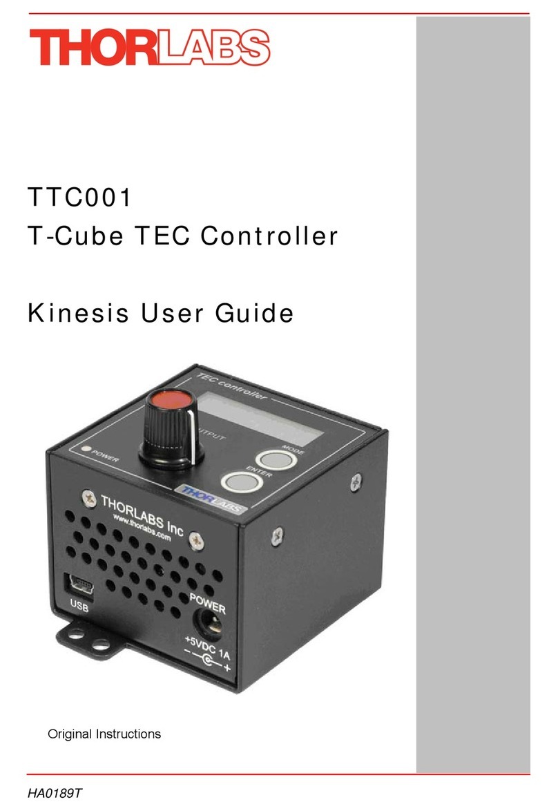
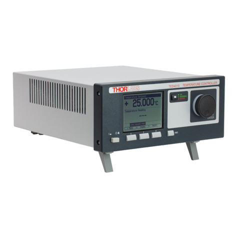
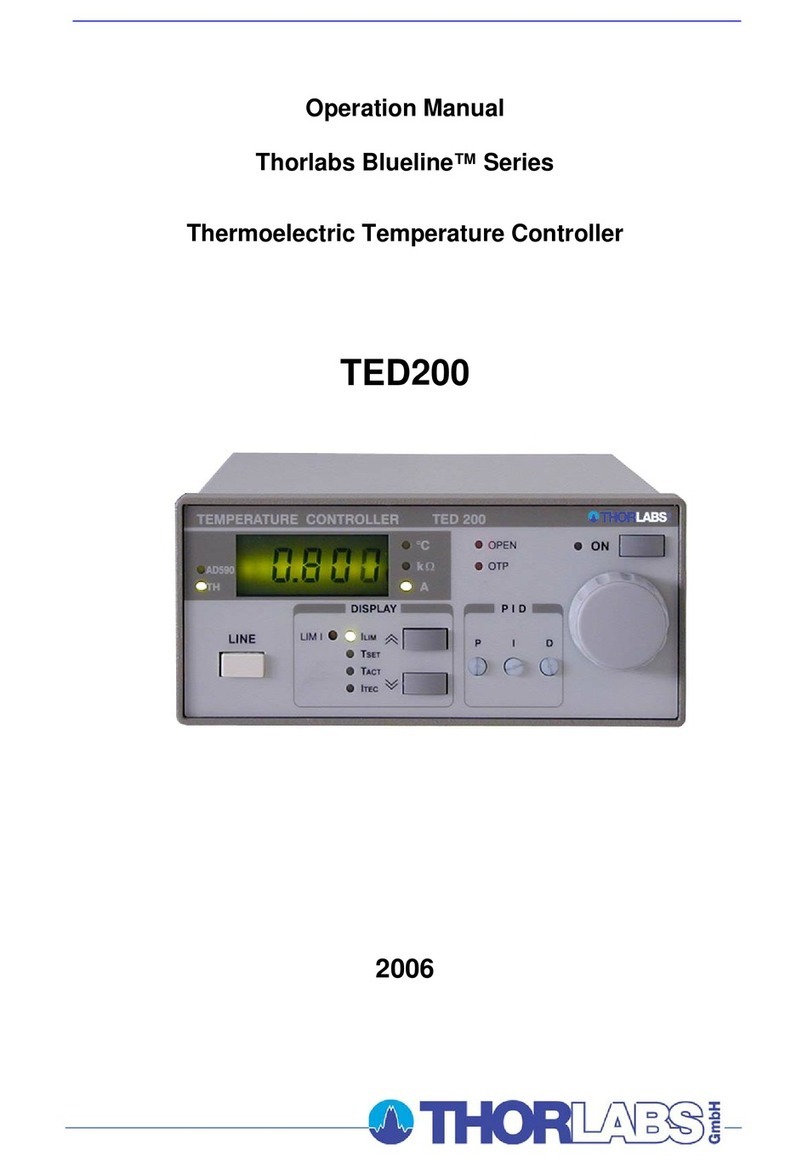
Other THORLABS Temperature Controllers manuals

THORLABS
THORLABS TCLDM9 User manual

THORLABS
THORLABS MTD415T User manual

THORLABS
THORLABS TC200 User manual

THORLABS
THORLABS TED350 User manual

THORLABS
THORLABS TXP Series User manual

THORLABS
THORLABS T-Cube TTC001 User manual

THORLABS
THORLABS TED200C User manual

THORLABS
THORLABS Blueline Series User manual

THORLABS
THORLABS ITC8000 User manual

THORLABS
THORLABS TED4015 User manual