Intenza 550GC Series User manual
Owner’s Manual
Cycle
Intenza 550GC Series Cycle Owner’s Manual ©Intenza 2020. All rights reserved.
Intenza 550GC
Intenza 550GC3
Intenza 550GC5

Table of Contents
EN
DE
FR
550GC Series Cycle Owner’s Manual
Bedienungsanleitung für das Fahrrad der 550GC—Serie
Mode d'Emploi du Modèle de Vélo 550GC
3
20
38
1

EN
2Intenza 550GC Series Cycle Handbook: Important Safety Instructions And Precautions
IMPORTANT SAFETY PRECAUTIONS
WARNING To reduce the risk of burns, fire, electric shock, or injury to persons, carefully read and adhere to the
following important precautions and information before operating the 550GC Series Cycle—
· If you have pre—existing health problems or a disability, it is recommended that you consult your physician, in order to find the
training method best suited to you. Incorrect or extensive training can result in serious health injuries.
· The manufacturer expressly assumes no responsibility for health risks, personal injury, property damage or consequential damages
sustained by or through the use of this device, unless it is a case of consequential damage which can be traced back to faulty
material and/or manufacturing, and which come under the responsibility of the manufacturer.
· This appliance is not intended for use by persons with reduced physical, sensory or mental capabilities, or lack of experience and
knowledge, unless they have been given supervision or instruction concerning use of the appliance by a person responsible for their
safety. Keep children under the age of 13 away from this machine.
· If it has been dropped or damaged, or dropped into water, return the appliance to a service center for examination and repair.
· Use this appliance only for its intended use as described in this manual. Do not use attachments not recommended by the
manufacturer.
· Never drop or insert any object into any opening.
· Do not use outdoors.
· Do not operate where aerosol (spray) products are being used or where oxygen is being administered.
· Installation of power supply shall comply with local building codes.
· SAVE THESE INSTRUCTIONS
Please use the chain to secure the front tube and the
pedal, and make sure that the crank cannot be rotated
significantly after lock the chain with the lock.

EN
550GC Series
550GC Series GC3
3
PLEASE NOTE
Intenza 550GC Series Cycle Handbook: Important Safety Instructions And Precautions
IMPORTANT SAFETY PRECAUTIONS
SAFETY PRECAUTIONS
· It is the responsibility of the owner to ensure that all users are informed of all warnings and precautions for proper use, and are
only authorised to use the bike independently after being successfully briefed by a qualified Trainer or Instructor.
· This appliance can be used by children aged from 13 years and above and persons with reduced physical, sensory or mental
capabilities or lack of experience and knowledge if they have been given supervision or instruction concerning use of the appliance
in a safe way and understand the hazards involved. Children shall not play with the appliance. Cleaning and user maintenance shall
not be made by children without supervision.
· Keep 550GC Series Cycle indoors, away from moisture and dust. Do not place 550GC Series Cycle outdoors, in a garage or covered
patio or near water or swimming pools. Operating temperature of 550GC Series Cycle must be between 15°C—40°C Celsius (59°—104°F)
at a maximum humidity of 65%.
· Always place the bike on a stable, level surface. If the bike is to be placed on a hardwood floor or carpet, it is recommended to
place a floor mat underneath the bike, to protect the floor from becoming damaged.
· The level of safety of the bike can only be guaranteed if it is regularly checked for possible damage as well as wear and tear (e.g.
fixing points, E—Brake, Pedals, toe straps, etc.). Consult an authorised service provider, or the manufacturer directly, to ensure
that regular inspections are properly carried out.
· Carry out all maintenance, care and service procedures as described in this manual on a regular basis. Defective parts must be
replaced immediately, and the equipment must not be used until the repairs have been carried out. Only use original parts from
the manufacturer. Repairs must only be carried out by the manufacturer’s authorised service technicians.
· 550GC Series must not be used by persons exceeding weight of 340 lbs/159 kg.
· Always wear appropriate close fitting cycling or athletic attire and sturdy shoes, preferably cycling—specific shoes, while operating
the bike. Unfastened shoelaces may become caught in the drive system and lead to injury.
· The bike does not have an independently—moving flywheel. The pedals will continue to move with the flywheel until the
flywheel stops. The movement can only be stopped by using the emergency brake or by reducing the pedaling frequency in a
controlled manner. Always ride with resistance load to ensure that your pedaling motion is controlled. Do not adjust handlebar
or saddle during workout. Do not pedal backwards.
· Do not attempt to remove your feet from the pedals or dismount from the machine until both the pedals, and the flywheel, have
completely stopped. Failure to follow these instructions may lead to loss of control and the potential for serious injury.
· If you feel pain or dizziness while exercising, stop immediately. It is recommended that you consult a doctor if the pain does not
subside for an extended period of time.
· Class S training equipment shall always be used in a supervised environment.
· Review of all applicable warning notices and contact dealer when replacement of worn warning labels is necessary.
EN
4
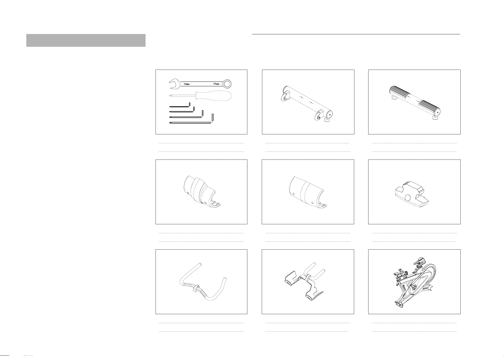
550GC Series Cycle Part List
Open the shipping carton. Remove all parts from the carton and cardboard inserts.
Before you begin assembly, verify that the following hardware items are packed with the equipment. You will require the following
to assemble the 550GC Series: 1* 2.5, 3, 5, 6 and 15mm hex wrench, and a Phillips screwdriver.
Intenza 550GC Series Cycle Handbook: 550GC Series Cycle Part List
1. 2.5, 3, 5, 6, hex wrenchs, 15mm wrench and
Phillips screwdriver (NOT INCLUDED)
2. Stabliser, front, assy
QTY 1 QTY 1
3. Stabliser, rear, assy
4. Cover, Stabiliser, front
QTY 1
5. Cover, Stabiliser, rear
QTY 1
6. Cap, end, track, HB, rear
QTY 1
7. Dipping, handlebar, rear
QTY 1
8. Dipping, handlebar, front for GC
QTY 1
9. Assy, frame, main
QTY 1

EN
5
550GC Series Cycle Part List
10. Pedal assy, L, standard 11. Pedal assy, R, standard 12. Dome screw, M8 x 15L
13. Dome screw, M4 x 10L
QTY 1 QTY 1 QTY 8
QTY 4 (GC),9 (GC3)
Intenza 550GC Series Cycle Handbook: 550GC Series Cycle Part List
14. Washer, M8
QTY 8 QTY 1
QTY 4
15. Tapping screw, M4 x 8L
16. Screw, countersunk 17. Assy, handlebar, front for GC3
QTY 1
18. Bracket, console, fixed for GC3
QTY 1

EN
6
550GC Series Cycle Part List
22. Socket Screw for GC3
QTY 3
Intenza 550GC Series Cycle Handbook: 550GC Series Cycle Part List
21. Assy, console for GC319. Cover, console—seat, front for GC3 20. Cover, console—seat, rear for GC3
QTY 1
QTY 1 QTY 1

EN
7
Intenza 550GC Series Cycle Handbook: 550GC Series Cycle Assembly Instructions
STEP 1
Assemble the front Stabliser
STEP 2
Assemble the rear Stabliser
550GC Series Cycle Assembly Instructions
STEP 4
Assemble the rear Stabliser Cover
STEP 3
Assemble the front Stabliser Cover
COMPONENTS ANDTOOLS
Dome screw, M4 x 10L (13)
COMPONENTS ANDTOOLS
Dome screw, M8 x 15L (12), Washer, M8 (14)
COMPONENTS ANDTOOLS
Dome screw, M8 x 15L (12), Washer, M8 (14)
COMPONENTS ANDTOOLS
Dome screw, M4 x 10L (13)
WARNING If there are large fluctuations in temperature,
please allow the bike to acclimatise to the surrounding
temperature before proceeding with assembly.
Ensure that bolts are tightened with significant force to
minimise loosening during use. If bolts are loosened after
initial assembly, we recommend using medium—strength
LOCTITE® 243 when reassembling.
EN
8
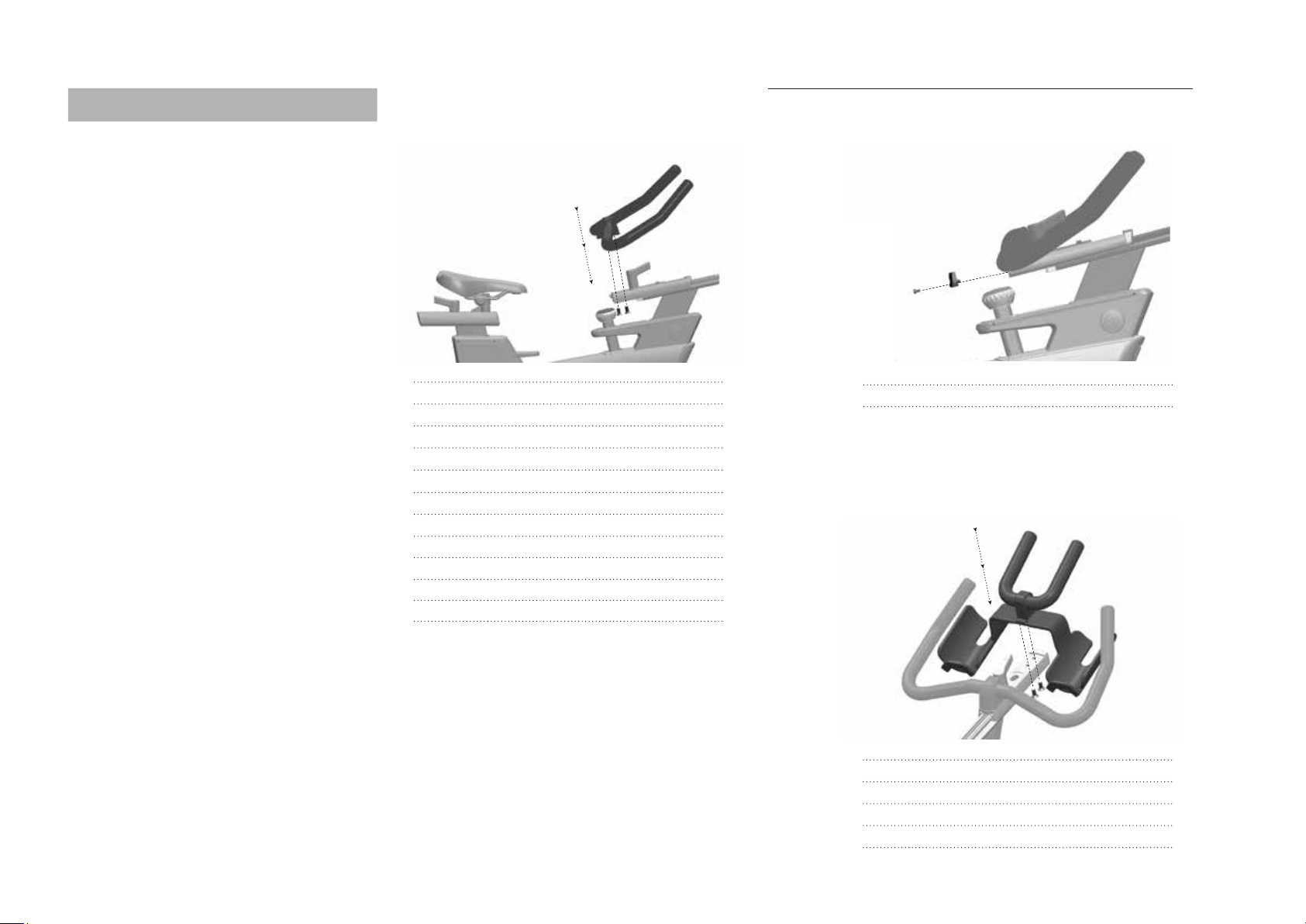
STEP 5 STEP 6
STEP 7
Assemble the handlebar
PLEASE NOTE
In order to avoid damaging the interior cabling, the
handlebars must not to be adjusted horizontally before this
step.
Ensure that bolts are tightened with sufficient force (30Nm)
when mounting the handlebars. The fastening counter sunk
bolts are coated with TufLok® at the factory to prevent
them from becoming loose during use. If bolts are loosened
after initial assembly, we recommend using medium—strength
LOCTITE®2701 when reassembling.
Assemble the handlebar
Set the vertical adjustment of the handlebar stem to the
highest position before beginning with assembly.
Screw, countersunk (16)
GC—Assemble the Cap, end, track, HB, rear
PLEASE NOTE
COMPONENTS ANDTOOLS
Tapping screw, M4 x 8L (15)
Screw, countersunk (16)
COMPONENTS ANDTOOLS
COMPONENTS ANDTOOLS
Intenza 550GC Series Cycle Handbook: 550GC Series Cycle Assembly Instructions
550GC Series Cycle Assembly Instructions
WARNING Do not remove warning tape from the sliders
prior to the handlebar being assembled.
After assembly, remove the warning tape. Do not move
horizontal slider backwards.

EN
9
PLEASE NOTE
GC3—Assemble the handlebar and cover
Socket screw (22)
COMPONENTS ANDTOOLS
Dome screw (13)
COMPONENTS ANDTOOLS
550GC Series Cycle Assembly Instructions
STEP 8—1
PLEASE NOTE
GC3—Assemble the console
Connect the cable first then assemble the console
Dome screw (13)
COMPONENTS ANDTOOLS
STEP 8—3
GC3—Assemble the brcket and cover
STEP 8—2
Set the vertical adjustment of the handlebar stem to the
highest position before beginning with assembly.
Intenza 550GC Series Cycle Handbook: 550GC Series Cycle Assembly Instructions
EN
10
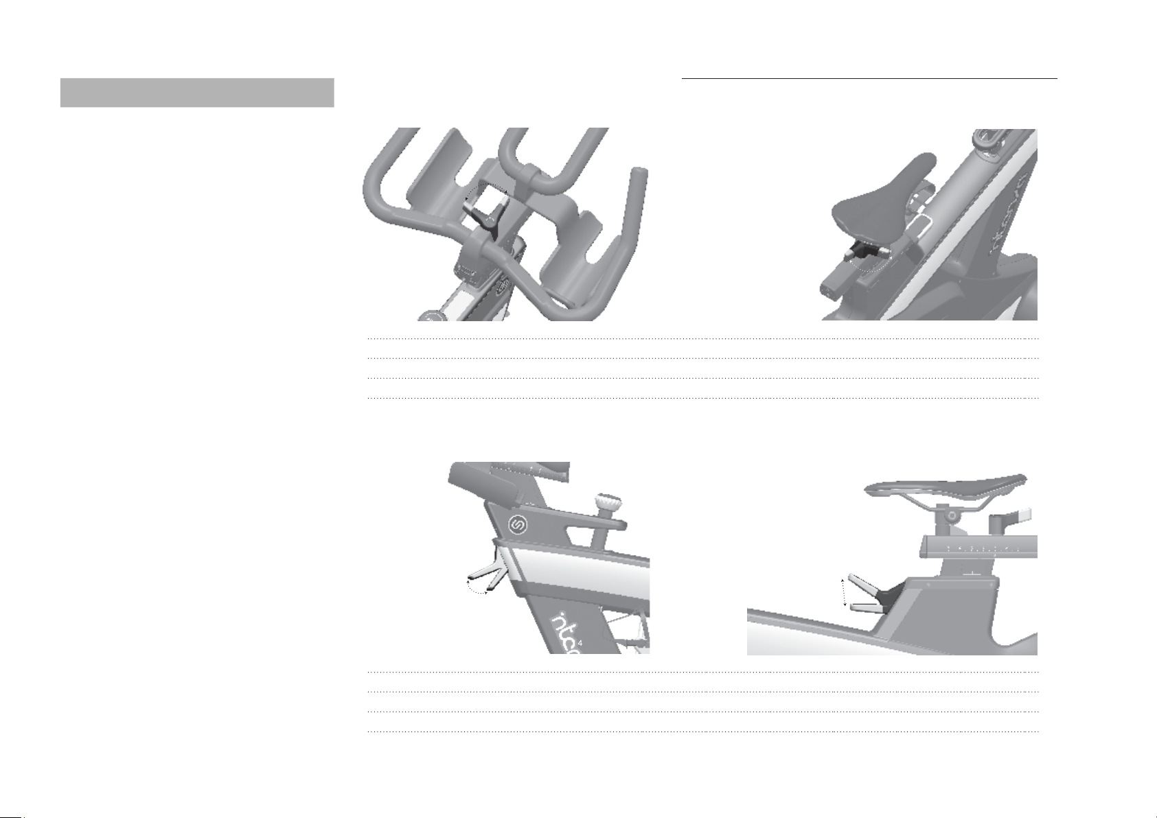
STEP 9
Check the horizontal adjustment of the handlebars
STEP 10
Check the clamping force of the horizontal adjustment
Check the horizontal adjustment of the handlebars, with the thumb lever opened, for ease of motion when adjusting.
Check the clamping force of the horizontal adjustment. Make sure the horizontal adjustment lever is fully tightened.
Adjust if required, referring to service guidelines available on manufacturer‘s service website or contact your local distributor.
Check the vertical adjustment, with the flip lever opened, for ease of motion when adjusting.
Check the clamping force of the vertical adjustment with the flip lever closed. Make sure the vertical adjustment lever is fully tightened.
Adjust if required, referring to service guidelines available on manufacturer‘s service website or contact your local distributor.
STEP 11
Check the vertical adjustment
STEP 12
Check the clamping force of the vertical adjustment
Intenza 550GC Series Cycle Handbook: 550GC Series Cycle Assembly Instructions
550GC Series Cycle Assembly Instructions

EN
11
STEP 13
Assemble the Pedal assy, L, standard
STEP 14
Assemble the Pedal assy, R, standard
Intenza 550GC Series Cycle Handbook: 550GC Series Cycle Assembly Instructions
550GC Series Cycle Assembly Instructions
WARNING! Attach the pedal marked Ron the right crank
and tighten by turning clockwise (standard right—hand
thread). Attach the pedal marked Lon the left crank and
tighten by turning counter—clockwise (left—hand thread).
Please make sure that both pedals are fastened with
sufficient force (55 NM), to ensure that the bolt does not
become loose during use.
The threads are provided with TufLok®at the factory
to prevent them from becoming loose during use. If bolts
are loosened after initial assembly, we recommend using
medium—strength LOCTITE® 243 when reassembling.

EN
12 Intenza 550GC Series Cycle Handbook: 550GC3 Console Overview
550GC3 Console Overview
550GC3 Console is powered by generator.
· Generator stores power in rechargeable batteries.
· Batteries power the console.
Turn on the console
Simply pedal or press any button on the console.
Turn off the concole
When the console is idle for more than 15sec., the screen will shut down;
Pedaling or pressing any button will turn on the screen again.
When the bike is idle for more than 2min., the console will go in Stand—by
mode and shows Turn—off. The animation will appear prior to shut down.
During Stand—by mode all data will be saved; Pedaling or pressing any
button will turn on the screen again.
When the bike remain in Stand—by mode for 8 minutes, all data will be deleted.
Pedaling or pressing any button will turn on the screen again.
Colour Indicator for Standard Mode
Color Indicator for HR Mode
*WARNING! Heart rate monitoring systems may be inaccurate. Over exercising may
result in serious injury or death. If you feel faint stop exercising immediately.
**For speed within 50—80 rpm, the accuracy range of power is 10%.
A
........................................................................................ .
B
........................................................................................ .
C
........................................................................................ .
A+C
........................................................................................ .
Press—Switch page
PAGE 1
PAGE 2
PAGE 3
Hold 3 sec.—Switch page automatically
Press—Pause
When button Bis pressed, no matter if the
user is pedaling or not, all data calculation
will be paused and the console will
consecutively present all 3 data pages.
When the console is paused, press the
Button Bagain and you will return to the
data calculation mode.
Hold 3 sec.—Date reset
Press—Select the MODE
Standard Mode
HR Mode
When in mode selection
Button A
Button B
Hold Button B for 3sec.
ButtonC
Change Metric/imperial system
Avg. Cadence
Avg. Power
Avg. Speed
Level
Elapse time
Max. Cadence
Max. Power
Max. Speed
Level
Elapse time
Calories
Distance
Heart Rate*
Level
Elapse time
Previous
Confirm
Exit
Next
A B C
ZONE 1
WHITE LIGHT
<140 Watt
ZONE 2
BLUE LIGHT
140—189 Watt
ZONE 3
GREEN LIGHT
190—226 Watt
ZONE 4
ORANGE LIGHT
227—264 Watt
ZONE 5
RED LIGHT
>265 Watt
ZONE 1
WHITE LIGHT
<60% MHR
ZONE 2
BLUE LIGHT
60—70% MHR
ZONE 3
GREEN LIGHT
70—80% MHR
ZONE 4
ORANGE LIGHT
80—90% MHR
ZONE 5
RED LIGHT
90—100% MHR

EN
13
Make sure that you maintain the proper safety space as shown below around the equipment.
Safety Space and Insrallation
80cm/31inches
80cm/31inches
80cm/31inches
80cm/31inches
80cm/31inches
Installation
· Instructions stated in this manual must be performed during initial installation of the Intenza 550GC in order to ensure optimal
performance and a long lifespan. Please read and adhere to the following instructions carefully. If 550GC is not installed and
configured as described, the components may be subjected to excessive wear and tear and the bike may become damaged.
If you have any questions regarding installation, please contact us.
· Make sure the bike is level. If bike rocks on the floor, turn the levelling feet underneath the front and/or rear stabiliser until the
rocking motion is eliminated. Make sure that the levelling feet are not extended further than 10 mm.
· Verify emergency brake function to make sure that it is working properly.
· Check that both crank arm Allen bolts, with which the cranks (on the right and left side of the bottom bracket) are fastened, are
secure (tightening torque 60 NM). These bolts are provided with TufLok®at the factory to prevent them from becoming loose
during use. If the bolts become loose, we recommend applying medium—strength LOCTITE® 243 and then re—attaching the
crank fixing bolts with a tightening torque of 60 NM.
· Wipe down bike frame with a rag moistened with solvent—free spray lubricant.
· Some parts of the bike may become loose during shipment. Check crank arms and all exposed screws, bolts and nuts, and make
sure that they are all secure and properly tightened.
Intenza 550GC Series Cycle Handbook: Installation
EN
14
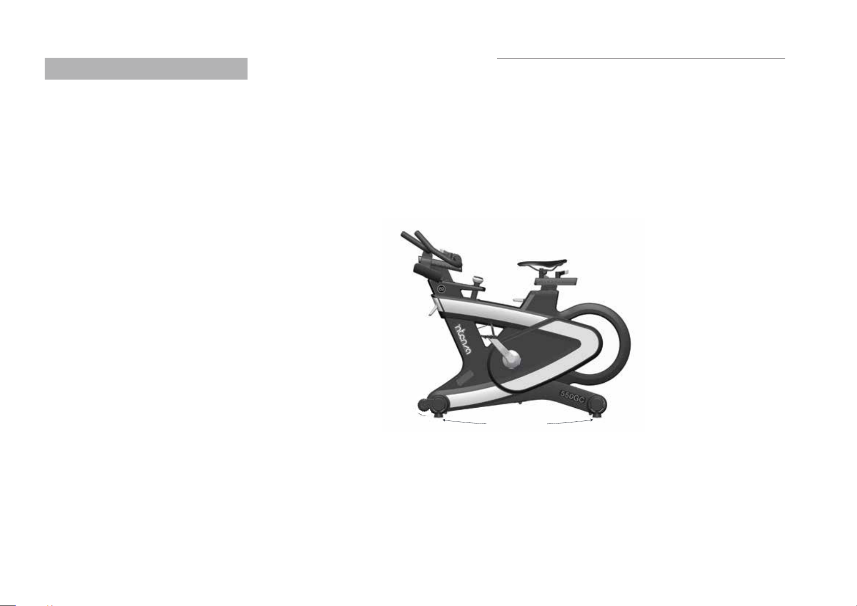
Leveling 550GC Series Cycle
Check the stability of where 550GC Series Cycle is to be operated and if necessary adjust the levelling feet underneath the front, or rear,
stabilisers to ensure the desired stability. It is important that all four of the leveling feet touch the ground in order to keep the bike
stable at all times. To adjust, turn the leveling feet counterclockwise to decrease the height or clockwise to increase the height until
the bike is stable.
It is recommended that two people move 550GC Series Cycle.
In order to prevent accidents and damage to the handlebar plug—in sockets, it is necessary to firmly fix vertical handlebar adjustment
before the wheel is tilted. Please be extra cautious when moving 550GC Series Cycle over uneven surfaces: it is advised
that a second person assist in order to prevent the cycle from tilting to one side.
Allow a minimum safety distance away from the nearest equipment, objects or walls as illustrated below.
Stand in front of the bike, grasp the handlebars and tilt the bike towards you until the transportation wheels are touching the floor.
Roll the bike to the desired location, then gently lower the rear of the bike back to the floor.
Moving and Leveling 550GC Series Cycle
IMPORTANT A complete visual inspection, and test of the
features and functions of the assembled exercise bicycle
should be made prior to use.
Please do not unscrew the levelling feet more
than 1 cm. The free standing 550GC Series can only be
installed and operated on a stable and leveled floor.
Intenza 550GC Series Cycle Handbook: Moving and Leveling The 550GC Series Cycle
LEVELLING FEET
EN Foot Position
Place the balls of your feet securely in the toe straps so that they are centred on the pedals.
Foot Strap
Adjust the toe straps to hold your foot firmly on the pedal, allowing you to apply force throughout every part of the pedal stroke.
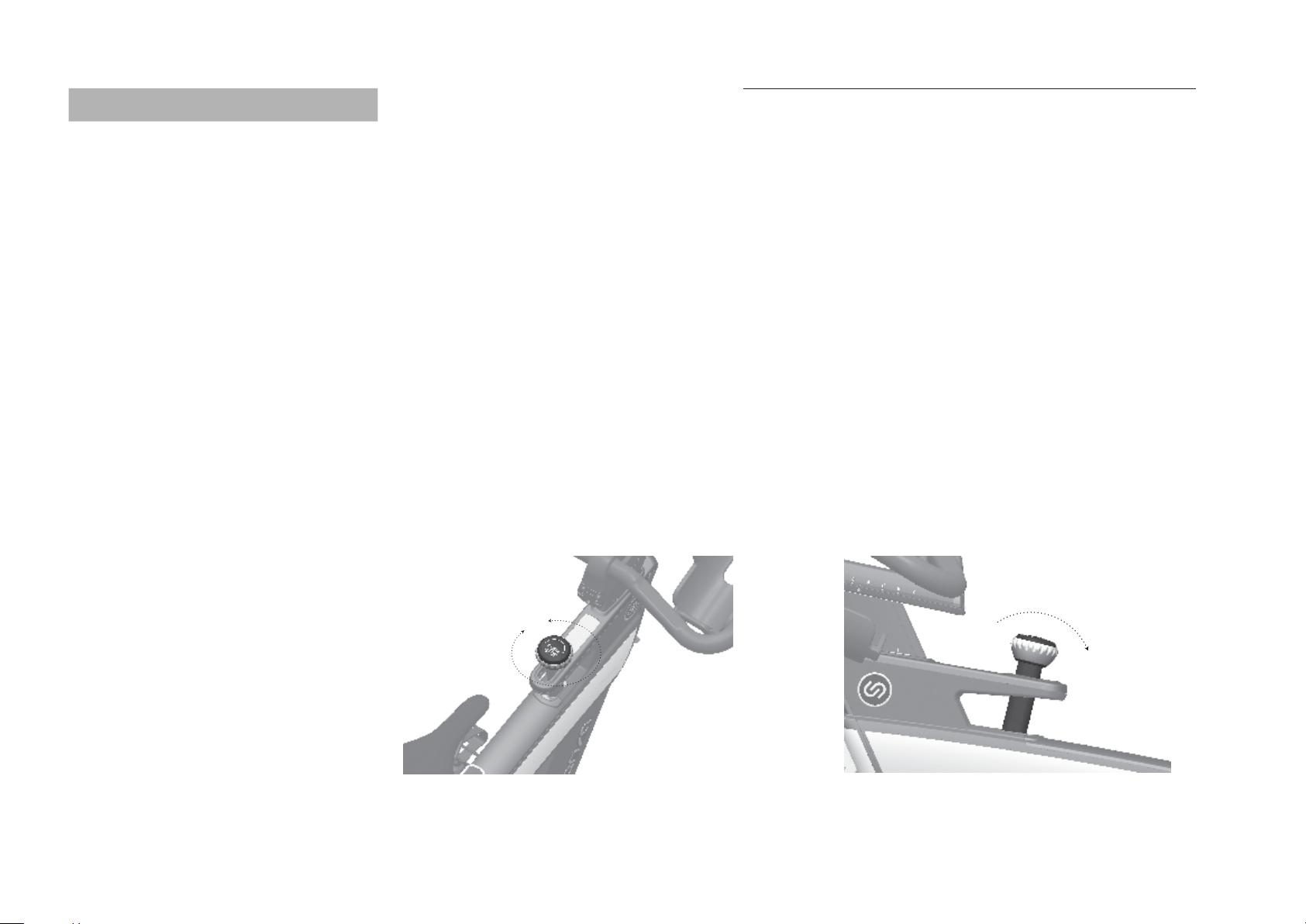
· The resistance adjustment can be set precisely and regulated in micro increments according to the requirements of the cyclist using
the resistance adjustment knob with a range of motion of 240°.
· To increase the resistance, turn the resistance adjustment knob clockwise. To decrease the resistance, turn it counterclockwise.
For a magnetic brake system, like the one fitted to this 550GC, the magnetic resistive effect also increases with pedalling
frequency.
· Never pedal backwards under resistance, as this can loosen the screws between the pedals and the crank arm and the two may even
become detached. To stop the flywheel during use, the resistance knob/emergency brake knob must be pressed down. During
training, please make sure your shoes are placed in the toe clips (cages) provided or if you are using cycling shoes, that they are
connected with the SPD cleats
· 550GC does not have a free—moving flywheel. The flywheel is firmly connected to the pedals and does not stop independently if
the user stops pedalling. Please always check your movements and reduce speed in a controlled manner to stop or simply press the
red resistance/emergency brake knob down to quickly slow down the movement and in so doing bring the flywheel to a stop and
suspend the training session.
· Emergency brake = press down red resistance/emergency knob.
· If the emergency brake has been activated, it may only be disengaged again once the flywheel has come to a complete standstill and
the pressure has been removed from the pedals.
PRESS
240
15
How To Operate Intenza 550GC Series
Intenza 550GC Series Cycle Handbook: How To Operate Intenza 550GC Series
Resistance Knob (Turn Resistance Adjustment Knob) Emergency Brake (Press Resistance Adjustment Knob)
WARNING 550GC should only be operated in a forward
pedaling motion.
The emergency brake functionality is limited when
pedaling backwards. Do not attempt to adjust seat and
handlebar in vertical or horizontal position while riding or
seated.
EN
WARNING Ensure that all levers (vertical and horizontal)
are closed, before sitting on the bike and always step off
the bike when making adjustments to the handlebars
and/or saddle.
OPEN
VERTICAL HANDLEBAR
ADJUSTMENT
MAXIMUM HANDLEBAR
HEIGHT INDICATOR
MAXIMUM SEAT
HEIGHT INDICATOR
VERTICAL SADDLE
ADJUSTMENT
CLOSED
OPEN
CLOSED
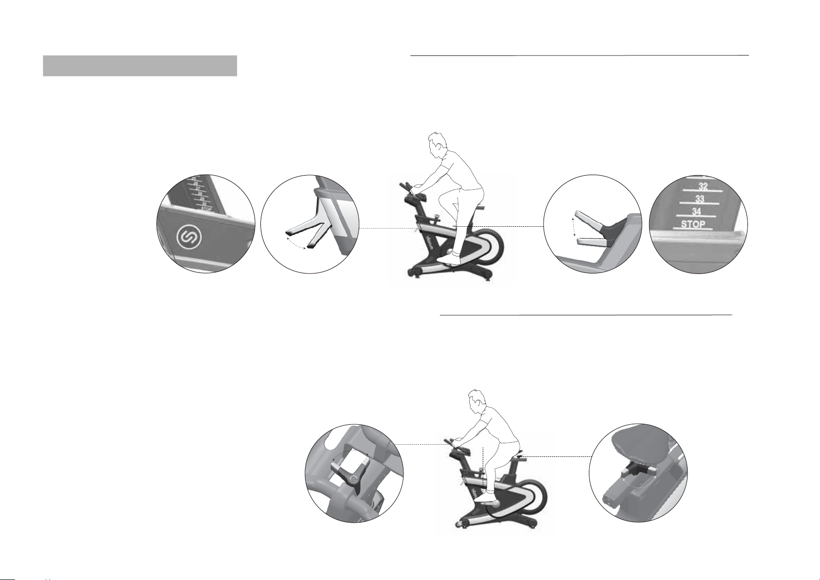
Adjusting The Saddle Height
Sit on the saddle and ensure that your hip is not tilted to one side when the pedal has assumed the position as shown in the picture.
Place your shoes in the toe clips (cages) on the pedals, or in the SPD cleats if you are using cycling shoes, if your Group Cycle is not
fitted with a combi pedal system. Reduce your risk of injury and enjoy a more comfortable ride by adjusting the seat height so that
there is a slight bend (25—35 degrees) in your knee at the bottom of a pedal stroke.
Adjusting The Saddle Horizontally
Properly positioning the saddle horizontally is very important in order to avoid injury to the knees. Sit on the saddle and move the
pedals until the crank arms are in a horizontal position. The knee of your forward—facing leg should be positioned directly above the
centre of the pedal. If this does not correspond to your bike’s setting, please align the horizontal saddle adjustment to the front or
rear in order to attain this seat position.
OPEN CLOSED
OPEN
CLOSED
HORIZONTAL
HANDLEBAR ADJUSTMENT
HORIZONTAL
SADDLE ADJUSTMENT
16 Intenza 550GC Series Cycle Handbook: How To Adjusting Intenza 550GC Series
EN
WARNING Ensure that all levers (vertical and horizontal)
are closed, before sitting on the bike and always step off
the bike when making adjustments to the handlebars
and/or saddle.
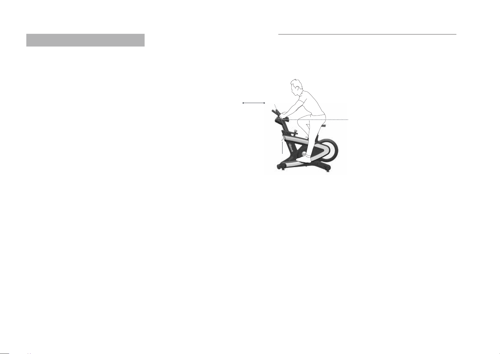
Adjusting The Handlebar Positioning
Begin with the top of the handlebars at approximately the same height as the saddle (dotted horizontal line A as in the drawing below)
for inexperienced users set to the “0” marking (see dotted vertical line B as in the drawing below). If your knees touch the handlebars
or if you experience back discomfort when pedalling in the standing riding position for extended periods, the handlebars should first
be adjusted slightly higher.
The next step is to adjust the horizontal position of the handlebars as precisely as possible in relation to your height. An ideal and
protective seating position for inexperienced riders is achieved if your back assumes an inclination of an angle of 45°. The handlebars
offer a wide variety of hand positions and adjustment possibilities, which provide the experienced rider with every possibility to find
his/her ideal seating and hand positioning. It is recommended to change hand positions frequently during extended workouts in order
to minimise one—sided and monotonous exertions on your muscles, ligaments and joints.
A
VERTICALLY
ADJUSTING THE HANDLEBARS
USING THE LEVER
HORIZONTALLY
ADJUSTING THE HANDLEBARS
USING THE LEVER
B
17
Intenza 550GC Series Cycle Handbook: How To Adjusting Intenza 550GC Series

EN
18
Preventive Maintenance
Troubleshooting
CHECKLIST
· Verify the symptom/s and review the operating instructions.
· The problem may be unfamiliarity with the product, its features or the workout programs.
· Check the error message, then follow the instructions in the service manual.
· If the problem you encounter has not been solved by the above steps, and the Intenza 550GC Series Cycle is still not operational,
locate and document the serial number of the unit, and contact your local dealer.
The serial number contains six digits, and there is one location you can find Intenza 550GC Series serial number—
· Located on the bottom that near main body.
WHERE IS THE SERIAL NUMBER OF THE PRODUCT
Intenza 550GC Series Cycle Handbook: Preventive Maintenance
PLEASE NOTE Replace defective components immediately
or keep the equipment out of use until the equipment
undergoes repair.
WARNING
· Please carefully observe the following instructions. The maintenance and care procedures set out must be performed regularly to
ensure maximum operating safety and lifespan. Irregularly observed maintenance and care procedures will lead to increased wear to
the product and will void the warranty. If you have any further questions on this topic, please contact our technical support.
· Please use only acid and solvent—free maintenance and care agents (e.g. Brunox) as recommended by us, to prevent damage to
550GC Series components.
· Depending on the use and maintenance of the product, certain items can be replaced on a scheduled basis. We recommend that you
replace the belt and pedals every two years in order to keep the bike in top working order.
· Any other servicing should be performed by an authorized service representative.
DAILY MAINTENANCE
· Make sure that 550GC Series is leveled and does not rock
· Cleaning: 550GC Series Cycle must be regularly cleaned after each use for reasons of hygiene. Ensure that there are sufficient soft
cloths or paper towels, maintenance and disinfection agent available. First disinfect the saddle and handlebars with a suitable
agent and then wipe all bodily residues off the entire 550GC Series Cycle.
WEEKLY MAINTENANCE
· Cleaning: Depending on how often 550GC Series Cycle is used, it must be extensively cleaned once a week. To do this, spray a
maintenance agent onto a soft cloth and clean all plastic parts, the entire flywheel, exposed framework parts including stabilisers
and the plastic casing.
· Never spray the maintenance agent directly onto the flywheel, as this could cause the drive belt to slip through (belt slip) and may
have a negative impact on E—brake functionality.

EN
19
©2020 HealthStream Taiwan Inc.
No.28, Jiaotuizai Boulevard, Liuying District, Tainan City 736, Taiwan
intenzafitness.com
Printed in Taiwan
Version—2.0
Intenza 550GC Series Cycle Handbook: Specifications: Intenza 550GC Series Cycle
Intenza 550GC Series Cycle Specifications
Type
Design Use
Weight of GC
Maximum User Weight
User Height
Required Foot Print
Console
Battery
550GC3
Commercial
62.5kgs
159kgs/350 lbs
Suitable For Users Between
Approximately 149.5—205cm
Approximately 130 x 58cm
5”/DFSTN, view area—101.4 x 67.5mm,
LED backlight
Lithium mod. 18650, rechargeable 100,000 times
550GC
Commercial
60.5kgs
159kgs/350 lbs
Suitable For Users Between
Approximately 149.5—205cm
Approximately 130 x 58cm
550GC
1,300 mm 51.18 inches
580 mm 22.83 inches
55 kgs 121 lbs
550GC3
1,300 mm 51.18 inches
580 mm 22.83 inches
58 kgs 130lbs
ASSEMBLY DIMENSIONS
MODEL
LENGTH
WIDTH
WEIGHT
550GC
1280 mm 50.4 inches
230 mm 9 inches
1060 mm 41.7 inches
71.5 kgs 158 lbs
550GC3
1280 mm 50.4 inches
230 mm 9 inches
1060 mm 41.7 inches
73.5kgs 162 lbs
SHIPPING DIMENSIONS
MODEL
LENGTH
WIDTH
HEIGHT
WEIGHT
This manual suits for next models
3
Table of contents
Languages:
Other Intenza Exercise Bike manuals


Popular Exercise Bike manuals by other brands


Wonder Core
Wonder Core Cycle WCC-53 user guide
ICON Health & Fitness
ICON Health & Fitness PRO-FORM Le Tour de France CBC user manual

Body Solid
Body Solid Endurance B5R user manual

SOLE
SOLE SB700 owner's manual

Precor
Precor Bicycle-mounted Child Seat C842 Service manual

Schwinn
Schwinn Airdyne owner's manual