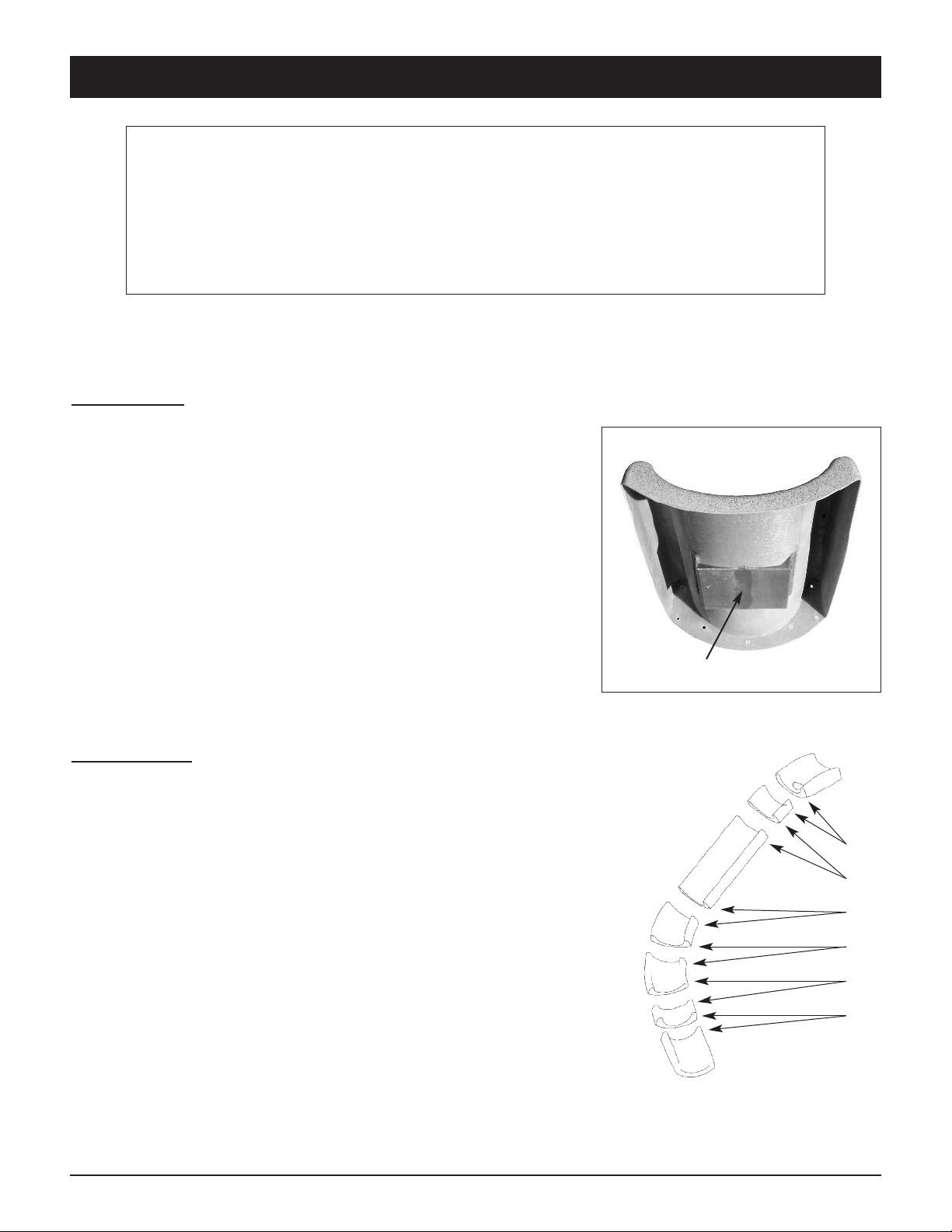
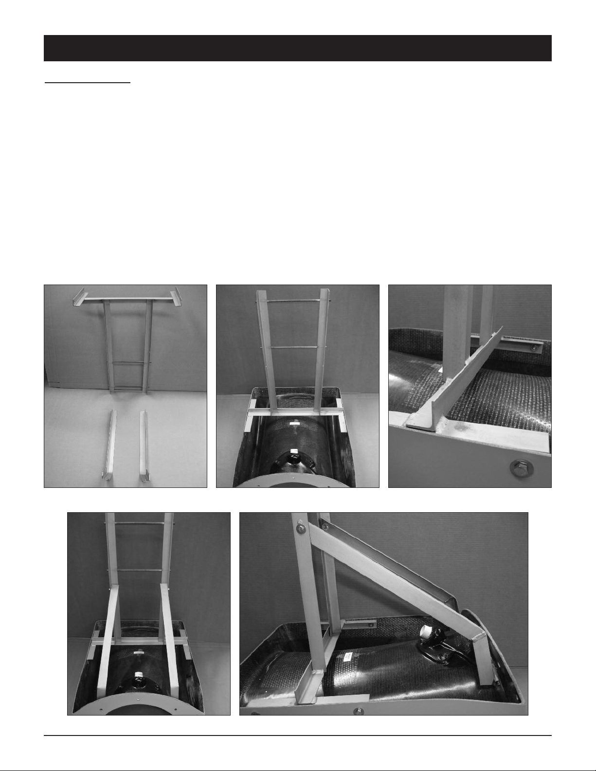
INSTALLATION INSTRUCTIONS BYOS 1 SLIDE
2
BYOS-IM Rev. 08/15 (SBK-BYOS INSTAL)
1. Everyone who uses this sli e must know, un erstan an follow these instructions
2. The ANSI/APSP/ICC-5 2011 stan ar for above groun pools prohibits the use of sli es or iving boar s
on above groun pools.
3. This sli e is esigne for resi ential ingroun pool use ONLY. This sli e may not be use on any above
groun pool. Such use of this sli e may result in serious injury or eath.
4. This sli e shoul never be installe on above groun pools, pon s, floating ocks or platforms, boat ocks
or houseboats or any natural bo y of water.
5. This sli e shoul never be installe on any commercial, public or semi-public pool.
6. Be familiar with the shape an epth of the pool before you sli e. This sli e shoul only be use with the
proper water safety envelope, as escribe in Diagrams A, B & C on page 3 an in accor ance with the
sli e positioning iagrams on page 4.
7. Because the sli e may only be use in water 4.5’ eep or greater, all sli e users must be able to swim
in eep water.
8. Weight limit for this sli e is 250 poun s, no sli er weighing more than 250 poun s may use this sli e.
9. The surface of the sli e is very slippery when wet; USE CAUTION when entering the sli e an when
transitioning from stan ing to sitting.
10. Sli e in a feet first sitting position ONLY.
11. IMPORTANT: sli ing hea first is prohibite : serious spinal injury resulting in paralysis or eath can result.
12. Maintain a ult supervision at all times.
13. Only one person at a time is allowe on the sli e.
14. Be sure the water elivery system is on an lubricating the sli e prior to use.
15. Collision with another swimmer or a iver can result in serious injury or eath for one or both persons:
Before sli ing, always make sure that the path in front of the sli e is free from any (inclu ing submerge )
obstructions inclu ing other people or objects in the pool such as rafts, inner tubes etc. When a iving
boar is also present, make sure you o not use the sli e while someone is on or using a iving boar .
Take turns.
16. No roughhousing or horseplay shoul be allowe on the sli e at any time.
17. Do not stan , jump or ive from any part of the sli e.
18. Do not sli e on objects such as rafts or inner tubes. oing so greatly increases your risk of injury.
19. Do not sli e through or at objects such as rafts or inner tubes, oing so greatly increases your risk of
injury.
20. Do not use this sli e if physically impaire or han icappe without your octor’s permission.
21. Do not use this sli e with a history of heart con itions, seizures, back problems, fainting or fear of
heights.
22. Do NOT use this sli e if you are pregnant.
23. Do not rink alcohol an use this sli e.
24. Don’t take chances, inspect the sli e at least once a year (see the sli e inspection list on page 16, o
not use the sli e if any part becomes loose, amage , weakene or broken. If necessary, before using
the sli e again, have it inspecte an repaire by a competent professional familiar with pool sli es.
SLIDE IN A SITTING
POSITION ONLY
Face forwar on the sli e, hol ing the legs an arms
with the palms of your han s forwar an tilte up.
WARNING SERIOUS INJURY OR DEATH CAN RESULT FROM THE
IMPROPER INSTALLATION OR USE OF THIS SLIDE.
DO NOT SLIDE HEAD FIRST SERIOUS INJURY
CAN RESULT DEEP WATER
SWIMMERS
ONLY
INTENDED USE
INSTRUCTIONS
WARNING