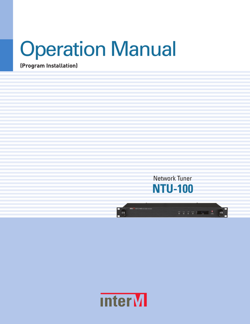
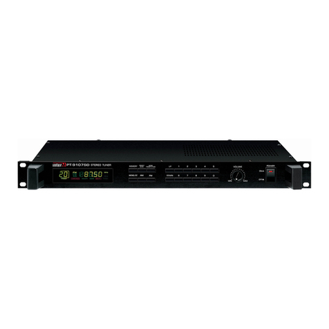
Inter-m PT-9107S User manual

PT-9107S Stereo Tuner
PT
9107S
STEREO TUNER
MONO
MHz
KHz
OC03
OC03
OC03

Contents
Contents
1. Unpacking and Installation.....................................................................................................1
2. Features ................................................................................................................................2
3. Front Panel Controls...............................................................................................................3
4. Rear Panel Controls ...............................................................................................................5
5. Installation of the Speaker......................................................................................................5
6. Applications of the Antenna ...................................................................................................6
7. Warning................................................................................................................................7
8. Applications ..........................................................................................................................8
9. Block Diagram.......................................................................................................................9
10. Specifications.....................................................................................................................10
OFFICE :
653-5 BANGHAK-DONG, DOBONG-KU, SEOUL, KOREA
TEL : 82-2-2289-8140~8, FAX : 82-2-2289-8149
Home Page : http://www.inter-m.com
E-mail : [email protected]

1
PT-9107S
STEREO TUNER
Unpacking and Installation
Athough it is neither complicated to install nor difficult to operate your set, a few minutes of your time is
required to read this manual for a properly wired installation and becoming familiar with its many features
and how to use them. Please take a great care in unpacking your set and do not discard the carton and
other packing materials. They may be needed when moving your set and are required if it ever becomes
necessary to return your set for service. Never place the unit near radiators, in front of heating vents, in
excessively humid or dusty location to avoid early damage and for your years of quality use. Connect your
complementary components as illustrated in the following page.
RISK OF ELECTRIC SHOCK
DO NOT OPEN
CAUTION
CAUTION: TO REDUCE THE RISK OF ELECTRIC SHOCK.
DO NOT REMOVE COVER (OR BACK).
NO USER-SERVICEABLE PARTS INSIDE.
REFER SERVICING TO QUALIFIED SERVICE PERSONNEL.
WARNING
To prevent fire or shock hazard, do not
expose the unit to rain or moisture.
This symbol is intended to alert the user to the
presence of uninsulated “dangerous voltage”
within the product’s enclosure that may be of suf-
ficient magnitude to constitute a risk of electric
shock to persons.
This symbol is intended to alert the user to the
presence of important operation and mainte-
nance (servicing) instructions in the literature
accompanying the appliance.
Caution: To prevent electric shock do not use this (polarized) plug
with an extension cord, receptacle or other outlet unless
the blades can be fully inserted to prevent blade expo-
sure.
Attentions: Pour prévenir les chocs électriques ne pas utiliser cette
fiche polarisée avec un prolongateur, une prise de
courant on une autre sortie de courant, sauf si les
lames peuvent étre insérées à fond sans en laisser
aucune partie à découvert.
* Do not install this apparatus in a confined space such as a book case or similar unit.
* The apparatus shall not be exposed to dripping or splashing and no objects filled with liquids, such as vases,
shall be place on the apparatus.
2PT-9107S
STEREO TUNER
Features
Features
- HIGH PERFORMANCE FM/AM TUNER
This tuner incorporated FRONT END whit FET, high sensitivity circuitry.
- FIXED AND VARIABLE OUTPUT
This unit is provided 1 fixed output and 2 variable output. Variable output is controlled with volume on the
front panel.
- AUTO SCAN, AUTO SCAN MEMORY
The frequency is increase and decrease by 1 step when you press the UP/DOWN switch, more than 2 sec
then the function is charge to auto SCAN mode automatically.
If MEMORY KEY is that press more than 2 seconds, AUTO SCAN MEMORY function achieve.
- MONO/STEREO FUNCTION
- 20 FREQUENCY MEMORIES
This tuner is able to memory 20 frequencies each AM/FM, and each memorized frequency is accessible
during 5 sec by using PRESET SCAN switch.
- FM STEREO MUTE CIRCUIT
This unit employed muting circuitry and eliminates noise when tuner is not tuned frequency in stereo state.
- USE OF EMERGENCY BATTERY
You can operate this by use of emergency battery for unexpected AC power failure.

3
PT-9107S
STEREO TUNER
Front Panel Controls
1. POWER SWITCH
Pressing this switch to ON will make the power indicating LED light and supply the power to this unit.
2. VOLUME
This control is used for adjusting the variable output (4, 6 of rear panel).
3. UP/DOWN SWITCH
When the switch is pressed one time, AM/FM frequency is up and down by one step. And in case of
pressing continually, the frequency is up and down fastly. Also when the frequency is matched, it
automatically stops.
4. FM/AM BAND SELECTOR
This switch is used to select AM or FM.
5. MONO/ST
This switch is used to select MONO/STEREO FUNCTION in FM.
6. TUNED
This TUNED indicates tuning for absolute of AM and FM signals ensuring minimum distortion and
maximum output.
7. MEMORY INDICATE (Number 10 Switch)
This indicator is for memorizing the broadcasting frequency.
8. FM/AM BAND INDICATE (Number 4 Switch)
This indicator is used for selecting AM or FM.
9. PRESET
This indicator is display of the memory state.
PT
9107S
STEREO TUNER
MONO
MHz
KHz
1213121110
987 6 5 4 3

4PT-9107S
STEREO TUNER
10. MEMORY SWITCH
This switch is for memorizing the broadcasting frequency.
- Method 1
A. Select the frequency that you want to memorize by the UP/DOWN switch and press 4(memory
switch).
B. Press 4(memory switch) then select the desirable address when 13(address selector switch).
C. Present status of tuner will be memorized in selected address.
- Method 2
A. Select the frequency that you want to memorize by the UP/DOWN switch and press 4(memory
switch).
B. Press 4(memory switch)
C. Present status of tuner will be memorized in 1 address.
D. If A and B action repeat, present status of tuner will be memorized in next address.
11. PRESET/SCAN
When the switch is pressed one time, memorized broadcasting can be listening sequentially during five
seconds. (The status display at the Number 9 of LCD.)
12. MODE PRESET/TUNE
When you press the UP/DOWN switch,
MODE PRESET is increase and decrease by 1 channel.
MODE TUNE is increase and decrease by 1 step.
13. ADDRESS SELECTOR SWITCH
20 kinds address are prepared and each address is accessible by this switches.

5
PT-9107S
STEREO TUNER
Rear Panel Controls
Rear Panel Controls
1. AC INLET
This terminal is connected AC input cord.
2. DC INPUT TERMINALS
This terminal is for connecting DC power supply or battery. Connect red colored terminal to positive lead
of battery and black colored one negative lead of battery.
3. FIXED MONO OUTPUT JACK
This jack is for connecting to the input jack of preamplifier or mixer. The level of this output is not adjust-
ed by volume (2 of front panel) control on the front panel.
4. VARIABLE MONO OUTPUT JACK
This jack is for connecting to the input jack of preamplifier or mixer. The level of this output is adjusted
by volume (2 of front panel) control on the front panel.
5. RESET
When the power switch ON, this unit might error. When this unit error, at first press power switch to
OFF, and press this switch for 2~3 second.
6. VARIABLE STEREO OUTPUT
This jack is for connecting to the input jack of preamplifier or mixer. The level of this output is adjusted
by volume (2 of front panel) control on the front panel.
7. ANTENNA TERMINAL
- FM TERMINAL: You can connect 75 ohms cable.
- AM TERMINAL: Connect the AM loop antenna.
8. FUSE COVER
This fuse holder contain AC fuse, replace only with same type fuse when it is blown out. If it continuously
low, stop replacing fuse and refer servicing to qualified personnel.
9
!"#!"#
$
SNwww.inter-m.com
% %
& !
' %
CAUTION;
AVIS;
&
( ! (
CAUTION;
& )
'
!! (
! !
21347
58 6

6PT-9107S
STEREO TUNER
Application of The Antenna
- FM RECEIVING ANTENNA
First of all, you have to connect FM antenna in the box. But, The electric wave of FM broadcasting is able to
weaken in the case of hills and valleys, around buildings and in iron-reinforced buildings.
- INSTALLATION OF ANTENNA EXCLUSIVELY FOR FM
Listening to the broadcasting, fix the antenna after deciding the location and the direction so that the recep-
tion may be optimized.
- INSTALLATION OF ANTENNA USING THE COAXIAL CABLE
Noisy reception may occur in built-up areas and factory sites as well as around power cables. This may be
the case even when an antenna is used exclusively for FM. In these regions, install the antenna using 75Ω
coaxial cable.
- INDOOR ANTENNA
In the regions where FM broadcasting is heard comparatively well due to the near distance to the station or
wooden structure, you can receive broadcasting of good quality by using T-type antenna.(using matching
trans: 300Ω/75Ω)
- AM LOOP ANTENNA
Tuning the electric wave of AM broadcasting, you have to connect AM loop antenna in the box.
Fix one end of AM loop antenna single cable to the AM terminal and the other end to GND.
- AM OUTDOOR ANTENNA
Install the vinyl-coated cable to an outdoor place if the AM reception is not good enough.
/70
T-type ANTENNA

7
PT-9107S
STEREO TUNER
Warning: Do not Install Antennas Near
Power Lines or Service Entrances
Warning: Do not Install Antennas Near
Power Lines or Service Entrances
- THE FOLLOWING INSTRUCTIONS ARE FOR EXTERNAL ANTENNA INSTALLATION:
“Antenna System–This receiver, tuner or tuner-amplifier is intended for connection to an antenna system,
including outdoor antennas or community antenna television (CATV) systems, installed to provide some pro-
tection against voltage surges and built up static charges. Articles 810 and 820 of the National Electrical
Code, ANSI/NFPA 70–1984, provide information with respect to grounding of the mast and supporting
structure, the lead-in wire to an antenna discharge unit, and the coaxial cable system; and with respect to
the size of grounding conductors, location of antenna-discharge units, connection to grounding electrodes,
and the requirements for the grounding electrode. If an outside antenna is connected to the antenna termi-
nal of the tuner, be sure the antenna system is grounded in a manner similar to the accompanying Figure.”
(See Figure 67.1).
aUse No. 10 AWG (5.3 mm2) copper, No. 8 AWG (8.4 mm2) aluminum, No. 17 AWG (1.0 mm2)
copper-clad steel or bronze wire, or larger, as a ground wire.
bSecure antenna lead-in and ground wires to house with stand-off insulators spaced from 4–6 feet
(1.22–1.83m) apart.
cMount antenna discharge unit as close as possible to where lead-in enters house.
dUse jumper wire not smaller than No. 6 AWG (13.3 mm2) copper, or the equivalent, when a separate
antenna-grounding electrode is used. See NEC Section 810-21(f).
S2898
BONDING JUMPERd
POWER SERVICE GROUNDING
ELECTRODE SYSTEM
(e.g.interior metal water pipe)
SERVICE
ENTRANCE
EQUIPMENT
GROUND WIRE
a,b
GROUND CLAMPS
SERVICE ENTRANCE
CONDUCTORS
POWER LINES
GROUND CLAMP
STANDOFF
INSULATORSb
MAST
ANTENNA
LEAD-IN WIRE
ANTENNA
DISCHARGE
UNITc
TO EXTERNAL ANTENNA
TERMINALS OF PRODUCT
GROUND WIREa,b
GROUND CLAMPS
OPTIONAL ANTENNA GROUNDING ELECTRODE
DRIVEN 8 FEET (2.44m) INTOTHE EARTH
IF REQUIRED BY LOCAL CODES.SEE NEC
SECTION 810–21(f).
FIGURE
EXAMPLE OF ANTENNA GROUNDING CORRELATING WITH
NATIONAL ELECTRICAL CODE INSTRUCTIONS
CONTAINED IN ARTICLE 810–"RADIO AND
TELEVISION EQUIPMENT"

8PT-9107S
STEREO TUNER
Applications
Applications
!"
#
$
%
%
& ' % '
9
()()
%#
SNwww.inter-m.com
*
% +, %
- -
, % %
% - %
CAUTION;
AVIS;
CAUTION;
%

9
PT-9107S
STEREO TUNER
Block Diagram
Block Diagram

10 PT-9107S
STEREO TUNER
Specifications
Specifications ..........................................................0dB=0.775Vrms
- ELECTRICAL
Tuning Range ....................................................................................................FM: 87.5MHz~108MHz
.........................................................................................................................AM: 522kHz~1611kHz
...................................................................................................AM: 530kHz~1720kHz (UL/CSA only)
Sensitivity ...................................................................................................................FM: Less than 3uV
.............................................................................................................................AM: Less than 100uV
S/N.......................................................................................................................FM: Better than 65dB
............................................................................................................................AM: Better than 40dB
T.H.D......................................................................................................................................FM: 0.3%
................................................................................................................................................AM: 1%
Output Level
FM .................................................................................................Mono Balance: 1V (modul. 75kHz)
.........................................................................................................Stereo: 500mV (modul. 75kHz)
AM .............................................................................................Mono Balance: 240mV (modul. 30%)
Antenna Input ..........................................................................................................................FM: 75Ω
.......................................................................................................................................AM: Loop Ant.
- GENERAL
Power Source ...................................................................................AC 100V–240V, DC 24V 50/60Hz
Power Consumption .......................................................................................................................11W
Weight.........................................................................................................................................3.5kg
Dimensions.................................................................................................482(W) 44(H) 280(D)mm
* Specifications and design subject to change without notice for improvements.

NOTE

NOTE

MADE IN KOREA
9007983710
Other manuals for PT-9107S
2
Table of contents
Other Inter-m Tuner manuals

Inter-m
Inter-m PAM-MPM4 User manual

Inter-m
Inter-m TU-6200 User manual

Inter-m
Inter-m PAM-MPM4A User manual

Inter-m
Inter-m PT-9107SD User manual

Inter-m
Inter-m NTU-100 User manual

Inter-m
Inter-m PT-9107S User manual

Inter-m
Inter-m PAM-T User manual

Inter-m
Inter-m PT-9107S User manual

Inter-m
Inter-m TU-610 User manual

Inter-m
Inter-m NTU-100 User manual