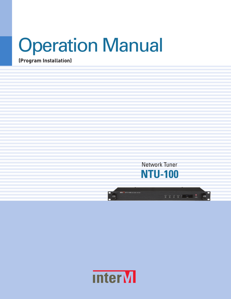
Inter-m NTU-100 User manual

Operation Manual
Network Tuner
NTU-100

NETWORK TUNER
Welcome
Welcome
A personal welcome to you from t e management and employees of Inter-M
All of the co-workers here at Inter-M are e icate to provi ing excellent pro ucts with inherently goo value,
an we are elighte you have purchase one of our pro ucts.
We sincerely trust this pro uct will provi e years of satisfactory service, but if anything is not to your complete
satisfaction, we will en eavor to make things right.
Welcome to Inter-M, an thank you for becoming part of our worl wi e exten e family!
RI K OF ELECTRIC HOCK
DO NOT OPEN
CAutION
CAUTION: TO REDUCE THE RI K OF ELECTRIC HOCK.
DO NOT REMOVE COVER (OR BACK).
NO U ER- ERVICEABLE PART IN IDE.
REFER ERVICING TO QUALIFIED ERVICE PER ONNEL.
WARNING
To prevent fire or shock hazard, do not
expose the unit to rain or moisture.
*WARNING FOR YOUR PROTECTION PLEA E READ THE FOLLOWING-WATER AND MOI TURE: Unit should not be used near water(e.g.
near a bathtub, washbowl, kitchen sink, laundry tub, in a wet basement, or near a swimming pool, etc). Care should be taken so than objects do
not fall and liquids are not spilled into the enclosure through openings.
*CLA 2 WIRING (Adjacent to speaker terminal): The speaker output of this apparatus can exceed 10 Watts and could be a shock injury.
Connection to speakers should be performed by a skilled person.
*Do not install this equipment in a confined space such as a book case or similar unit.
*This apparatus shall not be exposed to dripping or splashing and no objects filled with liquids, such vases, shall be placed on the apparatus.
*This apparatus shall be connected to a mains socket outlet with a protective earthing connection.
*
It has heed to be easy to disconnect the device. To disconnect the device from power, separate AC input cable from inlet or unplug the AC Cord.
CAutION
*These servicing instructions are for use by qualified service personnel only. To reduce the risk of electric shock, do not perform any servicing
other than that contained in the operating instructions unless you are qualified to do so.
NOtE
*This equipment has been tested and found to comply with the limits for a Class A digital device, pursuant to Part 15 of the FCC Rules. These limits are
designed to provide reasonable protection against harmful interference when the equipment is operated in a commercial environment. This equipment
generates, uses, and can radiate radio frequency energy and, if not installed and used in accordance with the instruction manual, may cause harmful
interference to radio communications. Operation of this equipment in a residential area is likely to cause harmful interference in which case the user will
be required to correct the interference at his own expense.
This symbol is intended to alert the user to the
presence of uninsulated “dangerous voltage” within
the product’s enclosure that may be of sufficient
magnitude to constitute a risk of electric shock to
persons.
This symbol is intended to alert the user to the
presence of important operation and maintenance
(servicing) instructions in the literature accompanying
the appliance.
Caution: To prevent electric shock do not use this (polarized) plug with
an extension cord, receptacle or other outlet unless the blades
can be fully inserted to prevent blade exposure.
Attentions: Pour prévenir les chocs électriques ne pas utiliser cette
fiche polarisée avec un prolongateur, une prise de courant
on une autre sortie de courant, sauf si les lames peuvent
étre insérées à fond sans en laisser aucune partie à
découvert.

NETWORK TUNER
1
NTU-100
Contents
Contents
Unpacking .......................................................................................................................................2
Installation
Environment....................................................................................................................................2
Important Safety Instructions.............................................................................................................2
Features............................................................................................................................................3
Contents and Accessories .............................................................................................................3
Front Panel ......................................................................................................................................4
Rear Panel .......................................................................................................................................7
Webpage Setting............................................................................................................................8
1. Accessing to the NTU Web-browser .............................................................................................8
2. Network Setting ..........................................................................................................................9
3. Time Signal Setting....................................................................................................................10
4. Internet Ra io Setting.................................................................................................................16
5. Time Setting..............................................................................................................................18
6. Log View ..................................................................................................................................19
7. System Upgra e........................................................................................................................20
8. Restart......................................................................................................................................21
9. Factory Setting ..........................................................................................................................22
10. Passwor Setting .....................................................................................................................23
System Connection.......................................................................................................................24
Block Diagram ..............................................................................................................................25
Specifications ................................................................................................................................26

NETWORK TUNER
2NTU-100
Installation
Unpacking
Unpacking
Although your NTU-100 is neither complicate nor ifficult to operate, we recommen you take a few minutes
to rea this brief manual an familiarize yourself with the important information regar ing pro uct features,
setup an operation.
As with most electronic evices, we strongly recommen you retain the original packaging. In the unlikely event
the pro uct must be returne for servicing, the original packaging (or reasonable equivalent) is require .
Installation
Environment
Never place this pro uct in an environment which coul alter its performance or re uce its service life. Such
environments usually inclu e high levels of heat, ust, moisture, an vibration.
IMPORTANT SAFETY INSTRUCTIONS
1. Rea these instructions.
2. Keep these instructions.
3. Hee all warnings.
4. Follow all instructions.
5. Do not use this apparatus near water.
6. Clean only with ry cloth.
7. Do not block any ventilation openings. Install in accor ance with the manufacturer’s instructions.
8. Do not install near any heat sources such as ra iators, heat registers, stoves, or other apparatus (inclu ing
amplifiers) that pro uce heat.
9. Do not efeat the safety purpose of the polarize or groun ing-type plug. A polarize plug has two bla es
with one wi er than the other. A groun ing type plug has two bla es an a thir groun ing prong. The wi e
bla e or the thir prong are provi e for your safety. If the provi e plug oes not fit into your outlet, consult
an electrician for replacement of the obsolete outlet.
10. Protect the power cor from being walke on or pinche particularly at plugs, convenience receptacles, an
the point where they exit from the apparatus.
11. Only use attachments/accessories specifie by the manufacturer.
12. Use only with the cart, stan , tripo , bracket, or table specifie by the manufacturer, or sol with the apparatus.
When a cart is use , use caution when moving the cart/apparatus combination to avoi injury from tip-over.
13. Unplug this apparatus uring lightning storms or when unuse for long perio s of time.
14. Refer all servicing to qualifie service personnel. Servicing is require when the
apparatus has been amage in any way, such as power-supply cor or plug is
amage , liqui has been spille or objects have fallen into the apparatus, the
apparatus has been expose to rain or moisture, oes not operate normally, or has
been roppe .
3125A

NETWORK TUNER
3
NTU-100
Features
Contents and Accessories
Features
- Internet Radio
Plays internet ra io over the network.
- Preprogrammed stations and user-defined stations
Preprogramme 20 stations an a itional 20 stations can be store by the users.
- Time sc eduled broadcasting include oliday
It allows you to set up sche ule the ra io stations to be playback.
50 sche ule broa casting can be set with 30 ifferent holi ay options
- Front OLED DISPLAY
The bright OLED isplay shows a station info which is currently paying an the status of the unit.
- Contacts Output
When sche ule broa casting is on. It will be interconnecte with external equipment through the output of
" ry" contact output.
- Stereo Output (EURO 3P, RCA)
Contents and Accessories
1. Power Cord x 1
2. 3P terminal block x 3
3. Screw for Rack Mount x 4
4. Was er x 4
5. Lan Cable x 1
6. Operation Manual x 1

NETWORK TUNER
4NTU-100
Front Panel
13452
Front Panel
1. MODE
Use this button to check the firmware version info or IP a ress
2. CH▲/ CH▼Selects the esire station by using UP KEY / DOWN KEY
3. ENTER
Use this key to start or stop the selecte station. By pressing the button briefly, It will play the selecte station
an pressing the button for a longer perio , it will stop the playing.
4. OLED DISPLAY
It isplays a network setting IP a ress, server connection an ra io operation status.
4-1 Booting screen
While the unit is in booting mo e, ‘BOOTING…’ message will be appeare in the screen.
4-2 Stan by screen
When the booting is complete , ‘BOOTING…’ message will be isappeare in the screen.
DISPLAY
/ BOOTING...
NTU-100
DISPLAY
/ UPGRADE...
NTU-100
DISPLAY
/ FACTORY...
NTU-100
DISPLAY
DISPLAY
DISPLAY
/
NTU-100
/
DISPLAY
/
Inter-M broadcast
DISPLAY
/
IP : 192.168.48.88
DISPLAY
/
Version : 1.0.0.0
Connecting
Inter-M broadcast
DISPLAY
/ Playing
Inter-M broadcast
DISPLAY
/ Connect Fail
Inter-M broadcast
DISPLAY
/ Playing
Time Schedule
DISPLAY
/ BOOTING...
NTU-100
DISPLAY
/ UPGRADE...
NTU-100
DISPLAY
/ FACTORY...
NTU-100
DISPLAY
DISPLAY
DISPLAY
/
NTU-100
/
DISPLAY
/
Inter-M broadcast
DISPLAY
/
IP : 192.168.48.88
DISPLAY
/
Version : 1.0.0.0
Connecting
Inter-M broadcast
DISPLAY
/ Playing
Inter-M broadcast
DISPLAY
/ Connect Fail
Inter-M broadcast
DISPLAY
/ Playing
Time Schedule

NETWORK TUNER
5
NTU-100
4-3 Station selection screen
Can be i entifie the store station list by pressing the CH▲/ CH▼button
4-4 connecting screen
ENTER button is presse to play then ‘Connecting’ message will be isplaye in the screen.
4-5 ra io playback screen
When the selecte station starts to broa cast, ‘Playing’ message an a title of station will be
isplaye in the screen.
4-6 connection fail screen
If network connection is unstable or the esire station has problem with server, 'Connect Fail'
message is isplaye in the screen.
4-7 time sche ule playback screen
When times sche ule broa casting is activate , ‘Playing’ message an the title of a sche ule
broa casting will be isplaye in the screen.
DISPLAY
/ BOOTING...
NTU-100
DISPLAY
/ UPGRADE...
NTU-100
DISPLAY
/ FACTORY...
NTU-100
DISPLAY
DISPLAY
DISPLAY
/
NTU-100
/
DISPLAY
/
Inter-M broadcast
DISPLAY
/
IP : 192.168.48.88
DISPLAY
/
Version : 1.0.0.0
Connecting
Inter-M broadcast
DISPLAY
/ Playing
Inter-M broadcast
DISPLAY
/ Connect Fail
Inter-M broadcast
DISPLAY
/ Playing
Time Schedule
DISPLAY
/ BOOTING...
NTU-100
DISPLAY
/ UPGRADE...
NTU-100
DISPLAY
/ FACTORY...
NTU-100
DISPLAY
DISPLAY
DISPLAY
/
NTU-100
/
DISPLAY
/
Inter-M broadcast
DISPLAY
/
IP : 192.168.48.88
DISPLAY
/
Version : 1.0.0.0
Connecting
Inter-M broadcast
DISPLAY
/ Playing
Inter-M broadcast
DISPLAY
/ Connect Fail
Inter-M broadcast
DISPLAY
/ Playing
Time Schedule

NETWORK TUNER
6NTU-100
4-8 system info isplay
By pressing MODE button once, it isplays IP a ress
by pressing MODE button once more, it isplays current software version
An by pressing MODE button once more, it goes back to initial screen
4-9 Upgra e screen
While a firmware is being up ate , ‘UPGRADE…’ message is appeare in the screen.
4-10 Factory reset screen
While a firmware is being up ate , ‘FACTORY…’ message is appeare in the screen.
4-11 Display OFF screen
The isplay is will be off when there is no operation etecte for 3 minutes.
5. POWER LED
It isplays a power status.
DISPLAY
/ BOOTING...
NTU-100
DISPLAY
/ UPGRADE...
NTU-100
DISPLAY
/ FACTORY...
NTU-100
DISPLAY
DISPLAY
DISPLAY
/
NTU-100
/
DISPLAY
/
Inter-M broadcast
DISPLAY
/
IP : 192.168.48.88
DISPLAY
/
Version : 1.0.0.0
Connecting
Inter-M broadcast
DISPLAY
/ Playing
Inter-M broadcast
DISPLAY
/ Connect Fail
Inter-M broadcast
DISPLAY
/ Playing
Time Schedule
DISPLAY
/ BOOTING...
NTU-100
DISPLAY
/ UPGRADE...
NTU-100
DISPLAY
/ FACTORY...
NTU-100
DISPLAY
DISPLAY
DISPLAY
/
NTU-100
/
DISPLAY
/
Inter-M broadcast
DISPLAY
/
IP : 192.168.48.88
DISPLAY
/
Version : 1.0.0.0
Connecting
Inter-M broadcast
DISPLAY
/Playing
Inter-M broadcast
DISPLAY
/ Connect Fail
Inter-M broadcast
DISPLAY
/ Playing
Time Schedule
DISPLAY
/ BOOTING...
NTU-100
DISPLAY
/ UPGRADE...
NTU-100
DISPLAY
/ FACTORY...
NTU-100
DISPLAY
DISPLAY
DISPLAY
/
NTU-100
/
DISPLAY
/
Inter-M broadcast
DISPLAY
/
IP : 192.168.48.88
DISPLAY
/
Version : 1.0.0.0
Connecting
Inter-M broadcast
DISPLAY
/ Playing
Inter-M broadcast
DISPLAY
/ Connect Fail
Inter-M broadcast
DISPLAY
/ Playing
Time Schedule

NETWORK TUNER
7
NTU-100
Rear Panel
Rear Panel
1. AC INLET
Connect the power cable which is supplie with the unit.
2. REMOTE OUTPUT
This is a terminal to transmit " ry" contacts output when a sche ule broa cast is activate .
3. EURO TERMINAL AUDIO OUTPUT(STEREO OUTPUT)
EURO 3P Balance Au io output
4. RCA AUDIO OUTPUT
Unbalance Au io output
5. SERVICE PORT
This is a Debug Port for service
6. NETWORK CONNECTION TERMINAL
This is a RJ45 network terminal It connets NTU-100 to the internet using an ethernet switch, router or PC.
The network port supports 10/100mbps
1
8
234567
PINNO.Function1TXN2TXP3RXN4NA5NA6RXP7NA8NADownloaded from www.Manualslib.com manuals search engine

Webpage Setting
Webpage Setting
1. Accessing to t e NTU Web-browser
Enter the basic a ress of NTU-100 '192.168.1.99' in the a ress win ow of Internet browser.
As IP a ress is change , pressing the MODE button an checking IP or pressing the reset switch
on the rear si e of the equipment for 5 secon s, the factory is initialize to 192.168.1.99.
Default ( ID : a min , PW : 1)
NETWORK TUNER
8NTU-100
7. RESET SWITCH
This is a factory reset switch. By pressing the switch for more than 5 secon s, all setting values are initialize
to the factory release/ efault status.
UTP
18
18
18 8
[TOP VIEW ]
DIRECT
[CABLE COLOR ORDER ]
CROSS
[CABLE CROSS ORDER ]
[FRONT VIEW ]
8.Brown
7.W/Brown
6.Green
5.W/Blue
4.Blue
3.W/Green
3.W/Green
2.Orange
1.W/Orange
3

2. Network Setting
1) Collect information on your network configuration.
- A range of free IP a resses that can be allocate to the NTU-100 unit(s) without network conflicts.
- The correct subnet mask.
- The a ress of the Gateway an the DNS servers if you want your NTU-100 to be able to connect to the Internet.
2) Open the web interface of your NTU-100.
3) Select the Network Setting page.
- In the IP A ress win ow, it shows the current network configuration of the NTU-100 inclu ing the IP a ress,
host name an MAC a ress. If the NTU-100 is configure to use DHCP, then these etails will not be shown.
4) Enter the static IP a ress an the subnet mask.
- Select the manual setting.
- Assign a static IP a ress to the NTU-100.
- Ensure that the subnet mask an Gateway correspon s to your network configuration.
- Other network settings are optional.
5) Vali ate the changes.
- Vali ate the new network configuration with the Apply button.
If IP a ress or network configuration is change , then have to connect the network with the change IP a ress.
NETWORK TUNER
9
NTU-100

3. Time Signal Setting
This menu allows you to set up sche ule ra io to be playback.
1) USE
Activates the time signal sche ule.
2) View Table
Shows the current sche ule. The following win ow will be opene when you click ‘VIEW TABLE’.
(1) Name : In icates the title of the Sche ule.
(2) URL : Put your mouse over the icon an the set URL name will appear.
(3) Hour : Displays the set start an en time.
(4) Day of the Week : Displays the ay of the week.
NETWORK TUNER
10 NTU-100

3) ADD
Press the ‘A ’ button to a a internet ra io station. The following screen will appear.
(1) Title : In icates the title of the sche ule.
(2) File : Select a internet ra io station play.
(3) Time : Playing time.
(4) Current Time : Current NTU-100 internal time is isplaye .
(5) Specifie Time : The selecte station will play for the interval set from ‘start time’ will repeat until the ’en time’.
(6) Day of Week : Set the esire ay of broa casting.
(7) Time sche ule can be store up to 50 events.
NETWORK TUNER
11
NTU-100

NETWORK TUNER
12 NTU-100
4) Delete : Press to elete a sche ule an the following screen will appear:
(1) Delete : Delete the selecte sche ule.
(2) Select all : Select or clear the entire list.

NETWORK TUNER
13
NTU-100
5) Mo ify : Mo ify the time sche ule.
After mo ify the sche ule, press the Apply button

NETWORK TUNER
14 NTU-100
6) Holi ay
Holi ay sche ule programming. The sche ule is not broa caste on the selecte ate.
The following screen will appear.
(1) A : A a holi ay.
(2) Enable : Select ENABLE to use the holi ay setup.
(3) Start/En Date : Set the start ate an the en ate of the holi ay setup.
(4) Start/En Time : set the start time an the en time of the holi ay setup.
Press the save button to save the holi ay setup.
(5) holi ay can be set up to 30 events.

NETWORK TUNER
15
NTU-100
7) Delete
(1) Delete : Delete the selecte holi ay sche ule.
(2) Select all : Select or clear the entire list.

NETWORK TUNER
16 NTU-100
4. Internet Radio Setting
The channel list consists of two ifferent categories which are Fixe channel an User efine channel.
Fixe channel consists with 20 preset channels an User efine channel can be set up to 20 channels.
(1) The fixe channel or user- efine channel can be selecte from Channel list.
(2) Then selects esire broa casting title from the Channel title then click the play button to play an click the
STOP button to finish.

4-1 Internet Radio Setting- user defined c annel
The following win ow will appear when the user efine button is selecte
Type the title an URL of esire station then click the Apply button to finish. Up to 20 channels can be a e
or elete ran omly by user
NETWORK TUNER
17
NTU-100

5. Time Setting
Time zone an current time can be set.
1) Time Zone
The efault time zone is (GMT+09:00) Seoul.
Select a correct time zone in the box accor ing to your geographical zone.
2) Current Time
Displays the current ate an time.
3) Time Setup
(1) Manual Setup
NTU-100 uses internal clock to make time so that its time has some rift from the correct time. It is nee e
to a just the time regularly.
(2) Automatic Time Synchronization
It synchronizes the time from the time server so that NTU-100 can maintain the correct time.
The efault time server is time.bora.net.
NETWORK TUNER
18 NTU-100
Other manuals for NTU-100
1
Table of contents
Other Inter-m Tuner manuals

Inter-m
Inter-m PT-9107SD User manual

Inter-m
Inter-m TU-610 User manual

Inter-m
Inter-m PAM-MPM4 User manual

Inter-m
Inter-m PAM-T User manual

Inter-m
Inter-m PT-9107S User manual

Inter-m
Inter-m PT-9107S User manual

Inter-m
Inter-m PAM-MPM4A User manual

Inter-m
Inter-m NTU-100 User manual

Inter-m
Inter-m TU-6200 User manual

Inter-m
Inter-m PT-9107S User manual