Interactive Technologies SceneStation User manual

SceneStation™User’s Manual
Version 3.0
(Second Edition)
Distributor:
www.techni-lux.com
Phone: 407-857-8770
Fax: 407-857-8771

Interactive Technologies, Inc.
5040 Magnolia Creek Drive
Cumming, GA 30028 USA
Phone: 678-455-9019
Fax: 678-455-9071
Web: http://www.interactive-online.com/
SceneStation and the Interactive Technologies logo are trademarks of Interactive Technologies, Inc.
All other trademarks referenced in this document are the property of their respective owners.
The SceneStation rmware, design and documentation are copyrighted by Interactive Technologies,
Inc. The rmware used in SceneStation embodies valuable trade secrets proprietary to Interactive
Technologies, Inc. and is licensed, not sold, and may not be duplicated in any way.
Crestron, AMX, Vantage, Control4, Decora and Mac are registered trademarks of their respective
owners.
Specications subject to change without notice.
Copyright © 2008-2013 Interactive Technologies, Inc. All rights reserved worldwide.
Printed in the United States of America.
Document D0311
Revised 1/11/13

SceneStation Installation and Programming Guide Table of Contents | i
Table of Contents
Introduction ...................................................1
A Quick Tour of SceneStation’s Main Features ....................................... 2
Stand-Alone Playback....................................................... 2
Presets .................................................................. 2
Effects .................................................................. 3
Buttons.................................................................. 3
Wireless Control ........................................................... 4
IR Remote Control ......................................................... 4
DMX Capture and Backup ................................................... 4
Attractive Design........................................................... 5
Easy Installation ........................................................... 5
Installation ....................................................7
Architectural ................................................................. 7
Portable Enclosure ............................................................ 9
Hardware Conguration........................................11
Conguration Display ......................................................... 11
Dip Switch Settings. . . . . . . . . . . . . . . . . . . . . . . . . . . . . . . . . . . . . . . . . . . . . . . . . . . . . . . . . . . 11
Left Switch Bank.......................................................... 12
Right Switch Bank ........................................................ 13
Using SceneStation Studio .....................................15
Managing Stations ........................................................... 16
Ofine Stations ........................................................... 17
Copying Station Data ...................................................... 18
Remotely Controlling Stations ................................................... 19
Programming Stations ........................................................ 20
Synchronizing Data With Stations ............................................. 21
Saving Show Files......................................................... 21
Opening and Importing Show Files ............................................ 22
General Settings .......................................................... 23
Show Name .......................................................... 23
Security PIN .......................................................... 23
Power-On Preset ...................................................... 24
Enable Grandmaster .................................................... 24
Enable Front-Panel Buttons .............................................. 24
Auto Dim Front-Panel ................................................... 25
Receive Wireless Commands from other Stations .............................. 25

ii | Table of Contents SceneStation Installation and Programming Guide
IR Receiver .............................................................. 26
Enable User’s Remote................................................... 26
Number Buttons Function ................................................ 27
Ten Programmable Function Buttons .................................... 27
Numeric Entry for Two-Digit Preset Numbers............................... 27
Up/Down Arrows Function ............................................... 27
Grandmaster Up/Down ............................................... 27
Next/Previous Preset................................................. 27
None............................................................. 27
Enable Programmer’s Remote............................................. 27
Allow Editing .......................................................... 28
Direct Access Preset Codes .............................................. 28
Buttons................................................................. 29
Button List ........................................................... 29
Name ............................................................... 29
Function ............................................................. 30
None............................................................. 30
Normal ........................................................... 30
Toggle ............................................................ 30
Sequential......................................................... 30
Latched. . . . . . . . . . . . . . . . . . . . . . . . . . . . . . . . . . . . . . . . . . . . . . . . . . . . . . . . . . . 30
Momentary ........................................................ 30
Pile-On Toggle...................................................... 30
Preset ............................................................... 31
Operate ............................................................. 31
Description ........................................................... 31
Presets ................................................................. 32
Preset List............................................................ 32
Name ............................................................... 33
Fade Time............................................................ 33
Follow Time .......................................................... 34
Loop To Preset ........................................................ 34
Effect ............................................................... 35
Color Cycle ........................................................ 35
Sparkle ........................................................... 35
Twinkle ........................................................... 35
Color Rotate ....................................................... 35
Random Palette .................................................... 36
Button Appearance..................................................... 36
Levels .................................................................. 37
Overview............................................................. 37

SceneStation Installation and Programming Guide Table of Contents | iii
Using the Patch Editor .................................................. 39
Quick Patch ....................................................... 39
Fixture Control - Create............................................... 39
Fixture Control - Copy & Paste ......................................... 39
Fixture Control - Delete ............................................... 39
Using the Level Editor ................................................... 40
Capturing DMX Input ................................................... 40
DMX Options ............................................................ 41
When DMX Input is Detected ............................................. 41
Using the Front-Panel Snapshot Feature ..........................45
Recording a Scene ........................................................... 45
Changing the Fade Time....................................................... 46
Locking the Front-Panel Features ................................................ 47
Front-Panel Lockout Dip Switch .............................................. 47
SceneStation Studio “DMX Options”........................................... 47
Using the Programmer’s Remote ................................49
Playback Mode.............................................................. 50
Activating Presets ......................................................... 50
Adjusting the Grandmaster .................................................. 50
Stepping Through Presets .................................................. 51
Locking Station Buttons .................................................... 51
Preset Edit Mode ............................................................ 52
Edit Scene .............................................................. 53
Edit Fade Time ........................................................... 54
Edit Follow Time .......................................................... 55
Edit Loop to Preset........................................................ 56
Edit Repeat Count ........................................................ 57
Edit LED Indicators ........................................................ 58
Copy Preset ............................................................. 59
Button Edit Mode ............................................................ 60
Set a Button’s Preset ...................................................... 60
Set a Button’s Function..................................................... 60
DMX Record Mode........................................................... 62
Record a DMX Snapshot ................................................... 62
Station Options.............................................................. 63
900: Startup Preset........................................................ 63
901: Wireless PIN ......................................................... 63
902: Grandmaster Enable ................................................... 63
903: Lock Buttons ........................................................ 63
904: Deselect Preset....................................................... 64

iv | Table of Contents SceneStation Installation and Programming Guide
905: DMX Output Restore................................................... 64
906: Front-Panel Auto-Dim .................................................. 64
961: Display Firmware Version ............................................... 64
962: Enter Self-Test Mode .................................................. 65
981: Recall Built-In Show 1.................................................. 65
982: Recall Built-In Show 2.................................................. 65
989: Erase Memory ....................................................... 65
Programming Examples........................................67
Example 1: Create a Preset .................................................... 68
Example 2: Assign a Preset to a Button ........................................... 69
Example 3: Set Timing Parameters for a Preset ..................................... 70
Example 4: Program a Button to Toggle a Preset .................................... 71
Example 5: Create a Loop ..................................................... 72
Example 6: Change the Indicator Color for a Preset .................................. 73
Example 7: Program a Button to Activate Multiple Presets ............................. 74
Appendix A: Pairing The Programmer’s Remote ....................77
Setting the IR Code on the Remote .............................................. 77
Setting the IR Code on the Station ............................................... 77
Appendix B: IR Code Specications ..............................79
SceneStation Remote......................................................... 79
Discrete Preset Activation Codes ................................................ 81
Appendix C: Determining Firmware Version .......................83
Appendix D: Self Test Mode.....................................85
Appendix E: Warranty Information ...............................89

SceneStation Installation and Programming Guide Introduction | 1
Introduction
SceneStation is an advanced lighting control playback device for use with all types of DMX based
digital lighting xtures that can t into a wide variety of commercial, residential and entertainment
projects.
SceneStation offers a wide array of features including:
•Stand-Alone Playback - Outputs DMX data for direct connection to digital dimmers and
lighting xtures.
•Preset Scenes - Handles up to 64 presets, each with independent split fade times, follow
timers, looping and repeat counts.
•Effects - Each preset may have a dynamic effect applied that can animate the scene. Several
parameters can be adjusted for each effect, allowing each scene to be tailored for a wide
variety of situations. Add sparkles, twinkles, color cycles, scene rotations and more.
•Customizable Buttons - Each button can activate a preset, toggle a scene, start an ani-
mated chase, choose from a list of scenes, momentarily ash a preset, activate a pile-on
scene and more. Also, each button is backlit by a programmable RGB LED with hundreds
of color and blinking options.
•Wireless Control - Stations contain an 2.4 GHz wireless module for triggering buttons
between multiple stations, and for communication with a host Mac or PC for show pro-
gramming and software updates (via a USB dongle).
•IR Remote Control - An infrared receiver in each station allows the station to be operated by
universal remote control or via home/commercial automation systems, or with the optional
User’s Remote or Programmer’s Remote for show playback or programming.
•DMX Capture and Backup - The station can also input DMX for taking DMX snapshots or
for allowing the station to operate as an automatic backup for another DMX controller with
programmable actions that can be activated when an external DMX controller stops out-
putting a DMX signal.
•Attractive Design - SceneStation is available in White, Black, Ivory and Light Almond with
stylish Decora® compatible plastics, a designer ushplate with no visible hardware and
custom engraved button caps.
•Easy Installation - Each station ts into a standard single-gang electrical box and only
requires power (12 to 24 VDC, or 16 to 24 VAC) and a DMX data cable. Stations that are
operating as a wireless slave to another station only requires power.

2 | Introduction SceneStation Installation and Programming Guide
A Quick Tour of SceneStation’s Main Features
Stand-Alone Playback
SceneStation is designed to be a completely self-contained DMX controller that can be wall-mounted
(like a light switch) or used in its rugged portable enclosure (for rental or temporary installations).
SceneStation directly outputs (or receives) DMX data so it can be connected directly to one or more
lighting xtures, LED power supplies or digital dimmers.
SceneStations are programmed by using the free SceneStation Studio software (available for both
Mac and PC computers) or by using the Programmer’s IR Remote. The Studio software works with
SceneStations through the use of a USB RF dongle on the computer.
After the programming of a station is complete, the station operates on its own without needing to be
connected to a computer or other processor.
Presets
A “Preset” is the basic building-block of how SceneStation controls lighting xtures. Each preset in
SceneStation’s internal memory stores several pieces of information, including a scene, several timing
parameters, looping information and indicator colors. Each of these pieces of information are called
a preset’s properties.
Depending on how SceneStation will be used, the word “Preset” can be interchanged with either
“Scene” or “Cue”. For example, in Entertainment Lighting where users typically use lighting control
consoles, they may think of each of Preset as a Cue and the group of all Presets in the station as a
Cue List.
Here’s a quick description of each of the properties of a preset:
•Scene - A collection of DMX channel values that make up a single “look” of all of the lighting
xtures connected to the station. For example, a scene might be how the lights look in a
home entertainment room while watching a movie.
•Fade Time - The amount of time it takes to crossfade to a new scene. A fade time of zero
causes a scene to appear immediately. Fade times can be chosen from 0.01 seconds
all the way up to 24 hours. Optionally, a Split Fade Time can be used, which species a
different fade time for channels increasing in value and those decreasing in value.
•Follow Time - The amount of time from the moment that a preset is activated that the station
will automatically advance (follow) to the next preset. If the Loop property is set, then
the follow will jump to this other preset instead. Follow times can be chosen from 0.01
seconds all the way up to 24 hours.
•Loop - An alternate preset that should follow this preset. Normally, when stepping from one
preset to the next (either manually or automatically using Follow times), presets follow each
other in numerical order. The Loop parameter can be used to choose a different preset

SceneStation Installation and Programming Guide Introduction | 3
that should come after the current preset. For example, to make a loop from presets 1, 2,
3, 4 and then back to 1, the Loop property of preset 4 should be set to “1”.
•Repeat - A preset that has a Loop property set can also specify how many times that loop
should be repeated by setting this property. A repeat of “0” means that a loop executes
indenitely. A non-zero repeat species how many times the loop will be taken before the
loop “falls-through” to the next preset.
•Effect - A preset may have an optional effect. This effect is applied to the underlying scene.
For example, if a Twinkle effect is chosen, the xtures in the scene will randomly dip in their
intensity, causing a “twinkling” appearance. Each effect has one or more properties that
can be ajusted to customize the behavior of the effect.
•Indicator - Each preset species the colors that a station button should illuminate when the
preset is assigned to a button. Each preset has separate user-denable colors for “Active”
and “Inactive” states as well as a button ashing pattern.
Effects
SceneStation contains a powerful effect engine that allows basic static scenes to become dynamic.
A variety of effects are available that work on RGB, RGBA, RGBW, RGBAW and single-channel
dimmers. Each effect has one or more user-adjustable properties that can customize the effect.
For example, an effect’s Rate, Direction, Attack, Decay, Smoothness and more can be changed to
produce slowly moving dynamic looks or ashy party scenes.
Buttons
There are ve push buttons on the front of a SceneStation. Additionally, there are ten buttons acces-
sible from the User’s IR Remote. SceneStation buttons have a wide variety of programmable options
that can allow each button to have multiple functions.
A button can simply activate a preset, or it can toggle a preset on and off. Additionally, if a preset is
part of a loop (or chase) of several presets, the button can activate the loop. A single button can also
be set to step through several presets manually with each press, or just to activate a preset momen-
tarily only while the button is held down and more.
Each button has several properties that are used to customize the function of each button:
•Function - This is the primary function of each button. Choices include Normal, Toggle,
Sequential, Latched, Momentary, Pile-On and more.
•Preset - The number of the preset that is activated by the button. In some cases this is the
number of the rst preset in a group of presets that are activated by the button.
•Wireless Groups - For wirelessly triggering events on other SceneStations, this property
contains a list of the wireless groups that this button transmits it’s function to.

4 | Introduction SceneStation Installation and Programming Guide
Wireless Control
SceneStation has a 2.4 GHz RF wireless module that can wirelessly communicate with other stations
in the same network. This feature allows stations to wirelessly trigger presets and provide feedback
between each other. Remote stations can trigger the same presets on a station or different ones -
effectively adding to the number of buttons available on a station.
Also, a USB dongle can be attached to a Mac or PC computer to remotely program and administer
stations using the free SceneStation Studio tool (available from the Interactive Technologies web site).
IR Remote Control
SceneStation has an infrared remote receiver for activating presets, raising or lowering the grandmas-
ter (the overall brightness of the station), or for programming the station.
The available User’s Remote can be used to either activate ten extra preset buttons, or can be con-
gured to allow random access to the station’s 64 presets. The User’s Remote also includes Up &
Down Arrow buttons that can either adjust the Grandmaster or advance between presets.
The available Programmer’s Remote can be used to recall presets, step from one preset to another,
adjust the brightness of the station and program presets, buttons and their properties.
Users can teach a universal remote control (popular with home theater setups) to trigger presets in a
SceneStation or use automation systems (such as Crestron®, AMX®, Vantage®, Control4®. etc.) to
send the appropriate IR signals to a SceneStation to operate it.
DMX Capture and Backup
The DMX port on SceneStation is bidirectional, allowing it to either send or receive DMX signals. If a
SceneStation is wired “in-line” with another DMX controller, the station automatically gives the other
controller priority over controlling the lighting xtures.
This feature allows a SceneStation to be used as a backup device. Whenever the other controller
stops outputting DMX to the lighting xtures, the SceneStation will begin outputting it’s own data,
functioning as a backup to the other controller.
SceneStation can be programmed to perform one of several actions when the external DMX control-
ler stops outputting DMX, such as automatically activating a preset, continuing to maintain the previ-
ous scene being sent by the other controller, or fading out the scene to black.
SceneStation can also use its DMX input to record (take a snapshot of) the incoming DMX signal into
any of the station’s presets. Scenes can be recorded by using the SceneStation Studio software, the
Programmer’s Remote, or from the station’s front panel.

SceneStation Installation and Programming Guide Introduction | 5
Attractive Design
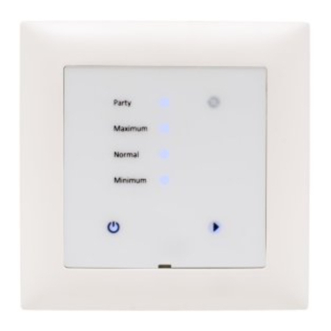
Featuring an attractive front panel that ts a Decora® type wall plate, SceneStation has a minimal
design that ts into the decor of most any project. SceneStation is available in White, Black, Ivory
or Almond color schemes with engravable button caps for optional labeling of the button functions.
RGB style LED backlighting behind each button can be customized to t different styles and needs.
Easy Installation
SceneStation was designed for easy installation. It ts neatly into a standard single-gang electrical
box and only requires two connections, one for power and one for DMX.
SceneStation’s power requirements are minimal and exible. The station can be powered by a 11 to
28 volt DC source (5W minimum), or a 14 to 28 volt AC source (5VA minimum).
If the station is connected to lighting xtures or another DMX controller, then the station requires a
DMX cable as well. If the station is being used exclusively as a wireless slave to one or more other
stations, then the DMX cabling is not needed.

6 | Introduction SceneStation Installation and Programming Guide

SceneStation Installation and Programming Guide Installation | 7
Installation
SceneStation is designed to be installed into either a standard single-gang electrical box for
Architectural applications or in our portable enclosure for temporary applications.
Architectural
For architectural installations, SceneStation is typically installed “in-wall” by use of a standard single-
gang electrical box. SceneStation is approximately the same size as a standard residential dimmer
switch (see specications for exact dimensions).
SceneStation comes with a two-piece designer wall plate that nishes the installation with a profes-
sional look that shows no visible hardware (screws). Multiple gang wall plates are also available. If
desired, SceneStation can also be mounted in a 3rd party Decora® style wall plate, however you
may need additional mounting screws if using your own wall plate.
Power for the station is supplied by a Class 2 transformer that provides between 11 to 28 volts DC
(5W minimum), or 14 to 28 volts AC (5VA minimum).
If the station is going to be used to output DMX to one or more lighting xtures, a suitable DMX cable
should be run from the station location to the rst DMX xture. Additional DMX xtures are daisy-
chained from the rst xture.
If the station requires a DMX input from another source, a separate DMX cable must be run from the
other controller to the station.
If the station is going to be used only as a wireless slave to another station, no DMX cabling is
required.
See the gure on the next page for a diagram of the typical wiring connections to SceneStation.

8 | Installation SceneStation Installation and Programming Guide
Recommended DMX-512 Cable Types
CAT5E or CAT6
White/Brown =DMX Ground (Black)
Orange =DMX Data - (Brown)
White/Orange =DMX Data + (Red)
Others =Unused
Belden 9842
Drain Wire =DMX Ground (Black)
Blue/White =DMX Data - (Brown)
White/Blue =DMX Data + (Red)
Orange/White =Unused
White/Orange =Unused
Other similar 100-120 ohm twisted-pair
RS-485 compatible computer
communication cable may be used.
Interactive Technologies, Inc.
5040 Magnolia Creek Drive
Cumming, GA 30028 USA
678-455-9019 (Phone) • 678-455-9071 (Fax)
www.interactive-online.com
Drawn By: Rob Johnston
Date: 11/20/2012
Checked: Rob Johnston
Scale: 1:1
Units: Millimeters [Inches]
Revision
B
D0316: SceneStation Typical Wiring Diagram
DMX-512 Port
DMX Ground (Black)
DMX Data - (Brown)
DMX Data + (Red)
Optional DMX Input
Connect to First DMX Fixture,
Dimmer or Power Supply. DMX
signals then daisy-chain through
each unit.
DMX Output
Optional input from DMX
console or controller.
Power Input
(Non-Polarized)
SceneStation
Model SS-305
Class 2 Power Supply
11-28 VDC (5W minimum)
14-28 VAC (5VA minimum)
Optional Remote Station
DMX Output
(optional)
One or more remote stations may
connect to a master station via
2.4GHz wireless link.
* See table for
recommended
DMX cable types.
DMX Input Note:
SceneStation uses a bi-directional DMX
Port for both DMX Input and Output. If no
Input DMX signal is detected, SceneStation
will output a DMX signal. If an Input signal
is detected (from another console or
controller), SceneStation will automatically
go into "passive" mode, which allows the
upstream controller to be in full control of
the DMX fixtures. SceneStation also uses
this mode to record DMX scenes from the
external source.
18-22 AWG
2-Conductor
Electrical Box
Power Supply
Power

SceneStation Installation and Programming Guide Installation | 9
Portable Enclosure
The SceneStation Portable Enclosure is useful for any application where portability and convenience
are required.
The Portable Enclosure houses a SceneStation and provides a DC power input jack for connect-
ing an AC Adaptor as well as both Male and Female 5-pin XLR connections for connection to DMX
networks.
The station itself is identical to the Architectural version, it just comes packaged as a self-contained,
ready to operate kit with convenient jacks pre-wired into the enclosure.

10 | Installation SceneStation Installation and Programming Guide

SceneStation Installation and Programming Guide Hardware Conguration | 11
Hardware Conguration
See the following sections on hardware congurations and dip switch settings for SceneStation.
Conguration Display
When a SceneStation is powered-on, it briey displays a scrolling rainbow pattern on its LEDs. After
about one second of this display, all of the LEDs settle on a single color before fading out. The color
that the station displays indicates the hardware conguration of the station. The following list shows
the possible congurations:
•All LEDs Red = Stand-Alone, Non-Wireless Model (SS-105)
(please note that this model is no longer available)
•All LEDs Green = Wireless Model (SS-205 or SS-305)
Dip Switch Settings
Nearly all station programming is performed via the optional wireless connection to the SceneStation
Studio software or through the infrared Programmer’s Remote. Therefore, there are very few hard-
ware settings that can (or need) to be set.
SceneStation has two banks of eight dip switches (16 switches in total) on the back of the station
that are used for setting hardware-level features and to change the default settings for the IR remote.
By default, all switches are set to the “OFF” position, except switches 1 & 2 on the left side
are “ON”.

12 | Hardware Conguration SceneStation Installation and Programming Guide
The function of each of the switches are described below:
Left Switch Bank Right Switch Bank
Left Switch Bank
•1: DMX Pull-Up - Enables a weak pull-up resistor on the DMX Data + line. By default, this
switch should be “ON”. This feature can by turned off if some other DMX source on the
line has its own pull-up resistor installed.
•2: DMX Pull-Down - Enables a weak pull-down resistor on the DMX Data - line. By default,
this switch should be “ON”. This feature can by turned off if some other DMX source on
the line has its own pull-down resistor installed.
•3: DMX Terminate - Enables a DMX termination resistor on the DMX port. This should only
be necessary when the SceneStation is at the end of a long line of DMX devices receiving
DMX data from another source. Normally, this is not required and should remain “Off”.
•4: DMX Output Only - When turned “On”, this switch disables the bidirectional DMX data
port, making SceneStation only able to output DMX. This function can be enabled if a
special circumstance requires that the station ignore DMX input. Normally, this switch
should remain “Off”.
•5: Reserved - This switch is currently unused. Leave in the “Off” position.
•6: Reserved - This switch is currently unused. Leave in the “Off” position.
•7: Reserved - This switch is currently unused. Leave in the “Off” position.
•8: Reserved - This switch is currently unused. Leave in the “Off” position.
12345678
ON
12345678
ON

SceneStation Installation and Programming Guide Hardware Conguration | 13
Right Switch Bank
•1: Reserved - This switch is currently unused. Leave in the “Off” position.
•2: User’s Remote Lock - When turned “On”, this switch disables the User’s Remote. This
setting can also be turned on or off by an option available in SceneStation Studio.
•3: Front-Panel Memory Lock - When turned “On”, this switch disables the ability for the
front-panel to take DMX snapshots or adjust fade times. This setting can also be turned
on or off by an option available in SceneStation Studio
•4: IR Memory Lock - When turned “On”, this switch disables the ability for the IR
Programmer’s Remote to edit the memory of the SceneStation. This setting can also be
turned on or off by an option available in SceneStation Studio.
•5: IR Direct Preset Codes - When turned “On”, this switch enables the “Direct Preset
Codes” feature. This feature enables additional IR codes that directly activate any of the
64 presets in the station. This setting can also be turned on or off by an option available in
SceneStation Studio.
•6, 7, 8: Pair With IR Remote - These three switches choose which remote IR code the
station will receive commands from. Use this setting to set specic remote controls to
operate only specic stations. This setting can also be chosen by an option available in
SceneStation Studio. The following table shows which combination of switches corre-
spond to which options:
6 7 8 Pair With Remote
OFF OFF OFF Remote Code 1
OFF OFF ON Remote Code 2
OFF ON OFF Remote Code 3
OFF ON ON Remote Code 4
ON OFF OFF Remote Code 5
ON OFF ON Remote Code 6
ON ON OFF All Remotes
ON ON ON No Remotes
Note: See Appendix A for instructions for changing the IR code used by the Programmer’s
Remote.

14 | Hardware Conguration SceneStation Installation and Programming Guide
Table of contents
Other Interactive Technologies Controllers manuals
