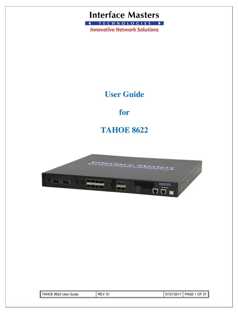
Interface Masters TAHOE 8824 User manual

Interface Masters Technologies Inc. Confidential & Proprietary
Tahoe 8824 User Guide
Rev: 01
09/15/2017
Page 1 OF 34
User Guide
for
TAHOE 8824

Interface Masters Technologies Inc. Confidential & Proprietary
TAHOE 8824 User Guide
Rev: 01
09/18/2017
Page 2 OF 34
CONTENTS
1. INTRODUCTION............................................................................................................ 6
1.1 Product Description ..................................................................................................... 6
1.2 Standard Features........................................................................................................ 6
1.3 Functional Diagram..................................................................................................... 7
1.4 Physical Layout for System .......................................................................................... 8
2. MAJOR COMPONENTS............................................................................................... 10
2.1 CN82xx/CN83xx –Processor..................................................................................... 10
2.2 DDR4 DRAM Controller............................................................................................ 11
2.3 eMMC......................................................................................................................... 12
2.4 SPI .............................................................................................................................. 13
2.5 SERDES - QLMs/DLMs ............................................................................................. 14
2.6 USB 3.0....................................................................................................................... 15
2.7 UART Interface........................................................................................................... 16
2.8 I2C Interface............................................................................................................... 17
2.9 SMI interface.............................................................................................................. 18
2.10 P Bus interface ......................................................................................................... 19
3 CPLD................................................................................................................................ 20
3.1 Access Interface.......................................................................................................... 20
3.2 LED Control............................................................................................................... 20
3.3 Boot Strap................................................................................................................... 20
3.4 Boot Devices............................................................................................................... 21
3.4.1 SPI NOR Flash..................................................................................................... 21
3.4.2 SD card ................................................................................................................ 21
3.4.3 eMMC................................................................................................................... 21
3.5 Selecting Boot Device................................................................................................. 21
4 ETHERNET PHYS............................................................................................................ 22

Interface Masters Technologies Inc. Confidential & Proprietary
TAHOE 8824 User Guide
Rev: 01
09/18/2017
Page 3 OF 34
4.1 VSC8221 –SGMII to 1000Base-T PHY................................................................ 22
4.2 VSC8257 –Quad XFI to SFI PHY........................................................................ 23
4.3 NVMe SSD............................................................................................................. 24
5 I2C PERIPHERALS.......................................................................................................... 25
5.1 I2C Bus 0 Peripherals........................................................................................... 25
5.1.1 DDR4 SPD......................................................................................................... 25
5.2.1 ADM1032ARZ - Temperature Sensor.................................................................. 26
5.2.2 MCP7940N - Real Time Clock............................................................................. 26
5.2.3 EEPROM.............................................................................................................. 26
6 IO MODULE..................................................................................................................... 27
7 POWER SUPPLY.............................................................................................................. 28
7.1 Power Consumption.............................................................................................. 28
7 COOLING FAN............................................................................................................. 29
8 ENCLOSURE................................................................................................................ 30
8 CUSTOMER SUPPORT................................................................................................... 31
8.1 Technical Assistance............................................................................................. 31
8.2 Life Support Policy................................................................................................ 31
8.3 Warranty ............................................................................................................... 32

Interface Masters Technologies Inc. Confidential & Proprietary
TAHOE 8824 User Guide
Rev: 01
09/18/2017
Page 4 OF 34
List of Figures
Figure 1. Tahoe 8824 Block Diagram............................................................................................ 7
Figure 2, DRAM controller Functional diagram ......................................................................... 11
Figure 3, TAHOE 8824 eMMC Interface..................................................................................... 12
Figure 4, TAHOE 8824 SPI Flash................................................................................................ 13
Figure 5, TAHOE 8824 USB 3.0 Diagram................................................................................... 15
Figure 6, TAHOE 8824 UART Interface...................................................................................... 16
Figure 7, TAHOE 8824 TWSI Interface ....................................................................................... 17
Figure 8, TAHOE 8824 SMI Interface Diagram.......................................................................... 18
Figure 9, TAHOE 8824 P Bus Functional Diagram.................................................................... 19
Figure 10, TAHOE 8824 CPLD Functional Diagram ................................................................. 20
Figure 11, TAHOE 8824 SGMII Interface ................................................................................... 22
Figure 12, TAHOE 8824 XFI to SFP interface............................................................................ 23
Figure 13, TAHOE 8824 NVMe Interface.................................................................................... 24
Figure 14, TAHOE 8824 I2C peripherals Diagram..................................................................... 25
Figure 15, TAHOE 8824 IO Module............................................................................................ 27
Figure 16, Cooling Fan Functional diagram............................................................................... 29

Interface Masters Technologies Inc. Confidential & Proprietary
TAHOE 8824 User Guide
Rev: 01
09/18/2017
Page 5 OF 34
List of Tables
Table 1, Boot Device Register ...................................................................................................... 21
Table 2, Boot Device Bits ............................................................................................................. 21
Table 3, Input Power Supply......................................................................................................... 28
Table 4, Output Power Supply...................................................................................................... 28
Table 5, Dimensions of TAHOE 8824 .......................................................................................... 30

Interface Masters Technologies Inc. Confidential & Proprietary
TAHOE 8824 User Guide
Rev: 01
09/18/2017
Page 6 OF 34
1. Introduction
1.1 Product Description
The TAHOE 8824 is a 1U network processing platform designed for enterprise
market. TAHOE 8824 is based on the Cavium 64-bit ARM technology. It supports
CN82xx/83xx family of processors. TAHOE 8824 features an optional swappable IO
module that supports either Eight ports of 10G or two ports of 40G.
1.2 Standard Features
•24 CN ARM64TM III processor cores. Core frequency up to 1.8GHz.
•72-bit of DDR4 memory with ECC
•4GB eMMC Interface
•SPI NOR Flash memory
•SD Card slot
•One M.2 NVMe SSD drives
•One on-board 1000Base-T Ethernet port
•Four on-board 10Gbps SFP+ ports
•Eight 10Gbps ports or two 40Gbps ports
•Two USB 3.0 Type A ports
•RJ45 RS232 serial port
•Four hot replaceable fans
•Two redundant hot swappable power supplies

Interface Masters Technologies Inc. Confidential & Proprietary
TAHOE 8824 User Guide
Rev: 01
09/18/2017
Page 7 OF 34
1.3 Functional Diagram
The below functional diagram of TAHOE 8824 Board.
Figure 1. TAHOE 8824 Block Diagram

Interface Masters Technologies Inc. Confidential & Proprietary
TAHOE 8824 User Guide
Rev: 01
09/18/2017
Page 8 OF 34
1.4 Physical Layout for System
Figure 2, Front view of TAHOE 8824
Figure 3, Top view of TAHOE 8824

Interface Masters Technologies Inc. Confidential & Proprietary
TAHOE 8824 User Guide
Rev: 01
09/18/2017
Page 9 OF 34
Figure 4, Side View of TAHOE 8824
Figure 5, Rear view of TAHOE 8824

Interface Masters Technologies Inc. Confidential & Proprietary
TAHOE 8824 User Guide
Rev: 01
09/18/2017
Page 10 OF 34
2. Major Components
2.1 CN82xx/CN83xx –Processor
The main CPU of the TAHOE 8824 is CN82xx/CN83xx, which is a multicore (up
to 24) CNARM64TM III processor that’s part of the Octeon TX family. The CN82xx has
one 72-bit DRAM controllers that can support DDR4, while the CN83xx has two
controllers. In addition, both CN82xx and CN83xx has several SERDES that can be
configured as various Ethernet interfaces, SATA and PCI-e.
The following is a list of interfaces that is provided by the CPU:
➢72-bit wide DDR4 module
➢eMMC Interface
➢SPI Interface
➢QLM SERDES blocks
➢Three DLM SERDES blocks
➢Two USB 3.0 host ports
➢Two UART Interface
➢Two TWSI bus (I2C)
➢Two SMI/MDIO bus
➢PBus (GPIOs)

Interface Masters Technologies Inc. Confidential & Proprietary
TAHOE 8824 User Guide
Rev: 01
09/18/2017
Page 11 OF 34
2.2 DDR4 DRAM Controller
The CN82xx support 72-bit DRAM interface controllers that can support DDR4 (up
to 2133 MT/s data rate) and the CN83xx has two. Each controller can support single-,
dual-, and quad-rank configurations.
The TAHOE 8824 support both DRAM controllers with a single DDR4 SODIMM
slot per controller. 16GB is the highest density SODIMM module available.
Figure 6, DRAM controller Functional diagram

Interface Masters Technologies Inc. Confidential & Proprietary
TAHOE 8824 User Guide
Rev: 01
09/18/2017
Page 12 OF 34
2.3 eMMC Interface
The CN83xx has an eMMC interface and it can support up to three attached eMMC
flash based memory devices with 3 CMD lines. The eMMC interface can operate at speeds
up to 52MHz. In addition, the memory device connected to the CMD0 and the SD card
slot is connected to CMD1, but a eMMC Boot Select Jumper can swap the CMD0 and
CMD1 lines to allow boot up from an SD card possible.
Figure 7, TAHOE 8824 eMMC Interface

Interface Masters Technologies Inc. Confidential & Proprietary
TAHOE 8824 User Guide
Rev: 01
09/18/2017
Page 13 OF 34
2.4 SPI Interface
The CN83xx has one SPI interface and can run with a clock speed of up to 50MHz.
The CN83xx can also boot from a SPI flash device as well. The maximum initial clock
speed during boot up is 12.5MHz.
The TAHOE 8824 has a SPI flash storage device attached and can be used as a boot
device when optioned to do so. By default, the eMMC flash is the boot device.
Figure 8, TAHOE 8824 SPI Flash

Interface Masters Technologies Inc. Confidential & Proprietary
TAHOE 8824 User Guide
Rev: 01
09/18/2017
Page 14 OF 34
2.5 SERDES - QLMs/DLMs
The CN82xx has three Quad Lane Modules (QLM) and three Dual Lane Modules
(DLM), while the CN83xx has four QLMs and three DLMs. Each QLM has four SERDES
and each DLM has two SERDES. Each QLM/DLM can independently be configured to
different high-speed Ethernet, PCI-e, or SATA interfaces.
The TAHOE 8824 will have the QLM/DLM configured as follows:
•QLM0 –PCI-e
•QLM1 –PCI-e
•QLM2 –Four XFI KR
•QLM3 –Four XFI KR or One XLAUI
•DLM4 –One SGMII
•DLM5 & DLM6 –Four XFI of One XLAUI (DLM5 & DLM6 are combined to
create a 4-lane interface)
➢QLM0 is configured as a PCI-e host interface and connect to a M.2 connector that
is meant for an NVMe SSD.
➢QLM1 is configured as a PCI-e host interface and is connected to the IO module
expansion slot for any PCI-e peripheral device.
➢QLM2 is configured as four XFI interface, which connect to a Quad XFI to SFI
PHY for the four on-board 10Gbps SFP+ ports.
➢QLM3, DLM5, & DLM6 are configured as eight XFI or two XLAUI interfaces to
connect to the Octal 10Gbps IO module or Dual 40Gbps IO module, respectively.
➢DLM4 is configured as an SGMII interface, that’s connected to an SGMII to
1000Base-T PHY to provide the Management Port.

Interface Masters Technologies Inc. Confidential & Proprietary
TAHOE 8824 User Guide
Rev: 01
09/18/2017
Page 15 OF 34
2.6 USB 3.0
The CN83xx has two USB 3.0 host interfaces and can support Super-Speed
(5.0Gbps), High-Speed (480Mbps), Full-Speed (12Mbps), and Low-Speed (1.5Mbps)
transmission rates.
The TAHOE 8824 has both interfaces exposed to the front panel as two USB 3.0 Type A
connectors.
Figure 9, TAHOE 8824 USB 3.0 Diagram

Interface Masters Technologies Inc. Confidential & Proprietary
TAHOE 8824 User Guide
Rev: 01
09/18/2017
Page 16 OF 34
2.7 UART Interface
The CN83xx has two UART interfaces.
The TAHOE 8824 has UART0 connected to a TTL to RS232 level translator,
which then connects to an RJ45 connector as the serial console. UART1 is exposed to an
internal header for factory debug use only.
Figure 10, TAHOE 8824 UART Interface

Interface Masters Technologies Inc. Confidential & Proprietary
TAHOE 8824 User Guide
Rev: 01
09/18/2017
Page 17 OF 34
2.8 I2C Interface
The CN83xx has two I2C interfaces that can each support standard mode (100kbps)
and fast mode (400kbps).
The TAHOE 8824 has TWSI0 connected to the DDR4 modules for the SPD and
TWSI1 connected to the TLV EEPROM, RTC, and temperature sensor.
Figure 11, TAHOE 8824 TWSI Interface

Interface Masters Technologies Inc. Confidential & Proprietary
TAHOE 8824 User Guide
Rev: 01
09/18/2017
Page 18 OF 34
2.9 SMI interface
The CN83xx has two MDIO interfaces that allows the CPU to manage Ethernet
PHYs. Both MDIO interfaces can support both Clause 22 and Clause 45 of the IEEE 802.3
standard.
The TAHOE 8824 has SMI0 connected to the on-board PHYs and SMI1 connected
to the IO module.
Figure 12, TAHOE 8824 SMI Interface Diagram

Interface Masters Technologies Inc. Confidential & Proprietary
TAHOE 8824 User Guide
Rev: 01
09/18/2017
Page 19 OF 34
2.10 PBus interface
The CN83xx has a general purpose parallel address/data bus interface called PBus.
The PBus has 32 address/data lines and can support up to eight connected devices with its
eight chip selects.
The TAHOE 8824 has the CPLD connected to the PBus and the PBus interface is
the main communication channel between the CPU and the CPLD.
Figure 13, TAHOE 8824 PBus Functional Diagram

Interface Masters Technologies Inc. Confidential & Proprietary
TAHOE 8824 User Guide
Rev: 01
09/18/2017
Page 20 OF 34
3 CPLD
The CPLD used in the TAHOE 8824 is an Altera MAX II CPLD. The main
purpose of the CPLD is to control power-up and reset sequencing, LED control, boot
strapping, and other miscellaneous glue logic.
Figure 14, TAHOE 8824 CPLD Functional Diagram
3.1 Access Interface
The main interface used to access the control registers of the CPLD is through the
CPU’s P Bus.
3.2 LED Control
All of the system LEDs will be driven by the CPLD and can be controlled by
software through the CPLD control registers.
3.3 Boot Strap
The hardware strap pins of the CN83xx are connected to the CPLD to allow the
user to easily change the boot media device by hardware jumper settings or by the CPLD
control registers for subsequent warm reboots.
Table of contents
Other Interface Masters Server manuals
Popular Server manuals by other brands
Axis
Axis 2400 - PHP3 GUIDE manual

PalatiumCare
PalatiumCare Palcare PAL-211401 Install manual
Dell
Dell PowerEdge 6800 Information update
Supero
Supero AS1021M-UR Plus user manual
IBM
IBM Enterprise Storage Server 2105 E10 Introduction and planning guide
Intel
Intel R2000BB series Quick installation user's guide
Sun Microsystems
Sun Microsystems Sun Fire X4250 Volume configuration guide
Snap Appliance
Snap Appliance Snap Server 510 Quick Start Guide and User CD
LEGRAND
LEGRAND CM2002 installation instructions
Lenovo
Lenovo ThinkServer RD550 Product guide
Perle
Perle IOLAN SDG4 TX Hardware installation guide
HP
HP D5970A - NetServer - LCII user guide
