Interface PCI-4142 User manual

USER’S MANUAL
PCI-4142
Ver. 1.2
URL:http://www.interface.co.jp

Notes to Users
The specifications of theproduct are under continuous improvement and while every effort is made to keep this
manual up-to-date, we reserve the right to update the contents of this user’s manual without prior notice. Therefore,
you should thoroughly read this user’s manual even if you have often purchased this product before.
Using this product requires technical knowledge of hardware and software.
Use this product only under the specified conditions such as power supply, voltage, temperature, and humidity range.
Interface Corporation’s products are not designed with components intended to ensure a level of reliabilitysuitable for
use under conditions that might cause serious injury or death.
Please consult our Technical Support Center (Contact information is listed below) if you intend to use our products
for special purpose, such as use for moving vehicles, medical treatment, aerospace engineering, controlling nuclear
power, submerged translators and so on. This product is made under strict quality management, however, when using
this product for the purposes that may result in any damages, lost profits, or any other incidental or consequential
damages resulting from breakdown of this product, the user is required to take adequate and appropriate measures,
such as installing safety devices to avoid possible serious accidents.
Conventions Used in This Manual
This icon denotes a warning, which advises you of precautions to take to avoid
injury, data loss, or system crash.
This icon denotes a note, caution, or warning.
Indemnification
Interface Corporation makes no warranties regarding damages resulting from installation or use of this product,
whether hardware or software, and assume that such risk reverts to the user.
Interface Corporation shall not be liable for any incidental or consequential damages, including damages or other
costs resulting from defects which might be contained in the product, product supply delay or product failure, even
if advised of the possibility thereof. Customer’s right to recover damages caused by fault or negligence on the part
of Interface Corporation shall be limited to the amount paid by the customer for that product.
This product including its software may be used only in Japan. Interface Corporation can not be responsible for the
use of this product outside Japan. Interface Corporation does not provide technical support service outside Japan.
Warranty
Interface Corporation products are warranted for a period of either one year or two years from the date of shipment, as
evidenced by receipts or other documentation. This warranty does not apply to the software products and expendable
supplies such as batteries.
Note: You can determine the warrantyperiod at our Web site by the serial number of your product. Those without
Internet access should contact the Sales Information Center.
During the warranty period Interface Corporation will, as a general rule, replace or recondition the defective product
without charge, in which case the user will berequired to pay the shipping costs, except as set forth below.
The Warranty provided herein does not cover expendable supplies such as batteries and damages, defects,
malfunctions, or failures caused by impact during transportation while under owner’s responsibility; owner’s failure to
follow the instructions and the precautions contained in this manual; modification and/or repair of the product by other
than Interface Corporation, trouble caused by use with peripherals not specified by Interface Corporation, power
failure or surges, fire, earthquake, tidal wave and/or flood.
This warranty applies only when the product is used in Japan.
Interface Corporation warrants its repairs for six months, and will again repair the same defective part without
additional charge provide the product is economically repairable. In that case, the user should attach a copy of the
most recent repair report to the repair request form. If no repair report is attached, it will be considered as a new repair
request.
Before You Export Interface Products
The foreign exchange and foreign trade law of Japan controls the export of this product, due to its possible use as a STRATEGIC
MATERIAL. Therefore, before you export this product, you must secure an export permit from the Ministry of Economy, Trade and
Industry of Japan.

PCI-4142 Ver. 1.2
-1- Interface Corporation
Revision History
Version Date Comments
1.0 March 2001 English version of user’s manual PCI-4142 published.
1.1 November 2002 Windows XP supported.
Hardware changed:
5 V card edge connector replaced with universal card edge connector.
Form factor of the PCI-4142 board changed.
Line driver/receiver changed.
Input: Changed from LTC487CS to MAX3491
Output: Changed from LTC489CS to MAX3491
Base clock frequency of 12.288 MHz added.
Manual revised:
Chapter 8 Version Considerations added.
Chapter 9 Appendix added.
Index added.
1.2 March 2003 Format is revised.
Due to constant product improvements, the information in this user’s manual is subject to change without prior
notice.

PCI-4142 Ver. 1.2
-Contents-
Interface Corporation -2-
Chapter 1 Introduction...............................................................................4
1.1 Packing List ..........................................................................................................................4
1.2 Using This Manual................................................................................................................4
1.3 Notes for Users.....................................................................................................................5
1.3.1 Cautions, Periodic Inspections, and Storage .........................................................5
1.4 Summary ..............................................................................................................................7
1.4.1 Features.................................................................................................................7
1.5 Optional Products .................................................................................................................8
1.5.1 Accessories............................................................................................................8
Chapter 2 Installation................................................................................9
2.1 General.................................................................................................................................9
2.2 Board Installation..................................................................................................................9
2.3 Driver Software Installation.................................................................................................10
2.3.1 Windows XP.........................................................................................................10
2.3.2 Windows 2000 .....................................................................................................10
2.3.3 Windows NT 4.0...................................................................................................11
2.3.4 Windows Millennium Edition ................................................................................11
2.3.5 Windows 98 .........................................................................................................11
2.3.6 Windows 95 .........................................................................................................12
2.4 Installation of DriverRelated Files.........................................................................................12
2.5 Software Uninstallation.......................................................................................................12
2.6 Board Uninstallation............................................................................................................12
Chapter 3 Hardware Configurations........................................................13
3.1 Factory Default Settings......................................................................................................13
3.2 Interface PCI Board Identification (RSW1)..........................................................................13
3.3 Access LED (LED1)............................................................................................................14
3.4 Transmit/Receive Data Monitor LED (SD1, SD2, RD1, RD2).............................................14
3.5 Signal Termination Setting (DSW1, DSW2)........................................................................14
3.6 Interrupt Sources ................................................................................................................15
3.6.1 Interval Timer.......................................................................................................15
Chapter 4 External Connections.............................................................16
4.1 Signal Definitions................................................................................................................16
4.1.1 Interface Product Pin Assignments (CN1, CN2) ..................................................16
4.1.2 Cable Connector..................................................................................................17
4.1.3 Signals.................................................................................................................17
4.2 Equivalent Circuits..............................................................................................................18
4.3 Example Connections.........................................................................................................19
4.3.1 Input Clock Selection ...........................................................................................20
4.3.2 Transfer Rates .....................................................................................................20
Chapter 5 Specifications.........................................................................21
5.1 Hardware Specifications.....................................................................................................21
Chapter 6 Software.................................................................................22
6.1 Summary ............................................................................................................................22
6.2 Operating Environment.......................................................................................................22
6.3 Program Composition.........................................................................................................22
6.4 Limitations ontheBaudRateGeneratorProgramming..............................................................23
6.5 Port Number Configuration.................................................................................................25
6.5.1 Serial Port Settings ..............................................................................................25
6.6 Utility Program ....................................................................................................................27
6.6.1 Required Items for the Utility Program.................................................................27
6.6.2 Checking Communications by Using a Computer Serial Port..............................27
Chapter 7 Troubleshooting......................................................................29
7.1 Checkpoints........................................................................................................................29
Chapter 8 Version Considerations..........................................................30
8.1 Hardware Version...............................................................................................................30
8.2 Correspondence Table .......................................................................................................30

PCI-4142 Ver. 1.2
Interface Corporation -4-
Chapter 1 Introduction
1.1 Packing List
The PCI-4142 board is shipped with the following items. When you open this kit, please verify that the material
you received matches the contents listed in the table below. If any items are missing or damaged, contact the
supplier from whom you bought this product.
Item Part Number Qty.
PCI Expansion Board
PCI-4142
1
Driver Software (CD-ROM)
GPF-4141
1
User’s Manual
PCI-4142
1
15-pin D-sub Male Connector 2
The following table summarizes the files installed after completing the software installation.
Contents
•Utility (Serial port terminal application)
•README.HTM file
•Driver software for Windows XP, Windows 2000, Windows NT 4.0, Windows Me, Windows 98, and
Windows 95
Notes:
•You should thoroughlyread the README.HTM file on the CD-ROM before using this product. It’s full
of the latest information.
•The warranty for this PCI-4142 is printed on the inside back cover of this manual.
1.2 Using This Manual
Together with the CD-ROM mentioned above (part number GPF-4141), this user’s manual provides all of the
essential information you need to install and use this PCI-4142. The CD-ROM contains the README.HTM
file. The README.HTM file contains instructions for matters requiring attention when you use the driver
software. Information on various topics can be found as shown in the chart below. Utilize the user’s manual in
conjunction with the README.HTM file.
TOPIC USER'S MANUAL README.HTM
Operating Environmental Specifications Included
List of Computers Verified and Validated Included
File List Included
Installation Included Included
Board Setup Included
Handling Precautions Included Included
Troubleshooting Included Included
Note: If you encounter problems, first consult the user’s manual and the README.HTM file. For more help,
visit our Interface Web site at http://www.interface.co.jp.

PCI-4142 Ver. 1.2
-5- Interface Corporation
1.3 Notes for Users
For your safety, follow all warnings and instructions described in this manual.
1.3.1 Cautions, Periodic Inspections, and Storage
Failure to follow these warnings may result in electric shock, burns, serious injury, and in some cases, even
cause death.
zKeep this PCI board away from flammable gases.
Use this product only under the conditions as shown below.
Environmental Specifications
Parameter Specification
Temperature Range 0 °C to 50 °C
Relative Humidity Range 20%to 90%(non-condensing)
Dust Typical office environment
Corrosive Gas None
Voltage Requirements +5 Vdc (±5%)
The following inspections should be carried out on this board periodically.
Periodic Inspections
Item Checkpoint
Cable Connections Be sure that all connectors and cables are installed correctly.
Card Edge Check for dirt or corrosion.
Connector Contacts Check for dirt or corrosion.
Board Surfaces Surface should be free of dust and foreign matter.
Warning!
!

PCI-4142 Ver. 1.2
Interface Corporation -6-
TO AVOID DAMAGE TO THE BOARD AND POSSIBLE INJURY, TAKE APPROPRIATE
PRECAUTIONS AS DESCRIBED BELOW WHEN HANDLING IT.
Caution!
!Use this product only under the conditions specified in 1.3.1. Failure to observe these precautions may
lead to malfunctions, board failure, and/or injury.
!Make sure the system is disconnected fromthe main power source before installing or removing any
boards and cables.
!Do not modify the board. Interface Corporation assumes no liability for any malfunctions resulting from
users’ unauthorized modification of the board.
!To avoid possible injury or malfunction, do not touch the goldfingers or the soldered surfaces of the
board.
!Take measures to avoid and minimize shock, vibration, magnetic fields, and static electricity in the
storage or operating environment of this board.
!This board should be stored exactly the same way as when it was received. Proceed as follows:
1. Put the board back in its electro-conductive bag.
2. Wrap the board with the original packing material.
3. Avoid excessive humidity.
4. Do not expose the board to the direct rays of the sun.
5. Store the board at room temperature.
This board has a detection circuit for insertion into and removal from a PCI slot. This
circuit allows the board to protect itself from incorrect operation such as inserting it into or
removing it fromthe PCI slot while the power is on. We call this feature Safety Bus.
!The Safety Bus doesn’t guarantee a successful Hot Swap.

PCI-4142 Ver. 1.2
-7- Interface Corporation
1.4 Summary
The PCI-4142 is an EIA RS-485 compliant asynchronous serial communications board for PCI-based
computers. It provides 2 communications channels and utilizes the ST16C654 UART (LSI 16550 functional
equivalent) including a programmable baud rate generator. This board incorporates surge suppressers to protect
signal lines from voltage surges. It supports the half-duplex and full-duplex communications.
1.4.1 Features
1. Maximum transfer rate: 921.6 kbps
The PCI-4142 supports the following base clock frequencies that are used for the serial communications
controller:
1.8432 MHz, 4.096 MHz, 4.9152 MHz, 7.3728 MHz, 8.0 MHz, 12.288 MHz, and 14.7456 MHz.
This feature allows you to select an appropriate transfer rate.
Please refer to “6.4 LimitationsontheBaudRateGeneratorProgramming,” page 23, for more details. This
board allows a transfer rate to be up to 921.6 kbps with 14.7456 MHzinput clock.
2. ST16C654 UART (LSI 16550 functional equivalent)
The PCI-4142 utilizes the ST16C654, functional equivalent with LSI 16550 (PC/AT compatibles standard
UART). This board provides 2 standard serial COM ports.
3. High-speed communication
The ST16C654 UART incorporates a 64-byte transmit FIFO and 64-byte receive FIFO per channel. This
feature provides you high-speed data transfer.
4. Half-duplex transmission and multi-drop network
The PCI-4142 supports half-duplex transmission and multi-drop network. In this case, you can connect up
to 32 terminals. (You need to install the BPC-0803 that supports the flow control and delimiter control to
extend the capability of communication ports. However, this is for Japanese environment only.)
5. Built-in timer/counter (The GPF-4141 doesn’t support this feature.)
The PCI-4142 has a timer/counter circuit that can be used as an interval timer. A software selectable clock
period of 10 µs, 100 µs, 1 ms, 10 ms, and 100 ms and a software programmable frequency divisor in the
range of 1 through 15 are supported. The output of the built-in timer/counter circuit can be used as an
interrupt source.
6. Surge suppressers
The PCI-4142 incorporates surge suppressers to protect signal lines from voltage surges. The protection
voltage range is -7 V to +12 V.
7. PCI 5 V/3.3 V signaling environment
The PCI-4142 is compliant with the PCI 5 V/3.3 V signaling environment.

PCI-4142 Ver. 1.2
Interface Corporation -8-
1.5 Optional Products
1.5.1 Accessories
Part Number Length Description
CAB-1705 5.0 m RS-485 crossover cable
This cable has a 15-pin D-sub male connector on each end. It connects a
15-pin board to 15-pin board or equipment.
CAB-1805 5.0 m RS-485 straight cable
This cable has a 15-pin D-sub male connector on each end. It connects a
15-pin board to 15-pin board or equipment.
COP-4142 A ten-pack of 15-pin male D-sub connectors
Connector catalog number: 17JE-23150-02(D8B) (DDK Ltd.)
Refer to our Web site for thelatest information and prices of optional products.
Connection Diagram CAB-1705
CAB-1805
COP-4142
15 pins
15 pins 15 pins
15 pins
15 pins
Connector: 10
CN1
CN2
PCI-4142
External device
Modem
Note: Inquire of Interface Corporation about non-standard length cables.

PCI-4142 Ver. 1.2
-9- Interface Corporation
Chapter 2 Installation
2.1 General
You need to install the device driver from the CD-ROM before getting started with this board. Installation
procedures differ dependingon which operating system is being used. Sections 2.3.1, 2.3.2, 2.3.3, 2.3.4, 2.3.5,
and 2.3.6 explain appropriate installation steps for Windows XP, Windows 2000, Windows NT 4.0,
Windows Me, Windows 98, and Windows 95, respectively.
2.2 Board Installation
1. Set the PCI board identification switch and any other switches correctly according to your system.
Refer to “Chapter 3 Hardware Configurations,” page 13, for more details.
2. Make sure that the computer is turned off and the power cord is unplugged. Remove the PC case cover and
a slot cover.
3. Insert the board into an open PCI slot.
<Example>
Insert the board into an open slot in your computer.
Board
Computer
PCI connector
Make sure that the goldfingers are
properly inserted into the PCI connector.
4. Screw in the bracket.
5. Replace the cover, plug in the power cord, and turn on the computer.

PCI-4142 Ver. 1.2
Interface Corporation -10-
2.3 Driver Software Installation
2.3.1 Windows XP
The driver may only be installed by a member of the System Administrators group.
1. When you log on to Windows XP, the device driver wizard will start automatically.
2. The Found New Hardware Wizard dialog box will appear, click Install froma list or specific location
[Advanced], and then click Next.
3. Insert the CD into your CD-ROM drive.
4. Click Search for the best driver in these locations, and select Search removable media
[floppy, CD-ROM...]. Then click Next.
5. Installation will start automatically.
6. Follow further instructions on your screen.
Make sure that there are no conflicts in setting up the computer resources, such as I/O addresses and interrupt
request levels.
2.3.2 Windows 2000
The driver may only be installed by a member of the System Administrators group.
1. When you log on to Windows 2000, the device driver wizard will start automatically.
2. In the Found New Hardware Wizard dialog box, click Next.
3. Click Search for a suitable driver for my device [recommended], and then click Next.
4. Select the Specify a location check box, and then click Next.
5. Insert the CD into your CD-ROM drive.
6. Click Browse and specify the \GPF4141\Win2000 folder on the CD, and then click OK.
7. To install the driver Windows found, click Next.
8. Follow further instructions on your screen.
Make sure that there are no conflicts in setting up the computer resources, such as I/O addresses and interrupt
request levels.

PCI-4142 Ver. 1.2
-11- Interface Corporation
2.3.3 Windows NT 4.0
The driver may only be installed by a member of the System Administrators group.
1. Log on to Windows NT 4.0.
2. Insert the CD into your CD-ROM drive.
3. Right-click the GPC4141.INF file in the \GPF4141\WinNT folder on the CD, and click Install on the
shortcut menu.
4. Follow further instructions on your screen.
Make sure that there are no conflicts in setting up the computer resources, such as I/O addresses and interrupt
request levels.
2.3.4 Windows Millennium Edition
1. When you log on to Windows Millennium Edition, the device wizard will start automatically.
2. Insert the CD into your CD-ROM drive.
3. In the Add New Hardware Wizard dialog box, click Automatic search for a better driver
[Recommended], and then click Next.
4. Follow further instructions on your screen.
Make sure that there are no conflicts in setting up the computer resources, such as I/O addresses and interrupt
request levels.
2.3.5 Windows 98
1. When you log on to Windows 98, the device wizard will start automatically.
2. Insert the CD into your CD-ROM drive.
3. In the Add New Hardware Wizard dialog box, click Search for the best driver for your device
[Recommended], and then click Next.
4. Select the Specify a location check box, and then click Browse.
5. Specify the \GPF4141\Win95 folder on the CD, and then click Next.
6. Follow further instructions on your screen.
Make sure that there are no conflicts in setting up the computer resources, such as I/O addresses and interrupt
request levels.

PCI-4142 Ver. 1.2
Interface Corporation -12-
2.3.6 Windows 95
1. When you log on to Windows 95, the device driver wizard will start automatically.
2. Insert the CD into your CD-ROM drive, and then click Next.
3. Click Other locations, and then click Browse.
4. Specify the \GPF4141\Win95 folder on the CD, and then click Finish.
5. When prompted to insert the CD, click OK.
6. In the Copy Files dialog box, click Browse.
7. Specify the \GPF4141\Win95 folder on the CD, and then click OK.
8. Follow further instructions on your screen.
Make sure that there are no conflicts in setting up the computer resources, such as I/O addresses and interrupt
request levels.
2.4 Installation of Driver Related Files
1. Insert the CD into your CD-ROM drive.
2. The installer will start automatically. If the installer doesn't start, run the SETUP.EXE file on the CD.
Select GPF-4141 in the list, and then click Install.
3. Follow further instructions on your screen.
4. To verify you have successfully installed the software package, check that Interface GPF-4141 is
registered in the Programs folder.
2.5 Software Uninstallation
1. Click the Start button, point to Settings and then click Control Panel.
2. Double-click Add/Remove Programs, and then click the Install/Uninstall tab.
3. Click Interface GPF-4141 in the list, and then click Add/Remove.
4. Follow further instructions on your screen.
2.6 Board Uninstallation
1. Make sure that your computer is turned off, and the power cord is unplugged from the AC outlet.
Remove the PC case cover.
2. Remove the screw from the board.
3. Remove the board from the slot, rocking it gently back and forth, being careful not to flex it.

PCI-4142 Ver. 1.2
-13- Interface Corporation
Chapter 3 Hardware Configurations
3.1 Factory Default Settings
Notes:
•If you own hardware version 12 of this board, refer to “Chapter 9 Appendix,” page 31.
•Refer to “Chapter 8 Version Considerations,” page 30.
CN1
CN2
SD1
RD1
SD2
RD2
RSW1
LED1 ON
DSW1 DSW2
ON
Item Description
CN1, CN2 15-pin D-sub female connector
DSW1 Terminator setting DIP switch (channel 1)
DSW2 Terminator setting DIP switch (channel 2)
LED1 Access LED
RD1 Receive data monitor LED (channel 1)
RD2 Receive data monitor LED (channel 2)
RSW1 Board ID rotary switch
SD1 Transmit data monitor LED (channel 1)
SD2 Transmit data monitor LED (channel 2)
3.2 Interface PCI Board Identification (RSW1)
RSW1
Rotary switch for Interface PCI board identification
(Factory default setting)
The rotary switch on each Interface PCI board is used to uniquely identify each board, in case multiple Interface
PCI boards of the same type are installed in the same system. Remember to set this switch on each board so as
not to conflict with any other of the same type. For every PCI-4142, PCI-4142P, or PCI-4142PE board in the
same system, the RSW1 rotary switch setting must be unique.

PCI-4142 Ver. 1.2
Interface Corporation -14-
3.3 Access LED (LED1)
The LED1 glows green to indicate I/O accesses are being generated by this board. A single access lights LED1
for 500 ms and when continual access ceases, it turns off 500 ms later.
3.4 Transmit/Receive Data Monitor LED (SD1, SD2, RD1, RD2)
The SD1 and SD2 LEDs glow green and the RD1 and RD2 LEDs glow red while the data is transferred.
Item Connector Channel Serial Output Pin LED
SD1 CN1 1
SD2 CN2 2 Low-level On
Item Connector Channel Serial Input Pin LED
RD1 CN1 1
RD2 CN2 2 Low-level On
3.5 Signal Termination Setting (DSW1, DSW2)
The DSW1 and DSW2 DIP switches set whether the terminators are enabled or disabled for channel 1 and
channel 2, respectively.
Setting Signal Description
ON
1234
(Factory default setting)
The signal is not terminated.
ON
1234
T
The signal is terminated.
ON
1234 The signal is not terminated.
ON
1234
(Factory default setting)
R
The signal is terminated.
ON
1234
(Factory default setting)
The signal is not terminated.
ON
1234
C
The signal is terminated.
ON
1234 The signal is not terminated.
ON
1234
(Factory default setting)
I
The signal is terminated.

PCI-4142 Ver. 1.2
-15- Interface Corporation
3.6 Interrupt Sources
This board can generate interrupts to the computer with the following sources:
•Interval timer interrupt
•UART interrupt
>> Received data available interrupt
>> Transmitter empty interrupt
>> Receiver line status interrupt
>> Modem status interrupt
3.6.1 Interval Timer
The interval timer can be used to generate an interrupt to the host computer every timer cycle. The timer cycle
period is given by the following equation: T= RATE ×CLK.
T: Timer cycle period
RATE: 1 through 15
CLK: 10 µs, 100 µs, 1 ms, 10 ms, 100 ms
This timer begins counting immediately after both RATE and CLK are programmed, and it will keep counting
until a stop instruction is issued.
Note: The GPF-4141 software doesn’t support the interval timer.

PCI-4142 Ver. 1.2
Interface Corporation -16-
Chapter 4 External Connections
Keep these important points in mind when connecting the board with external equipment.
FAILURE TO OBSERVE THESE IMPORTANT SAFETY PRECAUTIONS MIGHT RESULT IN
EXCESSIVE VOLTAGE IN THE PCI BOARD CIRCUITS, CAUSING AN ELECTRICAL FIRE,
WITH POSSIBLE OPEN FLAME AND SMOKE.
!Never connect an output signal on the board to any other output signals on the board and/or external
equipment.
!When you use this product under undesirable conditions, we recommend you to use a twisted-pair
cable to eliminate interference caused by noises.
!Do not apply voltage with surges less than or equal to -7 V or greater than or equal to +12 V to any
input/output pins.
!Never connect CN1 and CN2 to any signals other than the RS-485 standard.
!Keep the signal cable away from other equipment as far as possible to avoid electromagnetic
interference.
4.1 Signal Definitions
4.1.1 Interface Product Pin Assignments (CN1, CN2)
Connector catalog number:
17LE-13150-27(D4BB)A
(DDK Ltd.)
81
15 9
81
15 9
LED1 CN1 CN2
NC
T(A)
C(A)
R(A)
I(A)
NC
NC
SG
1
2
3
4
5
6
7
8
9
10
11
12
13
14
15
T(B)
C(B)
R(B)
I(B)
NC
NC
NC
NC: Not connected
Note: The screw size of the 15-pin D-sub male connector is M3.

PCI-4142 Ver. 1.2
-17- Interface Corporation
4.1.2 Cable Connector
Connector catalog number:
17JE-23150-02(D8B)
(DDK Ltd.)
4.1.3 Signals
Signal Description
Signal Pin Number Description
NC 1
T(A) 2 Transmit (A)
C(A) 3 Control (A)
R(A) 4 Receive (A)
I(A) 5 Indication (A)
NC 6
NC 7
SG 8 Signal ground
T(B) 9 Transmit (B)
C(B) 10 Control (B)
R(B) 11 Receive (B)
I(B) 12 Indication (B)
NC 13
NC 14
NC 15

PCI-4142 Ver. 1.2
Interface Corporation -18-
4.2 Equivalent Circuits
zOutput Signals: C, T
DSW
Output signal (B)
Output signal (A)
220 Ω
MAX3491
R
zInput Signals: I, R
220 Ω
MAX3491
Input signal (B)
51 kΩ
51 kΩ
4.7 kΩ
4.7 kΩDSW Input signal (A)
R
R
R
R
R
Note: Porality Consideration
Line A: Inverted (-)
Line B: Non-Inverted (+)
When you connect cables, make sure that the porality is correct.
Output signal
Input signal
A
B
B
A
RS-485 driver RS-485 receiver
Input signal
+
--
+
Output signal
Table of contents
Other Interface PCI Card manuals
Popular PCI Card manuals by other brands
WaveSplitter
WaveSplitter WST-UOT004 Operation manual
Sun Microsystems
Sun Microsystems Sun FastEthernet PCI Adapter Installation and user guide

Kvaser
Kvaser PCIcan Reference manual

National Instruments
National Instruments PXI Express NI PXIe-1073 user manual
Digitus
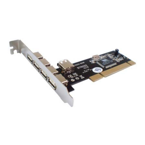
Digitus USB 2.0, 4+1 Port PCI Add-On card user manual
SENAO
SENAO 3054 PCI Aries user manual

