Interflex IF15x User manual

Installation and User Manual
Electronic Lock Cylinder IF15x

Copyright
Information in this documentation has been investigated and checked thoroughly in all
conscience. Nonetheless, errors cannot be excluded completely. Interflex Datensysteme
GmbH & Co. KG assumes no responsibility for the information in this manual, which is
subject to change without prior notice.
Interflex Datensysteme GmbH & Co. KG does not enter into any commitment.
Copyright © 2011
Printed on: 21.07.2011
Interflex Datensysteme GmbH & Co. KG
Ingersoll Rand Security Technologies
Zettachring 16
D-70567 Stuttgart
Germany
+49 (0711) 1322 0
Internet Email: info-interflex@eu.irco.com
Website: http://www.interflex.de
Ingersoll Rand’s Security Technologies Sector is a
leading global provider of products and services that
make environments safe, secure and productive. The
sector’s market-leading products include electronic
and biometric access control systems; time recording
and personnel scheduling systems; mechanical locks
and portable security; door closers and exit devices;
steel doors and frames; architectural hardware; and
technologies and services for global security markets.
Interflex is part of the Ingersoll Rand Security Technologies Sector.

Table of Contents i
Contents
Introduction 1
Short Description............................................................................................................................1
Scope of Delivery...........................................................................................................................2
Technical Data ...............................................................................................................................4
Installation/Dismantling 7
Installation of the Cylinder Body.....................................................................................................7
Installation of the Knob Module (with Disassembly Card)..............................................................7
Disassembly of the Knob Module (with Disassembly Card) ..........................................................8
Operation 9
Short-Time Release .......................................................................................................................9
Daily Release (Toggle Function)....................................................................................................9
Batteries 11
Battery Warning............................................................................................................................11
Low-Power Adapter......................................................................................................................13
Battery Change ............................................................................................................................14
Visual/Audible Signals 17
Index 21


1
Easy-to-install, highly flexible and yet safe – these are outstanding features of this state-of-
the-art electronic locking cylinder. With the IF15x series, you have purchased a cost-effective
and integratable solution.
Electronic identification media such as e. g. badges or easy-to-handle key tags are used as
"keys".
What else makes the Interflex locking cylinder second to none among its type: They
"communicate" with the access control systems IF6020 and IF6040. Utilize available
employee credentials and data stock from your access control systems. Conveniently
analyze the recorded data. Write complex settings to the locking cylinders in a convenient
way.
Short Description
IF 151 IF 152 IF 153
Double-knob locking
cylinder with one electronic
knob (brass, nickel-plated)
Double-knob locking
cylinder with two electronic
knobs (brass, nickel-plated)
Half cylinder with one
electronic knob (brass, nickel-
plated)
Standard length: 30/30mm
(lengths from 26/26 mm are
possible).
Standard length: 30/35mm
(lengths from 65 mm are
possible).
Standard length: 30/10mm.
The most important
components:
Electronic knob side
Mechanical knob side
Cylinder body
Fixing screw
Batteries
The most important
components:
Two electronic knob
sides
Cylinder body
Fixing screw
Batteries
The most important
components:
Electronic knob side
Cylinder body
Fixing screw
Batteries
C
HAPTER
1
Introduction

2 Introduction
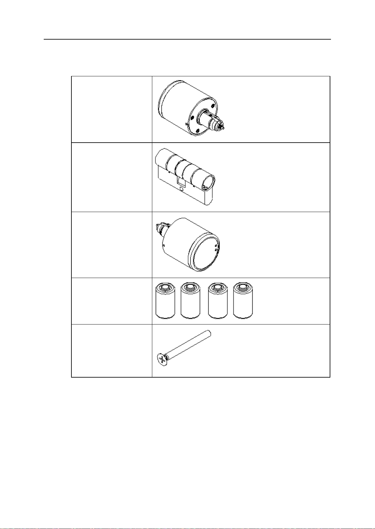
Scope of Delivery
Scope of Delivery IF151
Mechanical knob
Cylinder body
Knob module
Two batteries
Fixing screw
Introduction 3
Scope of Delivery IF152
Knob module
Cylinder body
Knob module
Four batteries:
Fixing screw

4 Introduction
Scope of Delivery IF153
Half cylinder body
Knob module
Two batteries
Fixing screw
Technical Data
Dimensions (in mm)
Cylinder Dimensions of the cylinder for Euro profile locks according to
DIN 18254
Electronic knob 40 × 41
Mechanical knob (only
IF 151) 29,5 × 20

Introduction 5
Power supply
Batteries Two lithium batteries per electronic knob, type CR2, 3 V
Battery life 10,000 actuations (approx.) at 20 °C, depending on the reader
type.
Storage life Four years (approx.)
Open when battery is
empty Possible at any time - external power source required (low-power
adapter).
Environmental conditions
Operating temperature 0 °C to 55 °C
Storage temperature -40 °C to 85 °C
Protection Category IP54 (IP standard, DIN EN 60529)
Installation location Indoor and outdoor areas (depending on product design). In the
event of use in outdoor areas, the general outdoor conditions must
be checked.
See also
Low-Power Adapter.......................................................................................13


7
Please note:
The cylinder is delivered fully preassembled.
On delivery, the knob module is in the factory state and must be programmed before
initial operation/installation. In this regard, see the Service Device instructions for use.
All of the described proceedings always relate to a programmed knob module.
In the version for Mifare transponders, the knob must be "woken up" by turning it on
before every step.
Installation of the Cylinder Body
Important: Before assembling the knob module, always check the freedom of movement of
all components.
Step 1: Remove the fixing screw and dismantle the existing cylinder body.
Step 2: Insert the cylinder body and secure it with the fixing screw.
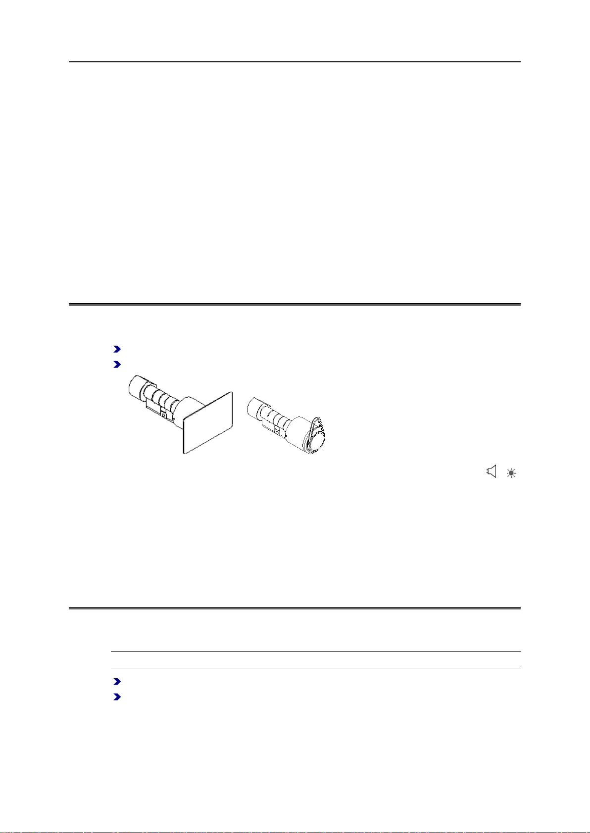
Installation of the Knob Module (with Disassembly
Card)
Step 1:"Wake up" the knob module by turning it.
Step 2: Hold the disassembly card in front of the knob module.
Knob module switches to disassembly mode.
Step 3: Insert the knob module into the cylinder body while turning it.
C
HAPTER
2
Installation/Dismantling

8 Installation/Dismantling
Step 4: Reset disassembly mode, i.e. hold the disassembly card or an authorized
credential in front of the knob module.
Disassembly of the Knob Module (with
Disassembly Card)
Step 1:"Wake up" the knob module by turning it on (if necessary).
Step 2: Hold the disassembly card in front of the knob module.
The knob module switches to disassembly mode.
Step 3:Turn the knob module until the emergency power contacts are in the 9 o'clock
position.
Step 4: Disassemble the knob by turning it back and forth slightly while simultaneously
pulling it gently.
9
For operation, appropriate credentials are required (transponder card, key or key tag).
The cylinder is delivered fully preassembled.
On delivery, the knob module is in the factory state and must be programmed before
initial operation/installation. In this regard, see the Service Device instructions for use.
All of the described proceedings always relate to a programmed knob module.
In the version for Mifare transponders, the knob must be "woken up" by turning it on
before every step.
Short-Time Release
"Wake up" the knob module by turning it.
Hold the authorized credential in front of the knob module.
or
A visual-acoustic signal sequence indicates that the knob module is in release mode ( /
green)).
After approx. 5 seconds, the knob module switches back to idle mode, i.e. it can be turned
"empty" again.
See also
Visual/Audible Signals...................................................................................17
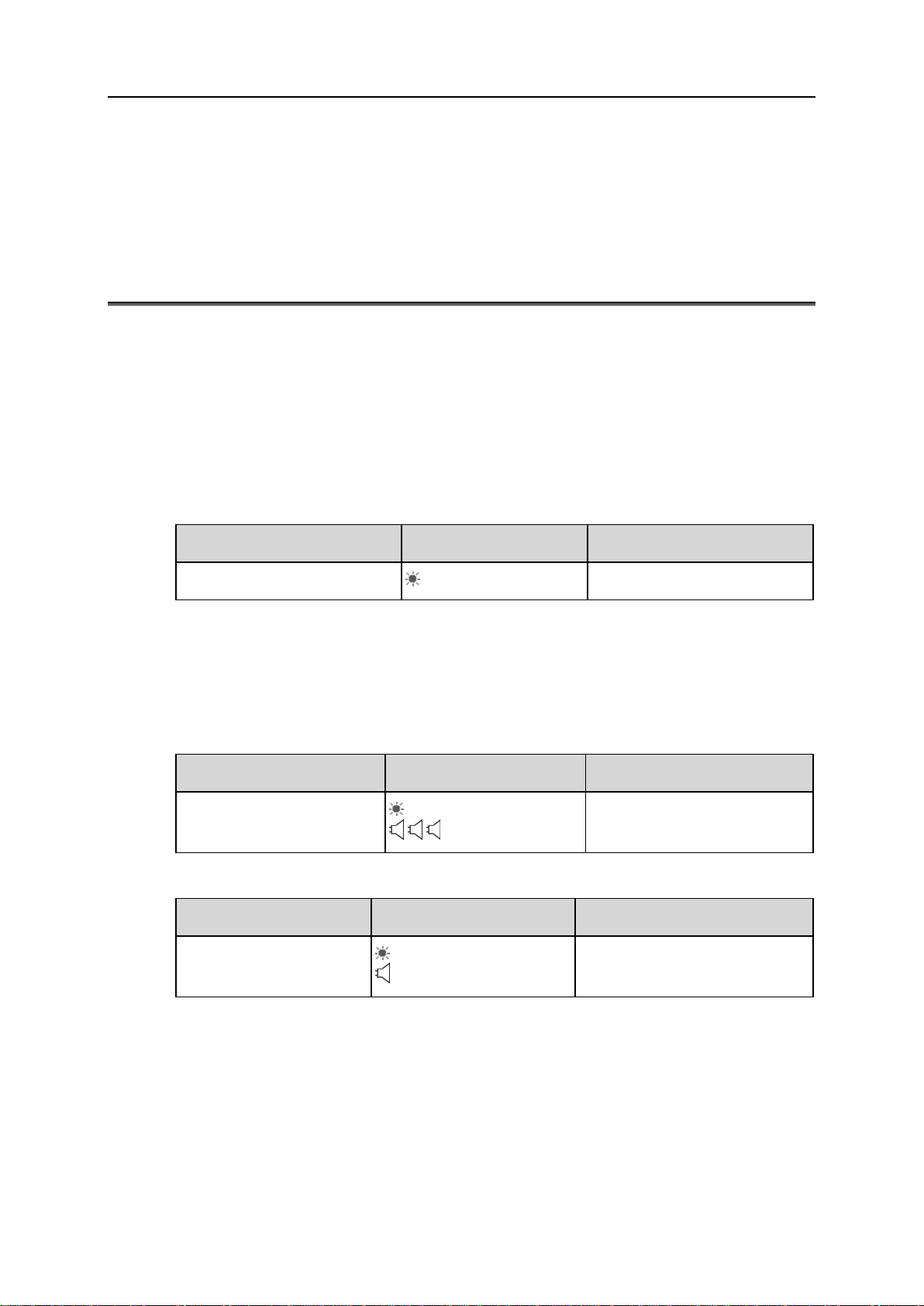
Daily Release (Toggle Function)
Please note: For this function, a credential with "Toggle Authorization" is required.
"Wake up" the knob module by turning it.
Hold the credential in front of the knob module until two visual-acoustic signal sequences
indicate that the locking cylinder is permanently released.
C
HAPTER
3
Operation

10 Operation
or
Signal sequence:
1 × (green) + 1 × .........(three seconds) .........1 × (green) + 1 ×
Warning: The locking cylinder is now permanently engaged, and the door can be opened
and closed without a credential.
To remove the toggle function, repeat the procedure.
See also
Visual/Audible Signals...................................................................................17
11
Battery Warning
Summary
Using visual and acoustic signals, the lock cylinder indicates that new batteries must be
used. You can recognize how urgently the batteries must be replaced with the following
signals:
Warning level 1 (only visible for administrators)
Time interval 1 ... Time interval 2 ... Time interval 3
Credential at knob ... (Red LED) ... Command execution.
Battery warnings of the early level 1 can only be seen by administrators for whom the service
flag is set on their credential.
Hint: If possible, change the battery at warning level 1. You thus prevent time-consuming
uncertainty and user questions when battery warnings occur.
Warning level 2
Time interval 1 ... Time interval 2 ... Time interval 3
Credential at knob ... (Red LED) ...
... Command execution.
Warning level 3
Time interval 1 ... Time interval 2 ... Time interval 3
Credential at knob ... (Red LED) ...
_____ (continuous tone) Command execution.
See also
Visual/Audible Signals...................................................................................17
C
HAPTER
4
Batteries

12 Batteries
Warning level 1
Warning level 1 is a very early warning level for administrators (such as the caretaker). For
these persons the service flag should be set on their credentials.
Credentials with the service flag set are otherwise the same as normal credentials; the
owners of these credentials will, however, receive an early warning that the batteries are low
(warning level 1) and can react accordingly.
Features
The following features are characteristic of warning level 1:
The red LED lights up 1 time briefly when you hold the credential to the knob.
Only after this delay time does the lock cylinder perform the desired action. It thus reacts
after a time delay.
Time interval 1 ... Time interval 2 ... Time interval 3
Credential at knob ... (Red LED) ... Command execution.
Action
Insert new batteries.
You thus prevent time-consuming uncertainty and user questions when the following battery
warnings (visible to the user) occur.
See also
Visual/Audible Signals...................................................................................17
Warning level 2
The following features are characteristic of warning level 2:
The red LED lights up 1 time (somewhat longer than in warning level 1).
You hear three short signal tones.
Only after this delay time does the lock cylinder perform the desired action. It thus reacts
after a time delay.
Time interval 1 ... Time interval 2 ... Time interval 3
Credential at knob ... (Red LED) ...
... Command execution.
Required action
Insert new batteries or contact the person responsible.
See also
Visual/Audible Signals.................................................................................. 17

Batteries 13
Warning level 3
The following features are characteristic of warning level 3:
Red LED lights up 1 time (longer than in warning level 2).
Long continuous tone.
The lock cylinder then performs the desired action. It thus reacts after a time delay.
Time interval 1 ... Time interval 2 ... Time interval 3
Credential at knob
... (Red LED) ...
_____ (long continuous tone) Command execution.
Required action
Immediately insert new batteries or contact the person responsible.
See also
Visual/Audible Signals.................................................................................. 17
Battery Change............................................................................................. 14
Low-Power Adapter
Using the low-power adapter, the knob module can be supplied with voltage externally at any
time, so that all functions can be performed, even if the batteries are empty.
Procedure
Insert the low-power adapter.
In doing so, ensure the correct alignment of the contact pins of the low-power adapters
towards the emergency power contacts of the knob module:
If the alignment is correct and the batteries are empty, an acoustic signal is heard.

14 Batteries
If necessary, align the contacts more accurately (when the adapter is inserted), i.e. grip
the knob module and turn the adapter slightly.
Battery Change
Important materials
Knob module
New batteries
Battery exchange card
Time card.
Procedure:
Step 1: "Wake up" the knob module by turning it on.
Step 2: Hold the battery replacement card in front of the knob module:
The knob module switches to battery replacement mode. The cover locking pins of the
knob module are unblocked.
Step 3: Push in the locking pins with the battery replacement tool simultaneously and
remove the cover:

Batteries 15
Step 4: Replace the batteries:
(if the polarity is incorrect, there is no signal)
Step 5 (for current firmware version no longer necessary): Repeat steps 1 and 2:
Step 6: Push in the locking pins and reattach the knob module cover:
Ensure that the locking pins engage correctly with the cover.
Step 7: Exit battery replacement mode, i.e. hold the battery replacement card or an
authorized credential in front of the knob module:
Step 8 (for current firmware version no longer necessary): Reset the time using the time
card.
See also
Visual/Audible Signals...................................................................................17

Table of contents


