manuals.online logo
Brands
  1. Home
  2. •
  3. Brands
  4. •
  5. Interlogix
  6. •
  7. Fire Alarm
  8. •
  9. Interlogix AS580 Assembly instructions

Interlogix AS580 Assembly instructions

© 2019 UTC Fire & Security Americas Corporation, Inc. 1 / 4 P/N 146145999-2 (EN) • REV E • ISS 28FEB19
AS580 Sounder with Level Installation Sheet
AS580 features
•Spirit level on top of the back plate to correctly align the
AS580
•Low profile polycarbonate box with the strobe lens
integrated into the lens
•Quick release cradle contains the PCB for easy servicing
•Highly weather resistant
•Easy wiring
•Easy diagnostics using the LEDs
•Two siren standard
•4.7 kΩ end of line (EOL) resistor built in
•Tamper switch to protect against removal of cover or
removal from surface
Mounting Instructions
Use the spirit level included on the back plate to correctly align
the AS580.
Make sure that the tamper switch is properly fitted.
AS580 LEDs
Table 1: LED modes
Jled link
LED mode
Not cut
LED flashes (1Hz)
Cut
LED on steady
If an alarm is caused by a power or tamper failure, the LEDs
will operate as follows: 1 LED on steady, 1 LED flashes.
The LEDs can be turned off by removing the four-wire
(male/female) connector.
Board layout
Figure 1: Board layout
Wiring the CSx75 control panel
Figure 2: Wiring the CSx75 control panel
Wiring the CS250, CS2512, CS234, and
CS245 control panels
Figure 3: Wiring the CS250, CS2512, CS234, and CS245 control
panels
Note: When the interconnection cable length exceeds 10 m,
program the siren tamper circuit as an isolated tamper loop
(Jtl jumper cut/open) and wire tamper pins TR and TL
individually to the CS panel:
•TR = CS250 pin 23
•TL = Aux. ground (GND)
2 / 4 P/N 146145999-2 (EN) • REV E • ISS 28FEB19
Wiring two AS580s together
Figure 4: Wiring two AS580s together
Wiring the CD34/CS450 control panel
Figure 5: Wiring the CD34/CS450 control panel
Wiring the CD95 control panel
Figure 6: Wiring the CD95 control panel
Wiring the CD72 control panel
Figure 7: Wiring the CD72 control panel
P/N 146145999-2 (EN) • REV E • ISS 28FEB19 3 / 4
Wiring the CS350 control panel
Figure 8: Wiring the CS350 control panel
Wiring the HKC control panel
Figure 9: Wiring the HKC control panel
Battery replacement or removal
Caution: Batteries can explode or cause burns
when incorrectly (dis)assembled or exposed to fire
or high temperatures.
Dispose of used battery according to battery directive
instructions and/or as required by local laws. Keep away from
children.
To replace batteries, disconnect the battery from the siren.
Only replace the battery with the recommended battery. Do not
use a different type of batteries. Use of any other batteries may
present a risk of fire or explosion.
Wiring the Advisor Advanced control panel
Figure 10: Wiring the Advisor Advanced control panel
Specifications
Voltage [1]
10.0 to 14.5 V (12 V nom.)
Standby current
LEDs off
LEDs on alt.
LEDs on cont.
38 mA
57 mA
74 mA
Operating current
(LEDs off) [2]
Sounder
Flash
Sounder + flash
350 mA
110 mA
420 mA
Sound output [2]
Average
Peak
112 dB(A) at 1 m
106 dB(A) at 3 m
119 dB(A) at 1 m
112 dB(A) at 3 m
Frequency
1.8 to 3 kHz
Sounder cut off timer
5 or 15 min
Working temperature
Without battery
With battery
−25 to +55°C
0 to +45°C
Dimensions
371 × 225 × 56 mm
Weight
1 kg
Recommended battery
BS120N-XXL 12 V lead-acid battery
Beacon
Operating current
110 mA
Light output
100.000 peak lumens
Life time
1.000.000 flashes
Flash rate
1 Hz
Spike suppression
network
Standard fitted
All values are typical values measured at 12 V.
[1] To be connected to an external current limited supply. We
recommend using a 5 A power supply.
[2] Using only one piezo saves 120 mA current consumption when
the sounder is activated (sound output will drop by 4 dB).
4 / 4 P/N 146145999-2 (EN) • REV E • ISS 28FEB19
Regulatory information
Manufacturer
PLACED ON THE MARKET BY:
UTC Fire & Security Americas Corporation, Inc.
3211 Progress Drive, Lincolnton, NC, 28092, USA
AUTHORIZED EU REPRESENTATIVE:
UTC Fire & Security B.V.
Kelvinstraat 7, 6003 DH Weert, Netherlands
Certification
Product warnings
and disclaimers
THESE PRODUCTS ARE INTENDED FOR SALE
TO AND INSTALLATION BY QUALIFIED
PROFESSIONALS. UTC FIRE & SECURITY
CANNOT PROVIDE ANY ASSURANCE THAT
ANY PERSON OR ENTITY BUYING ITS
PRODUCTS, INCLUDING ANY “AUTHORIZED
DEALER” OR “AUTHORIZED RESELLER”, IS
PROPERLY TRAINED OR EXPERIENCED TO
CORRECTLY INSTALL FIRE AND SECURITY
RELATED PRODUCTS.
For more information on warranty disclaimers and
product safety information, please check
https://firesecurityproducts.com/policy/product-
warning/ or scan the QR code.
European Union
directives
UTC Fire & Security hereby declares that this
device is in compliance with the applicable
requirements and provisions of the Directive
2014/30/EU and/or 2014/35/EU. For more
information see www.utcfireandsecurity.com or
www.interlogix.com.
2012/19/EU (WEEE directive): Products marked
with this symbol cannot be disposed of as
unsorted municipal waste in the European Union.
For proper recycling, return this product to your
local supplier upon the purchase of equivalent
new equipment, or dispose of it at designated
collection points. For more information see:
www.utcfssecurityproducts.eu/recycle/
This product may contain a battery that cannot be
disposed of as unsorted municipal waste in the
European Union. See the product documentation
for specific battery information. The battery is
marked with this symbol, which may include
lettering to indicate cadmium (Cd), lead (Pb), or
mercury (Hg). For proper recycling return the
battery to your supplier or to a designated
collection point. For more information see
www.utcfssecurityproducts.eu/recycle/
Contact information
www.utcfireandsecurity.com or www.interlogix.com
For customer support, see www.utcfssecurityproducts.eu

Other Interlogix Fire Alarm manuals

Interlogix ESL User manual

Interlogix

Interlogix ESL User manual

Interlogix ATS1210E Assembly instructions

Interlogix

Interlogix ATS1210E Assembly instructions

Interlogix FR 1100 Series Guide

Interlogix

Interlogix FR 1100 Series Guide

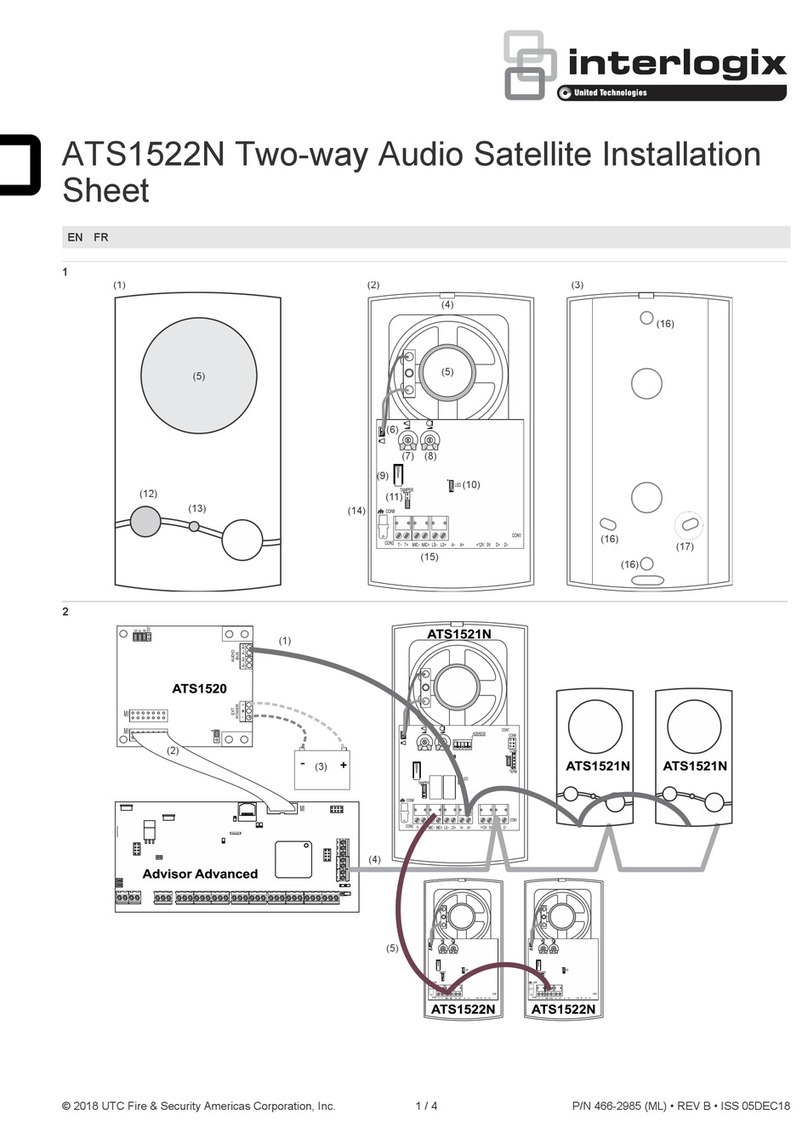
Interlogix ATS1522N Assembly instructions

Interlogix

Interlogix ATS1522N Assembly instructions

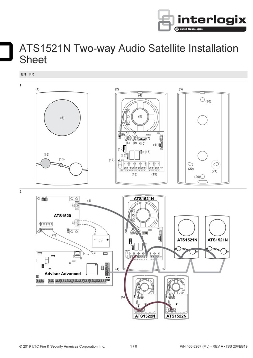
Interlogix ATS1521N Assembly instructions

Interlogix

Interlogix ATS1521N Assembly instructions

Popular Fire Alarm manuals by other brands

Autronica AutroSafe BS-3 manual

Autronica

Autronica AutroSafe BS-3 manual

Ei Electronics Ei2110H/8 User instructions

Ei Electronics

Ei Electronics Ei2110H/8 User instructions

Tyco RC-1 manual

Tyco

Tyco RC-1 manual

Fire-Lite Alarms MS-9200 Technical manual

Fire-Lite Alarms

Fire-Lite Alarms MS-9200 Technical manual

Kentec Electronics Taktis quick start guide

Kentec Electronics

Kentec Electronics Taktis quick start guide

Silent Alert SA3000 Technical manual

Silent Alert

Silent Alert SA3000 Technical manual

Edwards SB4U Installation sheet

Edwards

Edwards SB4U Installation sheet

Simplex 4098 Applications manual

Simplex

Simplex 4098 Applications manual

Gira 1141 Series Installation and operating instructions

Gira

Gira 1141 Series Installation and operating instructions

Simplex 4010ES Operator's manual

Simplex

Simplex 4010ES Operator's manual

Autronica BS-200 How to operate

Autronica

Autronica BS-200 How to operate

Hochiki America Corporation FireNET Plus Installation and operation manual

Hochiki America Corporation

Hochiki America Corporation FireNET Plus Installation and operation manual

Capstone CS-6000 Installation instruction

Capstone

Capstone CS-6000 Installation instruction

Fireboy- Xintex FBD-2 manual

Fireboy- Xintex

Fireboy- Xintex FBD-2 manual

Cooper Wheelock E50 installation instructions

Cooper Wheelock

Cooper Wheelock E50 installation instructions

Vighnaharta TSFC 12-2 user manual

Vighnaharta

Vighnaharta TSFC 12-2 user manual

Notifier NBG-12S installation manual

Notifier

Notifier NBG-12S installation manual

Hochiki IFD-E user manual

Hochiki

Hochiki IFD-E user manual

manuals.online logo
manuals.online logoBrands
  • About & Mission
  • Contact us
  • Privacy Policy
  • Terms and Conditions

Copyright 2025 Manuals.Online. All Rights Reserved.