Interlogix ATS1203(N) Assembly instructions

© 2019 UTC Fire & Security Americas Corporation, Inc. 1 / 24 P/N 1064130 (ML) • REV E • ISS 01JUL19
ATS1203(N)/ATS1204(N) 8 to 32 Zone DGP
with 3A Power Supply Installation Sheet
EN
DE
FR
IT
1
2
3
(1)
(2)
(3)
(3)
(4)
(5)
(6)
1740
ATS1201
1740
ATS CP
ATS1210
ATS1116
ATS1203
(1) (2)
(3)
(4)
(5) (6)
(7)
(3) (3)
(4) (4) (4) (4)
(5) (5)
(7)
(7)
(8)
(9)
(8)
(9) (9)

2 / 24 P/N 1064130 (ML) • REV E • ISS 01JUL19
4
(7)
(2) (7)
(1)
(5)
(4)
(3)
(6)
(8) (8)
(4)
(5)
(3)
(1)
(2)
(6)

P/N 1064130 (ML) • REV E • ISS 01JUL19 3 / 24
5
6
ATS120x V24 DGP
0-EXIT, Menu:
1-DGP status
0-EXIT, Menu:
Operating
*=-, #=+, 0-Exit
2-Input status
0-EXIT, Menu:
View Input State
Input No:
17, Normal, 113
*=-, #=+, 0-Exit
...
32, Open, 226
*=-, #=+, 0-Exit
3-DGP settings
0-EXIT, Menu:
1 DGP Address
*=Change, 0-Exit
Battery Load OFF
*=Change, 0-Exit
Mains Check ON
*=Change, 0-Exit
Extended mode
*=Change, 0-Exit
Static Outputs
*=Change, 0-Exit
4-Factory Reset
0-EXIT, Menu:
Factory Default
*=Yes,#=No:
EN: Installation Sheet
Description
The ATS1203(N)/ATS1204(N) provides zone expansion with 8
to 32 zones to ATS control panels with a built in power supply
of max. 3 A (total). Both the mains power supply and the
battery are monitored. The DGP also provides for 8 to 32
outputs occupying 2 DGP addresses when selected to support
more than 16 outputs.
The ATS1203(N)/ATS1204(N) functionality is similar to the
ATS1201.
Setup of the ATS1203(N)/ATS1204(N) is possible using the
built-in menu that can be accessed through Titan or the ATS
control panel menu 28.
Mains power connection
Use the mains connector terminal for connecting the mains-
supply. A fixed cable or a flexible mains leading to an earthed
mains outlet can be used. In case fixed wiring is used, insert a
dedicated circuit breaker in the power distribution network. In
all cases, the mains connection has to comply with local
regulations.
(1)(2) (3)
(4)
J15
YN
(5) J15
LOAD
()6
()7
()8
()9
()10
()11
()12 ()13 ()14 ()15
()16 ()17 ()18

4 / 24 P/N 1064130 (ML) • REV E • ISS 01JUL19
WARNING: Electrocution hazard. To avoid personal injury or
death from electrocution, remove all sources of power and
allow stored energy to discharge before installing or removing
equipment.
When installing the mains power, use a strain relief like cable
ties and coupling PG16’s to ensure proper wiring. In all cases,
local regulations should be applied.
Battery replacement
This product may contain one (or more) sealed, rechargeable,
BS-type lead-acid battery. Because removing the battery may
affect the product configuration settings or trigger an alarm,
only a qualified installer should remove the battery.
To remove a battery:
1. Make sure that your product settings allow you to open the
cover without starting the tamper alarm.
2. Switch off the mains power, if necessary, and remove the
cover.
3. Disconnect the battery, sliding the product's wires off the
wire connectors. Note that depending on the battery model
the connectors may be located differently.
4. Remove the battery from the holder.
Dispose of the battery as required by local ordinances or
regulations. See the specifications for your product or contact
technical support for information on replacement batteries.
Mounting
The unit is mounted with screws or bolts through the four
mounting holes in the base.
Ensure that the unit is mounted on a flat, solid, vertical surface
such that the base will not flex or warp when the mounting
screws/bolts are tightened.
Leave a 50 mm clearance between equipment enclosures
mounted side by side and 25 mm between the enclosure and
the sidewall.
The battery mounting facility inside the housing is only useful
for steady state use of the control panel. Remove the battery
for transport of the control panel.
Ensure that the wire terminals are isolated. Use tie wraps to
prevent contact with any other wires or circuits in case wires
break.
General installation guidelines
The ATS1203(N)/ATS1204(N) has been designed, assembled
and tested to meet the requirements related to safety, emission
and immunity with respect to environmental electrical and
electromagnetic interference, as of current relevant Standards.
If the following guidelines are followed, the system will give
many years of reliable service.
In addition to the following guidelines, during the installation of
the ATS1203(N)/ATS1204(N), it is essential to follow any
country dependent installation requirements of local applicable
standard. Only a qualified electrician or other suitable trained
and qualified person should attempt to wire this system to the
mains or to the public telephone network.
•Ensure that there is a good earth available for the alarm
system.
•Maintain a separation between the low voltage and mains
supply cables. Use separate points of cable entry to the
control panel cabinet.
•If the upper and/or lower cabinet entry cable holes are
used to route wiring into the control panel, always use a
proper pipe fitting system by means of an appropriate
conduit and junction box. For this purpose, use only
materials of suitable flammability class (HB or better).
•For mains power connection, use the mains connector
terminal either through a permanent wiring or a flexible
mains cable to an earthed mains outlet. Always use cable
ties to fix mains cable, at the dedicated fixing point
provided near the mains terminal connector.
- In case of permanent fixed wiring, insert an easily
accessible, dedicated bipolar circuit breaker in the power
distribution network.
- Never attempt to solder mains connection wires end
where they will be wired to the terminal connectors.
•Avoid loops of wire inside the control panel cabinet and
route cables so that they do not lie on top or underneath
the printed circuit board. The use of cable ties is
recommended and improves neatness of the wiring within
the box.
•The battery used with this unit, must be made of materials
of suitable flammability class (HB or better).
•Any circuit connected either directly to the on board relay
contact or to external relay contact through the on board
electronic output, must be of SELV (Safety extra low
voltage) operating circuit.
- Mains switching relay must not be fitted inside the control
panel cabinet.
- Always place a suppression diode (e.g. a 1N4001)
across the relay coil.
- Use only relay with good insulation between the contacts
and the coil.
•The minimum clearance between equipment closures is
50 mm (between equipment vents).
•Only use units in a clean environment and not in humid
air. Environmental requirements are given in “Technical
specifications” on page 7.
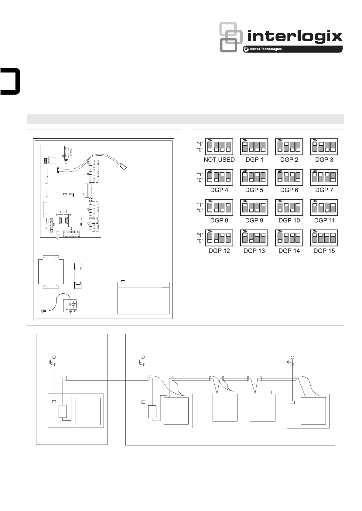
ATS1203(N)/ATS1204(N) housing
Figure 1: Housing layout
(1) Processor.
(2) NTC thermistor connection.
(3) Earth connection. Use also
for cable screen and lid of
box.
(4) Pry-off tamper mounting
location.
(5) Back-up battery.
(6) Mains power connection.
To conform to CEI 79-2 regulations at level 2, the use of the
pry-off tamper is mandatory (ST580 or ST590 kit).
Note: The pry-off tamper is not included with the product.
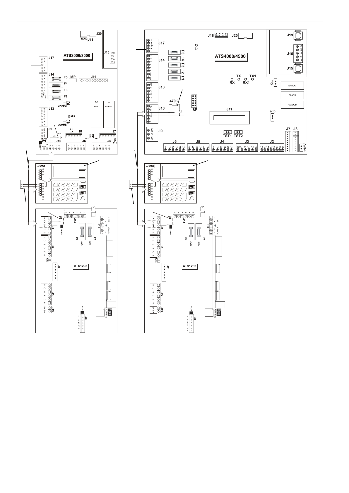
For detailed information on the PCB, see connection diagram.
NTC thermistor
See Figure 1, item 2.

P/N 1064130 (ML) • REV E • ISS 01JUL19 5 / 24
Take care that the NTC is positioned in free air far from the
heat sink or any other component. Its function is to measure
the batteries working temperature inside the cabinet. The
following table should be taken into account to measure the
charge voltage.
•15°C: 13.74 V
•20°C: 13.65 V
•25°C: 13.56 V
•30°C: 13.46 V
•35°C: 13.37 V
Measure the voltage at the battery terminal (Batt + and −) with
no battery attached.
Cabling ATS1203(N)/ATS1204(N)
Note: Preferred system databus wiring —see Figure 4. Refer
to the ATS control panel installation guide for a more detailed
description of the cabling.
The “TERM” link is on the first and last devices on the system
databus. In a “star” wiring configuration, the “TERM” link is only
fitted on the devices at the ends of the two longest system
databus cable runs.
Figure 4: System databus wiring
(1) TERM link fitted (first device on local databus).
(2) ATS control panel.
(3) ATS1105 LCD RAS (TERM switch not set to ON).
(4) Separate 12 V power supply. (Required if RAS is more than
100 m from the nearest panel or DGP. Connect “−” to “−” of the
databus).
(5) Preferred data cable type is WCAT 52 (2 pair twisted).
(6) TERM link fitted (last device on local databus).
(7) Earth connection to connect shield [1].
(8) Any data gathering panel like ATS1201, ATS1203, ATS1204,
ATS1210, ATS1220 or ATS125x.
[1] Connect cable shield to one device only.
See “System databus connection” below and “Earthing” below.
ATS1203(N)/ATS1204(N) connections
Figure 5: ATS1203(N)/ATS1204(N) connections
(1) 12 V battery
(2) System earth
(3) AC connection from
transformer
(4) Dipswitch to set DGP
address
(5) Battery load resistor jumper.
(6) Earth connection for cable
screens (shields)
(7) AC connection from
transformer and battery
power
(8) Clock-out Interface to plug
on output expansion or 4-
way non-clocked output
expansion (e.g. ATS1810).
(9) Link to select +12 VDC to
output board
(10) Auxiliary power supply
output
(11) Link to terminate databus
(12) Interface to ATS1202 input
expanders
(13) RS485 system databus &
box tamper connections
(14) Zones
(15) External siren
(16) System databus
(17) Normally closed pry-off
tamper contact
(18) Normally closed tamper
contact
(19) 1 kΩ resistor must be fitted
if external siren not
connected
(20) Normally closed panel
housing tamper contact
(21) Normally closed alarm
contact
(22) External 8Ω siren speaker
or siren
Notes
•If the battery load resistor is enabled, output 8 is no longer
available for non-clocked output expansion boards.
•The battery load resistor setting must correspond with
DGP programmed settings. See “Menu 3, DGP settings”
on page 7 for details.
•In case the DGP is set for 2 DGPs to enable all 32
outputs, the control panel programming should be set up
to poll the DGP address and the address + 1.
Links
•TERM: Termination of databus. Only to be used on first
and last device on the local databus.
•+12V: Connect +12 VDC to output board.
DGP DIP switch settings
See Figure 2.
Address: Select DGP address. Set switches 1 to 4 to OFF to
disable the DGP (see Figure 2 for correct address settings).
LEDs
•Tx: Red LED flashes when remote units (RAS and DGP)
are replying to polling.
•Rx: Yellow LED flashes when panel is polling remote
units. It must always be active.
System databus connection
The system databus is used to connect Data Gathering Panels
(to provide extra zones) and Arming Stations to the ATS
control panel. Remote devices can be up to 1.5 km from an
ATS control panel.
Arming Stations and Data Gathering Panels must be
connected via a 2 pair twisted shielded data cable from the
system databus connection. (WCAT 52 is recommended).
The shield of the data cable should be connected to earth at
the ATS control panel or any other earth point. However it
should be left disconnected at the other end.
It is recommended that where the distance between the arming
station and the nearest device is more than 100 meters, a
separate power supply be used to power the arming station.
To power the arming station, do not connect “+” from the
system databus. Connect “+” of the local power supply to “+”
on the arming station and connect 0 volts from the power
supply and 0 volts from the system databus to the arming
station terminal marked “−”.
See also “Cabling ATS1203(N)/ATS1204(N)” above.
Earthing
See Figure 3.
WARNING: Correct earthing procedures must be followed.
Earthing of one cabinet containing several devices
All devices designed for the system have earth connections via
metal studs to the metal housing. Take care, that these metal
studs make good connection to the housing (beware of paint).

6 / 24 P/N 1064130 (ML) • REV E • ISS 01JUL19
The earth connections of every piece of equipment in the
system can be used for connecting the shielding of shielded
cables. However: never connect the shield at both sides to
earth. If a device is placed in a plastic housing the earth lug of
this device does not have to be connected.
Earthing panels in a single building
In one building several cabinets or devices are earthen to
safety ground.
The safety earth of this building has to be checked by a
licensed contractor.
Earthing panels in more buildings
If the wiring extends to separate buildings, more than one
common earth system will be used. Use isolator/repeaters
ATS1740 to isolate the system databus. In this way the system
is protected against variations in earth potential.
Shielding
The shielding of all shielded cables used in the system should
only be connected at ONE side to one common earthing point
in a building (see Figure 3). If a shielded databus cable is
routed via more than one plastic device the shielding from
incoming and outgoing cable has to be connected.
Figure 3: System shielding example
(1) Building 1
(2) Building 2
(3) Mains power with local
earth
(4) Earth lug
(5) Mains power connector
(6) Advisor Master control
panel
(7) System databus
(8) Device in plastic housing
(9) Device in metal housing
Connecting the data gathering panel to a
control panel
Refer to the Advisor Master installation guide for instructions.
Zone and output numbering
Control panel
1 –16
DGP8
129 –144
DGP1
17 –32
DGP9
145 –160
DGP2
33 –48
DGP10
161 –176
DGP3
49 –64
DGP11
177 –192
DGP4
65 –80
DGP12
193 –208
DGP5
81 –96
DGP13
209 –224
DGP6
97 –112
DGP14
225 –240
DGP7
113 –128
DGP15
241 –256
Output numbering
A DGP can have a maximum of 16 outputs available as relays
or open collector outputs. The output numbers are the same as
the 16 zone numbers allocated to the DGP address.
The ATS1203(N)/ATS1204(N) can also support 32 outputs.
Enable this by selecting “2 DGP addresses” in menu 3 – “DGP
settings” (first option). Be aware that the ATS Control Panel
needs to be setup to poll both DGP addresses.
Note: If the battery load test resistor is enabled, output 8
follows the battery test (except when using clocked output
devices).
Zone numbering
The ATS1203(N)/ATS1204(N) has 8 zones that can be
expanded using the ATS 1202 (8 zones) to a maximum of
32 zones. If the number of zones exceeds 16, then the zones
are taken from the next DGP address and DGP ceases to
exist.
For example, DGP 1 has 24 zones (zones 17 to 40). The next
DGP in the system must now be addressed and polled as
DGP 3, because zones 33 to 40 on DGP 1 have been taken
from DGP 2.
The unused zone numbers in the system (zones 41 to 48)
must be programmed in the zone database as Type 0.
Programming the DGP
1. Polling the ATS1203(N)/ATS1204(N).
a. Enter menu 4 of the control panel installer menu, and
add the address for the device, then press ENTER.
b. Press ENTER, select the “DGP address” and press
ENTER again to enter the DGP details.
c. Select the device type 5 (ADVANCED DGP).
d. Press ENTER until you are back to the main menu.
Note: For more information on control panel programming,
see Advisor Master Programming Manual.
2. The ATS1203(N)/ATS1204(N) provides a menu through
which a number of options can be set. In addition the
status of the ATS1203(N)/ATS1204(N) itself or inputs can
be viewed. See Figure 6.
To enter the programming menu for the
ATS1203(N)/ATS1204(N):
a. Enter menu 28 of the control panel installer menu.
b. Press 1 ENTER followed by the DGP address selected
and ENTER to enter the DGP menu. The display now
shows “ATS1203” followed by the version number.
c. Press ENTER to proceed to the menu or press the
menu number followed by ENTER to go to a menu item
directly.
Menu 1, DGP status
This menu lists different types of information regarding
settings, DGP addresses to poll, inputs ranges, output ranges,
current consumption, etc. To view all data, enter the menu and
press ENTER to view the next item.
Menu 2, Input status
Shows the current status of all inputs that have been enabled
and the digital value of the status. The range that is available
can be viewed in the DGP Status. The input numbers used are
related to the address selected. See “Zone and output
numbering”.
To view the status, enter the first input to view. The selected
input status is shown. Press MENU to view the previous or
ENTER to view the next input.

P/N 1064130 (ML) • REV E • ISS 01JUL19 7 / 24
Menu 3, DGP settings
Menu 3 provides for some additional settings related directly to
the DGP functionality. Use the MENU key to change the
settings. Use ENTER to accept the settings and move to the
next item.
1. DGP configuration: selects the number of inputs and
outputs used. Available settings:
•1 DGP Address: Allows for max 16 inputs/outputs to be
connected. Shows as “DGP: n” where n is the selected
DGP address in menu 1, DGP status (Default setting)
•1 DGP+exp: Allows for max 32 inputs/16 outputs to be
connected. Shows as “DGP: n + exp” where n is the
selected DGP address in menu 1, DGP status.
•2 DGP Addresses: Allows for max 32 inputs/outputs to be
connected but requires DGP polling to be enabled for the
DGP address and the DGP address + 1. Shows as “DGP:
n + m” where n is the selected DGP address and m is the
address + 1 in menu 1, DGP status.
2. Battery load: Select if the battery load resistor should be
enabled on output 8. It will follow the battery test and add an
additional 68 Ω during the test. This option is required for
regulations (SKAFOR). Default is OFF.
Note: The setting must correspond with position of the battery
load resistor jumper (Figure 5, item 5).
3. Mains check: Enable/disable mains check. Set to OFF in
case no mains power supply is used to avoid mains fail being
reported. Default is ON.
4. Extended mode: To enable anti-mask detection it is
necessary to select Extended mode. Standard mode is needed
for backwards compatibility. Default is Extended mode.
5. Static outputs: Select whether to support static outputs
(max 8) or clocked outputs (max 32, depending on DGP
configuration). Default is Static outputs.
Menu 4, Factory reset
Use this menu to set all DGP configurations to default factory
settings.
Technical specifications
Mains power specifications
Mains Input Voltage (J17 –AC)
230 VAC 10%, 50 Hz 10%
Current consumption at 230V~
360 mA
Main board supply voltage
23 VAC typical
Power supply specifications
Power supply voltage
13.8 VDC 5%
Power supply current
2.9 A max. at 13.8 VDC 5%
Auxiliary Power output* (J14)
13.8 VDC 5%
For current see table below
Battery Power output (J17 –BAT)
13.8 VDC 5%.
For current see table below
Battery Type and max. capacity
Lead acid rechargeable 2 x
25 Ah 12 V nom. (BS129)
Main board consumption
75 mA at 13.8 VDC 5%
* Maximum permanent current to power devices external to the control
equipment in the absence of alarm conditions.
Available Aux/Battery current based on backup
Time (h)
Battery capacity (Ah)
Approval
Grade
Discharge
Charge
Output
7.2
18
25
36
50
Current (mA)
Incert
24
24
Aux
200
600
875
1200
1200
Battery
2525
2125
1850
1525
1525
EN 1&2
12
72
Aux
490
1300
1800
1800
1800
Battery
2235
1425
925
925
925
EN 3&4
60
24
Aux
40
220
330
500
550
Battery
2685
2500
2395
2225
2175
NF&A2P
36
30
Aux
110
360
550
850
1000
Battery
2615
2350
2200
1875
1725
NF&A2P
72
30
Aux
20
150
230
380
580
Battery
2700
2600
2500
2345
2100
VdS
30
24
Aux
150
500
700
1050
1100
B
Battery
2575
2225
2025
1675
1625
VdS
60
24
Aux
40
220
330
500
550
C
Battery
2685
2500
2395
2225
2175
General feature specifications
End of line resistor
(standard)
4.7 kΩ5% 0.25 W (2.2 kΩor 10 kΩ)
Standard on board output
Ext. siren (J13 —S+/S−)
Electronic output
Rating: 1 A at 13.8 VDC
Housing dimensions
ATS1203(N): 370 x 475 x 160 mm
ATS1204(N): 460 x 475 x 160 mm
Colour
Beige
Operating temperature
−10 to +55°C (certified +5 to 40°C)
Humidity
95% noncondensing
IP protection grade
IP30
Fuses
F4
Auxiliary
power & siren
F2 A, 20x5
F5
Battery
F3 A, 20x5
[1]
Mains fuse
ATS1203: Slow T –400 mA 20x5
ATS1203NN/ATS1204(N): Fast F–630 mA
20x5
[1] Mains fuse is part of the mains terminal block.
WARNING: Before removing the mains fuse, mains power
must be disconnected!
Regulatory information
Manufacturer
PLACED ON THE MARKET BY:
UTC Fire & Security Americas Corporation, Inc.
3211 Progress Drive, Lincolnton, NC, 28092, USA
AUTHORIZED EU REPRESENTATIVE:
UTC Fire & Security B.V.
Kelvinstraat 7, 6003 DH Weert, Netherlands

8 / 24 P/N 1064130 (ML) • REV E • ISS 01JUL19
Product warnings
and disclaimers
THESE PRODUCTS ARE INTENDED FOR SALE
TO AND INSTALLATION BY QUALIFIED
PROFESSIONALS. UTC FIRE & SECURITY
CANNOT PROVIDE ANY ASSURANCE THAT
ANY PERSON OR ENTITY BUYING ITS
PRODUCTS, INCLUDING ANY “AUTHORIZED
DEALER” OR “AUTHORIZED RESELLER”, IS
PROPERLY TRAINED OR EXPERIENCED TO
CORRECTLY INSTALL FIRE AND SECURITY
RELATED PRODUCTS.
For more information on warranty disclaimers and
product safety information, please check
https://firesecurityproducts.com/policy/product-
warning/ or scan the QR code.
Certification
UTC Fire & Security hereby declares that this
device is in compliance with the applicable
requirements and provisions of the Directive
2014/30/EU and/or 2014/35/EU. For more
information see www.utcfireandsecurity.com or
www.interlogix.com.
2012/19/EU (WEEE directive): Products marked
with this symbol cannot be disposed of as
unsorted municipal waste in the European Union.
For proper recycling, return this product to your
local supplier upon the purchase of equivalent
new equipment, or dispose of it at designated
collection points. For more information see:
www.recyclethis.info
Contact information
www.utcfireandsecurity.com or www.interlogix.com
For customer support, see www.utcfssecurityproducts.eu
DE: Installations Beschreibung
Anwendungsbereich
Die externe Meldegruppenerweiterung
ATS1203(N)/ATS1204(N) verfügt über 8 bis 32 Meldegruppen
zur Erweiterung der ATS-Einbruchmeldezentralen sowie über
ein integriertes Zusatznetzteil mit einer Leistung von max. 3 A
(insgesamt). Sowohl der Netzanschluss als auch die
Batterie(n) werden überwacht. Die AME verfügt außerdem
über 8 bis 32 Ausgänge, die 2 AME-Adressen belegen, wenn
mehr als 16 Ausgänge unterstützt werden.
Die Funktionen von ATS1203(N)/ATS1204(N) sind
vergleichbar mit denen von ATS1201.
ATS1203(N) und ATS1204(N) können über das integrierte
Menü eingerichtet werden, auf das über das Titan- oder das
ATS-Einbruchmeldezentralenmenü 28 zugegriffen werden
kann.
Netzanschluss
Verwenden Sie den Netzanschlussklemmenblock für die
Anschaltung der Erweiterung an das Stromnetz. Sie können
ein festes Kabel oder eine flexible Verbindung mit einer
geerdeten Netzsteckdose verwenden. Wenn eine feste
Verkabelung verwendet wird, muss die Anschaltung der
Netzspannung über eine getrennte Sicherung erfolgen. Die
jeweiligen Vorschriften des EVU's sind zu beachten! In allen
Fällen muss der Anschluss an die Stromversorgung mit den
lokalen Regelungen übereinstimmen.
WARNUNG: Gefahr von Stromschlägen. Entfernen Sie vor der
Installation oder Entfernung von Geräten alle Energiequellen
und warten Sie, bis die gespeicherte Energie entladen ist, um
Personenschäden oder Todesfälle durch Stromschläge zu
vermeiden.
Verwenden Sie bei der Installation des Netzanschlusses
Vorrichtungen wie Kabelbinder und PG16-Kabeleinführungen,
um die Belastung der Verkabelung zu verringern und eine
richtige Verkabelung zu gewährleisten. In jedem Fall müssen
lokale Regelungen Anwendung finden.
Batterie Ausbau/Entsorgung
Dieses Produkt kann eine (oder mehrere) versiegelte
wiederaufladbare BS-Typ Bleigelbatterie enthalten. Da ein
Ausbau der Batterie möglicherweise die Konfigurations-
einstellungen des Produkts beeinflussen könnte oder ein Alarm
verursachen könnte, sollte der Ausbau nur durch einen
qualifizierten Techniker vorgenommen werden.
Bei dem Ausbau der Batterie ist folgendes zu beachten:
1. Vergewissern Sie sich, dass Produkteinstellungen es
Ihnen ermöglichen das Gehäuse ohne Auslösung eines
Sabotagealarms zu öffnen.
2. Schalten Sie, wenn erforderlich die Netzspannung ab und
Öffnen Sie erst nachfolgend das Gehäuse.
3. Unterbrechen Sie Batterie von dem Gerät, indem Sie die
Anschlussleitungen von der Batterie abziehen. Bitte
beachten Sie, dass je nach Batteriemodel die
Anschlussklemmen der Batterie unterschiedlich
angeordnet sein können.
4. Entfernen Sie die Batterie von dem Stellplatz.
Für eine korrekte Wiederverwertung entsorgen Sie alle
Batterien gemäß den örtlichen Vorschriften. Beachten Sie bitte
die Spezifikationen Ihres Produkts oder kontaktieren Sie den
technischen Support für weitere Informationen zum Austausch
von Batterien.
Montage
Das Gerät wird mit Schrauben oder Bolzen befestigt, wobei die
vier Befestigungslöcher im Gehäuseunterteil zu verwenden
sind.
Sie müssen das Gerät auf einer ebenen, festen und vertikalen
Oberfläche befestigen, damit sich das Gehäuseunterteil nicht
verbiegt oder verzieht, wenn die Befestigungsschrauben oder -
bolzen angezogen werden.
Sehen Sie einen Freiraum von 50 mm zwischen den
nebeneinander montierten Gehäusen und von 25 mm
zwischen dem Gehäuse und der Seitenwand vor.
Der Batteriestellplatz innerhalb des Gehäuses ist nur nützlich
für die stationäre Verwendung der AME-Erweiterung. Nehmen
Sie die Batterie heraus, wenn Sie die Erweiterung
transportieren.
Vergewissern Sie sich, dass die Kabelanschlüsse isoliert sind.
Verwenden Sie Kabelbinder, um Kontakt mit anderen Kabeln
oder Kurzschlüsse beim Bruch von Kabeln zu vermeiden.

P/N 1064130 (ML) • REV E • ISS 01JUL19 9 / 24
Allgemeine Installationsrichtlinien
Die ATS1203(N)/ATS1204(N)-Erweiterung wurde so
entworfen, gefertigt und getestet, dass die Anforderungen an
Sicherheit, Emissionen und Unempfindlichkeit in Bezug auf
elektrische und elektromagnetische Interferenz erfüllt werden,
die gemäß den aktuellsten Normen gelten.
Wenn Sie die folgenden Richtlinien befolgen, wird das System
viele Jahre lang zuverlässig funktionieren.
Zusätzlich zu den folgenden Richtlinien ist es bei der
Installation der ATS1203(N)/ATS1204(N) wichtig, alle
landesspezifischen Richtlinien (VdS, BVD etc.) zu beachten.
Nur ein qualifizierter Techniker oder eine andere ausgebildete
und qualifizierte Person darf die Anschaltung an das Stromnetz
bzw. öffentliche Telefonnetz vornehmen.
•Vergewissern Sie sich, dass eine gute Schutzerdung für
das System verfügbar ist.
•Sorgen Sie für eine getrennte Kabeleinführung von
Netzkabel und Niederspannungskabeln. Verwenden Sie
hierzu die unterschiedlichen Kabelöffnungen des
Gehäuses.
•Wenn Sie die Kabeleinführungen oben bzw. unten am
Gehäuse nutzen, sind grundsätzlich passende
Anschlüsse, Leerrohre und Verteiler zu verwenden.
Verwenden Sie nur Material mit einer geeigneten
Brandschutzklasse (HB oder besser).
•Stellen Sie den Netzanschluss über die hierzu
vorgesehenen Klemmen und eine festverlegte Leitung
gemäß den jeweilig gültigen Vorschriften des EVU's her.
Für die Zugentlastung sichern Sie das Netzkabel mit
einem Kabelbinder an dem hierfür vorgesehenen
Befestigungspunkt neben den Anschlussklemmen. Für die
Zugentlastung sichern Sie das Netzkabel mit einem
Kabelbinder an dem hierfür vorgesehenen
Befestigungspunkt neben den Anschlussklemmen.
- Bei einem festverdrahteten Netzanschluss ist der
zugehörigen Verteilung ein leicht zugänglicher zweipoliger
Sicherungsautomat vorzusehen.
- Niemals die Kabelenden der Netzzuleitung durch
Weichlöten verzinnen, wenn diese unter die
Netzanschlussklemme geschraubt/geklemmt werden.
•Vermeiden Sie Kabelschleifen innerhalb des Gehäuses
und verlegen Sie Kabel so, dass sie nicht auf oder unter
den Leiterplatten liegen. Der Einsatz von Kabelbindern
erhöht die Übersichtlichkeit und wird daher empfohlen.
•Verwenden Sie nur Batterien, die aus einem Material
gefertigt wurden, welches einer geeigneten
Brandschutzklasse (HB oder besser) entspricht.
•Alle Komponenten, die entweder direkt an den
Relaiskontakten der Erweiterung oder über ein externes
Relais von den Transistor-Schaltausgängen der
Erweiterung direkt angesteuert werden, müssen eine
galvanische Trennung aufweisen und im
Niederspannungsbetrieb arbeiten.
- Relais, die Netzspannung schalten, dürfen nicht in das
Gehäuse der Erweiterung eingebaut werden.
- Schalten Sie eine Freilaufdiode (z.B. 1N4001) parallel
zur Spule des Relais.
- Verwenden Sie nur Relais mit ausreichender Isolierung
zwischen der Spule und den Schaltkontakten.
•Halten Sie einen Mindestabstand von 50 mm zwischen
dem Erweiterungsgehäuse und anderen Geräten
(Entlüftung) ein.
•Installieren Sie diese Geräte nur in sauberen
Räumlichkeiten ohne hohe Luftfeuchtigkeit.
Umgebungsanforderungen finden Sie in „Technische
Daten“ auf Seite 12.
ATS1203(N)/ATS1204(N) Gehäuse
Abbildung 1: Gehäuse-Layout
(1) Prozessor.
(2) NTC Thermistor Anschluß.
(3) Erdungsanschluss.
Verwenden Sie ihn auch für
die Kabelabschirmung und
Gehäusedeckel.
(4) Montagestelle für optionalen
Abreißkontakt.
(5) Notstrombatterie.
(6) Netzanschlussklemmblock.
Entsprechend den CEI 79-2-Regelungen der Klasse 2 ist die
Verwendung eines Abreißkontakts für die
Gehäuseüberwachung verpflichtend (Artikelnummer ST580
oder ST590).
Hinweis: Der Abreißkontakt für die Gehäuseüberwachung ist
nicht im Lieferumfang des Produkts enthalten.
Detaillierte Informationen zur Anschaltung finden Sie in der
Anschlussbelegung.
NTC Thermistor
Siehe Abbildung 1, Position 2.
Stellen Sie sicher, dass der NTC soweit wie möglich von dem
Kühlblech oder anderen Bauelementen angeordnet ist. Die
Funktion des NTC besteht in der Erfassung der
Arbeitstemperatur der Batterien. Die nachfolgende Tabelle
sollte bei der Messung der Ladespannung beachtet werden.
•15°C: 13.74 VDC
•20°C: 13.65 VDC
•25°C: 13.56 VDC
•30°C: 13.46 VDC
•35°C: 13.37 VDC
Messen Sie die Ladespannung an den Batterieanschlüssen
(batt+ und batt−) ohne angeschaltete Batterie.
Verkabelung von ATS1203(N)/ATS1204(N)
mit der Einbruchmeldezentrale ATS
Hinweis: Empfohlene Systemdatenbusverkabelung —siehe
Abb. 4. Eine detailliertere Beschreibung der Verkabelung
finden Sie im Installationshandbuch der ATS-
Einbruchmeldezentrale.
Die “TERM”-Steckbrücke wird auf den ersten und letzten
Geräten des Systemdatenbus aufgesteckt. Bei einer
sternförmigen Verdrahtung wird die “TERM”-Steckbrücke nur
an beiden leitungsentferntesten Geräten des Systemdatenbus
angebracht.

10 / 24 P/N 1064130 (ML) • REV E • ISS 01JUL19
Abbildung 4: System-Datenbus Verkabelung
(1) TERM-Brücke gesteckt (erstes Gerät am lokalen Datenbus).
(2) Einbruchmeldezentralen ATS.
(3) ATS1105 LCD BDT (TERM-Schalter nicht auf EIN eingestellt).
(4) Getrennte 12-V-Versorgung. (Erforderlich, wenn ein BDT weiter
als 100 m von der nächsten Einbruchmeldezentrale oder AME
entfernt ist. Verbinden Sie “−” mit “−” des Datenbusses.)
(5) Bevorzugter Datenkabeltyp ist WCAT 52 (Twisted Pair mit
2 Litzen).
(6) TERM-Brücke gesteckt (letztes Gerät am lokalen Datenbus).
(7) Erdungsanschlussklemme für Anschaltung der Abschirmung [1].
(8) Alle Erweiterungsbaugruppen, wie ATS1201, ATS1203N,
ATS1204N, ATS1210, ATS1220 oder ATS125x.
[1] Verbinden Sie die Abschirmung nur mit einem Gerät.
Siehe: „Systemdatenbusverbindung“ und „Erdung“ unten.
Verbindungsdiagramm
ATS1203(N)/ATS1204(N)
Abbildung 5: ATS1203(N)/ATS1204(N) Anschaltung
(1) Anschluss für 12-V-
Notstrombatterie(n)
(2) Systemerdung
(3) Wechselspannung vom
Transformator
(4) DIP-Schalter zum Einstellen
der AME-Adresse
(5) Batterie und Lastwiderstand
Steckbrücke.
(6) Erdungsanschluss für
Kabelabschirmungen
(7) Wechselspannungseingang
vom Transformator und
Batterieanschluss
(8) Getaktete Schnittstelle für
Anschluss einer Ausgangs-
erweiterung oder einer
nichtgetakteten 4-fach
Relaiserweiterung (z.B.
ATS1810).
(9) Steckbrücke für +12V
Gleichspannung mit
Ausgangserweiterung
(10) Nebenmelderversorgungs-
ausgang
(11) Steckbrücke zum
Abschließen des Datenbus
(12) Schnittstelle für ATS1202-
MG-Erweiterung
(13) RS485-Systemdatenbus &
Gehäusesabotage-
anschlüsse.
(14) Meldegruppen
(15) Externe Sirene
(16) System-Datenbus
(17) Normal geschlossener
Abreiß-Sabotagekontakt
(18) Normal geschlossener
Sabotagekontakt
(19) 1 kOhm-Widerstand muss
angebracht werden, wenn
die externe Sirene nicht
angeschlossen ist
(20) Normal geschlossener
Gehäuse-Sabotagekontakt
(21) Normal geschlossener
Alarmkontakt
(22) Externer 8-Ohm-
Sirenenlautsprecher oder
Sirene
Hinweis
•Wenn die Option “aktiver Batterietest” aktiviert ist, kann
der 8. Ausgang nicht mehr für nichtgetaktete
Ausgangserweitungsplatinen verwendet werden (diese
Option ist für SKAFOR Installationen relevant).
•Die Einstellung für den Batterie-Lastwiderstand muss den
in der AME programmierten Einstellungen entsprechen.
Siehe „Menü 3, AME-Einstellungen“ auf Seite 12 für
Details.
•Wenn die AME so eingerichtet ist, dass 2 AMEs alle
32 Ausgänge aktivieren, dann muss die Programmierung
der Einbruchmeldezentrale so angepasst werden, dass sie
die AME-Adresse und die AME-Adresse + 1 abfragt.
Steckbrücken
•TERM: Abschluss des Datenbusses. Wird nur am ersten
und letzten Gerät im lokalen Datenbus verwendet.
•+12V: +12 V Gleichspannung mit Ausgangserweiterung
verbinden
AME DIP-Schaltereinstellungen
Adresse: Wählen Sie die AME-Adresse. Stellen Sie die
Schalter 1–4 auf AUS, um die AME zu deaktivieren (Siehe
Abb. 2, um korrekte Adresseinstellungen zu erhalten).
LEDs
•Tx: Die rote LED blinkt, wenn abgesetzte Einheiten (BDT
und AME) auf die Abfrage antworten.
•Rx: Die gelbe LED blinkt, wenn die Zentrale die
abgesetzten Einheiten abfragt. Sie muss immer aktiv sein.
Systemdatenbusverbindung
Der Systemdatenbus wird verwendet, um die AME-
Erweiterungsbaugruppen (zum Bereitstellen zusätzlicher
Meldegruppen) und Schalteinrichtungen mit der ATS-
Einbruchmeldezentrale zu verbinden. Abgesetzte
Einrichtungen können bis zu 1.5 km von einer ATS-
Einbruchmeldezentrale entfernt installiert werden.
Die BDT-Schalteinrichtungen und AME-
Erweiterungsbaugruppen müssen über ein abgeschirmtes
Twisted Pair-Datenkabel mit 2 Litzen an die
Systemdatenbusverbindung angeschlossen werden (WCAT 52
wird empfohlen).
Die Abschirmung des Datenkabels sollte an der ATS-
Einbruchmeldezentrale oder einer anderen Erdungsmöglichkeit
geerdet werden. Das andere Ende sollte jedoch nicht
angeschlossen werden.
In Fällen, in denen der Abstand zwischen der Schalteinrichtung
und dem nächstgelegenen Gerät mehr als 100 Meter beträgt,
empfiehlt es sich, ein separates Netzteil zur
Spannungsversorgung der BDT-Schalteinrichtung zu
verwenden.
Um die Schalteinrichtung mit Spannung zu versorgen, dürfen
Sie nicht „+“vom Systemdatenbus anschließen. Verbinden Sie
„+“des lokalen Netzteils mit „+“auf der Schalteinrichtung, und
schließen Sie 0 Volt vom Netzteil und 0 Volt vom
Systemdatenbus an die mit „−„ markierte Klemme auf der
Schalteinrichtung an.
Siehe auch „Verkabelung von ATS1203(N)/ATS1204(N) mit
der Einbruchmeldezentrale ATS“ oben.
Erdung
Siehe Abb. 3.
WARNUNG: Die korrekten Erdungsprozeduren müssen
eingehalten werden.
Erdung eines Gehäuses mit mehreren Geräten
Alle systembezogenen Geräte/Erweiterungen weisen
Bolzen/Kabelschuhstecker am jeweiligen Gehäuse auf.
Vergewissern Sie sich, dass diese Bolzen/Stecker eine gute
Erdverbindung zum Gehäuse aufweisen und nicht mit Farbe
bestrichen werden. Stellen Sie sicher, dass diese metallischen
Anschlusspole eine gute Verbindung mit dem Gehäuse
aufweisen (achten Sie dabei auf die Lackierung).
Die Erdungsanschlüsse jedes Geräts des Systems sind für
die Anschaltung des Schirmbeidrahts geeignet. Falls
ein/e Gerät/Erweiterung in einem Kunststoffgehäuse

P/N 1064130 (ML) • REV E • ISS 01JUL19 11 / 24
verwendet wird, ist die Anschaltung des Erdungsanschlusses
nicht erforderlich. Aber: Verbinden Sie niemals die beiden
Enden der Abschirmung mit der Erdung. Wenn sich ein Gerät
in einem Kunststoffgehäuse befindet, muss die Erdungsnase
dieses Geräts nicht angeschlossen werden.
Erdung von Erweiterungen in einem Gebäude
Innerhalb eines Gebäudes werden die Gehäuse verschiedener
Geräte an einem geeigneten Erdungspunkt angeschaltet.
Die Güte der Schutzerde ist durch eine geeignete Fachfirma zu
prüfen.
Erdung von Erweiterungen in verschiedenen Gebäuden
Falls sich die Verkabelung des Systems über mehrere
Gebäude erstreckt, erfolgt die Erdung zwangsweise über mehr
als einen gemeinsamen Erdungspunkt. Verwenden Sie in
diesem Fall zur Isolation des System-Datenbus die ATS1740
Isolatoren/Repeater. Durch diese Baugruppen wird Ihr System
gegen mögliche Potenzialunterschiede geschützt. Auf diese
Weise ist Ihr System gegen unterschiedliche
Erdungspotentiale geschützt.
Abschirmung
Die Schirmbeidrähte aller abgeschirmten Leitungen des
Systems dürfen nur an EINEM gemeinsamen Erdungspunkt in
einem Gebäude (siehe Abb. 3) angeschaltet werden. Wird der
Systemdatenbus durch mehrere Geräte mit Kunststoffgehäuse
geführt, müssen die Schirmbeidrähte der ankommenden und
abgehenden Leitung miteinander verbunden werden.
Abbildung 3: Beispiel System-Abschirmung
(1) Netzanschluss mit lokaler
Erdung
(2) Netzanschlussklemme
(3) Systemdatenbus
(4) Erdungsanschlussklemme
(5) Gebäude 1
(6) Gebäude 2
(7) Gerät in Metallgehäuse
(8) Gerät in Kunststoffgehäuse
(9) Einbruchmeldezentralen
ATS
Verbinden der Erweiterungsbaugruppen mit einer
Einbruchmeldezentrale
Anweisungen zu diesem Thema finden Sie im
Installationshandbuch der Einbruchmeldezentrale.
Nummerierung von Meldegruppen und
Ausgängen
EMZ
1 –16
AME8
129 –144
AME1
17 –32
AME9
145 –160
AME2
33 –48
AME10
161 –176
AME3
49 –64
AME11
177 –192
AME4
65 –80
AME12
193 –208
AME5
81 –96
AME13
209 –224
AME6
97 –112
AME14
225 –240
AME7
113 –128
AME15
241 –256
Ausgangzuweisungen
Eine AME kann maximal 16 Ausgänge als Relais oder Open-
Collector-Ausgänge zur Verfügung stellen. Die
Ausgangsnummern stimmen mit den 16
Meldegruppennummern überein, die der AME-Adresse
zugeordnet wurden.
Die ATS1203(N)/ATS1204(N) können auch 32 Ausgänge
unterstützen. Dies können Sie aktivieren, indem Sie im Menü 3
„AME-Einstellungen“die erste Option „2 AME-
Adressen/Erweiteret AME“auswählen. Denken Sie daran,
dass Sie in der ATS-Einbruchmeldezentrale einrichten
müssen, dass beide AME-Adressen abgefragt werden.
Hinweis: Wenn die Option „Aktiver Batterietest“im Menü
AME-Einstellungen eingeschaltet wird, ist der 8. Ausgang fest
dem internen Batterietest zugewiesen (außer wenn getaktete
Ausgangsmodule verwendet werden).
Meldegruppennummerierung
Die ATS1203(N)/ATS1204(N) verfügen über 8 Meldegruppen,
die unter Verwendung der ATS1202-Erweiterung
(8 Meldegruppen) auf maximal 32 Meldegruppen erweitert
werden können. Wenn die Anzahl der Meldegruppen 16
übersteigt, dann werden die Meldegruppen von der nächsten
AME-Adresse übernommen und die AME existiert nicht länger.
z.B. AME 1 hat 24 Meldegruppen (Meldegruppen 17 bis 40).
Die nächste AME im System muss jetzt als AME 3 adressiert
und abgefragt werden, da die Meldegruppen 33 bis 40 der
AME 1 von AME 2 übernommen wurden.
Die nicht verwendeten Meldegruppennummern im System
(Meldegruppen 41 bis 48) müssen in der
Meldegruppendatenbank als Typ 0 programmiert werden.
Programmierung der AME
1. Abfrage der ATS1203/1204
a. Begeben Sie in das Menü 4 der
Zentralenprogrammierung und tragen Sie hier die Adresse
der AME ein. Betätigen Sie die ENTER Taste
abschliessend.
b. Betätigen Sie ENTER, wählen Sie die „AME-Adresse“
und betätigen Sie ENTER erneut um zu den AME-Details
zu gelangen.
c. Wählen Sie nun den AME-Typ 5 (Erweiterte-AME).
d. Betätigen Sie erneut ENTER bis Sie sich wieder im
Hauptmenü befinden.
Hinweis: Weitere Informationen bezüglich der
Zentralenprogrammierung entnehmen Sie bitte dem ATS-
Zentralen Programmierhandbuch.
2. Die ATS1203(N)/ATS1204(N) stellen ein Menü zur
Verfügung, über das eine Reihe von Optionen eingestellt
werden können. Außerdem kann der Zustand von
ATS1203(N)/ATS1204(N) oder der Eingänge angezeigt
werden. Siehe Abb. 6.
So öffnen Sie das Programmiermenü für
ATS1203(N)/ATS1204(N):
a. Öffnen Sie Menü 28 im Errichtermenü der
Einbruchmeldezentrale.
b. Drücken Sie 1 ENTER, geben Sie dann die gewählte
AME-Adresse ein und drücken Sie ENTER, um das AME-
Menü zu öffnen. Auf dem Display wird “ATS1203” und
nachfolgend die Versionsnummer angezeigt.
c. Drücken Sie ENTER, um das betreffende Menü
anzuzeigen, oder geben Sie die Menünummer ein und
drücken Sie ENTER, um eine Menüoption direkt
aufzurufen.

12 / 24 P/N 1064130 (ML) • REV E • ISS 01JUL19
Menü 1, AME-Status
In diesem Menü werden verschiedene Arten von Informationen
angezeigt, welche die Einstellungen betreffen, die
abzufragenden Adressen, MG-Zuweisung, Ausgangs-
Zuweisung, Stromaufnahme etc. Um alle Daten anzuzeigen,
öffnen Sie das Menü und drücken Sie ENTER, um den
nächsten Eingang anzuzeigen.
Menü 2, Eingangsstatus
Zeigt den aktuellen Status aller aktivierten Eingänge sowie den
digitalen Wert des Status an. Im AME-Status kann der
verfügbare Bereich angezeigt werden. Die verwendeten MG-
Nummern hängen mit der ausgewählten Adresse zusammen.
Siehe “Nummerierung von Meldegruppen und Ausgängen.”
Um den Status anzuzeigen, geben Sie die erste anzuzeigende
Meldegruppe ein. Der ausgewählte MG-Status wird angezeigt.
Drücken Sie auf MENU, um den vorherigen anzuzeigen, oder
auf ENTER, um die nächste MG anzuzeigen.
Menü 3, AME-Einstellungen
Menü 3 bietet einige zusätzliche Einstellungen, die direkt mit
der AME-Funktion zusammenhängen. Die Einstellungen
können Sie mit der Taste MENU ändern. Mit ENTER
übernehmen Sie die Einstellungen und bewegen sich zum
nächsten Element.
1. AME-Konfiguration: Wählt die Anzahl der verwendeten MG
und Ausgänge aus. Verfügbare Einstellungen:
•1 AME-Adresse: Erlaubt den Anschluss von maximal
16 MG / Ausgängen. Wird als „AME: n“angezeigt, wobei n
die im Menü 1 „AME-Status“ausgewählte AME-Adresse
ist (Standardeinstellung).
•1 AME + Erw: Erlaubt den Anschluss von maximal 32 MG
/ 16 Ausgängen. Wird als „AME: n + Erw“angezeigt,
wobei n die im Menü 1 „AME-Status“ausgewählte AME-
Adresse ist.
•2 AME-Adressen: Erlaubt den Anschluss von maximal
32 MG/Ausgängen, erfordert aber, dass die AME-Abfrage
für beide AME-Adressen aktiviert wird (Adresse und
Adresse + 1). Wird als „AME: n + m“angezeigt, wobei n
die im Menü 1 „AME-Status“ausgewählte AME-Adresse
ist und m die Adresse + 1.
2. Batterielastwiderstand: Wählen Sie aus, ob der Batterie-
Lastwiderstand am 8. Ausgang aktiviert werden soll. Er wird
während des Batterietests einen internen 68 Ohm Widerstand
zuschalten. Diese Option ist gemäß den SKAFOR-Vorschriften
erforderlich. Standard ist AUS.
Hinweis: Die Einstellung muss der Steckbrücken-Position des
Batterie-Lastwiderstands entsprechen (Abbildung 5, Punkt 5).
3. Netzprüfung: Aktiviert/deaktiviert die Netzprüfung Stellen
Sie die Prüfung aus, wenn keine Netzversorgung verwendet
wird, um zu verhindern, dass Netzfehler übertragen werden.
Standard ist EIN.
4. Erweiterter Modus: Um die Anti-Mask Detektion zu
ermöglichen, ist es erforderlich den Erweiterten Modus zu
aktivieren. Der Standard Modus ermöglicht die Abwärts-
Kompatibilität, der Auslieferungszustand ist der Erweiterte
Modus.
5. Statische Ausgänge: Wählen Sie aus, ob statische
Ausgänge (max. 8) oder getaktete Ausgänge (max. 32,
abhängig von der AME Konfiguration) unterstützt werden.
Standard ist 'Statische Ausgänge'.
Menü 4, Zurücksetzen auf Werkseinstellungen
In diesem Menü können Sie alle AME-Einstellungen auf die
Werkseinstellungen zurücksetzen.
Technische Daten
Spezifikationen Netzspannung
Netzspannung (J17 − AC)
230 V Wechselspannung 10%, 50 Hz
10%
Stromaufnahme bei 230V~
360 mA
Versorgungsspannung der
Hauptleiterplatte
23 V Wechselspannung (typisch)
Netzteil Spezifikationen
Versorgungsspannung
Netzteil
13.8 V Gleichspannung 5%
Stromabgabe Netzteil
2.9 A max. bei 13.8 V Gleichstrom 5%
Nebenmelderversorgungs-
ausgang [1] (J14)
13.8 V Gleichspannung 5% Siehe
Tabelle unten für Stromstärke
Batterie Spannungsausgang
(J17 − BAT)
13.8 V Gleichspannung 5% Siehe
Tabelle unten für die Berechnung der
Batteriekapazität / Stromabgabe
Batterietyp und max.
Kapazität
Aufladbare Blei-Gelbatterie
2 x 25 Ah 12 V nom. (BS129)
Stromaufnahme der
Erweiterung
75 mA bei 13.8 V Gleichspannung 5%
[1] Maximale Dauerstromabgabe für die Versorgung von externen
Baugruppen im Nicht-Alarmfall.
Verfügbare Nebenmelderversorgung bei Netzausfall
Zeit (h)
Batteriekapazität (Ah)
Zulassungs-
klasse
Entladung
Ladung
Ausgang
7.2
18
25
36
50
Stromabgabe (mA)
Incert
24
24
Nebenmelder
200
600
875
1200
1200
Batterie
2525
2125
1850
1525
1525
EN 1&2
12
72
Nebenmelder
490
1300
1800
1800
1800
Batterie
2235
1425
925
925
925
EN 3&4
60
24
Nebenmelder
40
220
330
500
550
Batterie
2685
2500
2395
2225
2175
NF&A2P
36
30
Nebenmelder
110
360
550
850
1000
Batterie
2615
2350
2200
1875
1725
NF&A2P
72
30
Nebenmelder
20
150
230
380
580
Batterie
2700
2600
2500
2345
2100
VdS
30
24
Nebenmelder
150
500
700
1050
1100
B
Batterie
2575
2225
2025
1675
1625
VdS
60
24
Nebenmelder
40
220
330
500
550
C
Batterie
2685
2500
2395
2225
2175

P/N 1064130 (ML) • REV E • ISS 01JUL19 13 / 24
Allgemeine Feature-Spezifikationen
Abschlusswiderstand
(Standard)
4.7 kΩ5% 0.25 W (2.2 kΩ oder 10 kΩ)
Standardmäßiger
Onboard-Ausgang
Ext. Sirene (J13 - S+/S−)
Elektronischer Ausgang
Belastbarkeit: 1 A bei 13.8 V
Gleichspannung
Gehäuseabmessungen
ATS1203N: 370 x 475 x 160 mm
ATS1204N: 460 x 475 x 160 mm
Farbe
Beige
Umgebungsbedingungen
VdS Umweltklasse 2
VdS-Anerkennung
G 106022
Betriebstemperatur
−10 bis +55°C (zertifiziert +5 bis 40°C)
Luftfeuchtigkeit
95% max. (nicht kondensierend)
IP-Schutzgrad
IP30
Sicherungen
F4
Nebenmelderversorgung &
Sirene
F2 A, 20x5
F5
Batterie
F3 A, 20x5
[1]
Netzsicherung
ATS1203: Slow T –400 mA 20x5
ATS1203N/ATS1204(N): Fast F –
630 mA 20x5
[1] Die Netzsicherung ist Bestandteil der Netz-Anschlussklemmleiste.
WARNUNG: Vor dem Entfernen der Netzsicherung muss die
Netzspannung abgeschaltet werden!
Rechtliche Hinweise
Hersteller
INVERKEHRBRINGER:
UTC Fire & Security Americas Corporation, Inc.
3211 Progress Drive, Lincolnton, NC, 28092, USA
BEVOLLMÄCHTIGTER EU REPRÄSENDANT:
UTC Fire & Security B.V.
Kelvinstraat 7, 6003 DH Weert, Niederlande
Produktwarnungen
und Haftungs-
ausschluss
DIESE PRODUKTE SIND FÜR DEN VERKAUF
AN UND DIE INSTALLATION DURCH
QUALIFIZIERTES PERSONAL VORGESEHEN.
UTC FIRE & SECURITY ÜBERNIMMT
KEINERLEI GEWÄHRLEISTUNG DAFÜR, DASS
NATÜRLICHE ODER JURISTISCHE
PERSONEN, DIE UNSERE PRODUKTE
ERWERBEN, SOWIE „AUTORISIERTE
HÄNDLER“ ODER „AUTORISIERTE
WIEDERVERKÄUFER“ ÜBER DIE
ERFORDERLICHE QUALIFIKATION UND
ERFAHRUNG VERFÜGEN, UM
BRANDSCHUTZ- ODER
SICHERHEITSTECHNISCHE PRODUKTE
ORDNUNGSGEMÄSS ZU INSTALLIEREN.
Weitere Informationen zu Haftungsausschlüssen
sowie zur Produktsicherheit finden Sie unter
https://firesecurityproducts.com/policy/product-
warning/, oder scannen Sie den QR-Code.
Zertifizierung
VdS
VdS-Anerkennung:G 106022
Umweltklasse: Geprüft nach VdS Umweltklasse 2
UTC Fire & Security erklärt hiermit, dass dieses
Gerät den geltenden Anforderungen und
Bestimmungen der Richtlinie 2014/30/EU
und/oder 2014/35/EU entspricht. Für weitere
Informationen siehe www.utcfireandsecurity.com
oder www.interlogix.com.
2012/19/EU (WEEE): Produkte die mit diesem
Symbol gekennzeichnet sind, dürfen nicht als
unsortierter städtischer Abfall in der europäischen
Union entsorgt werden. Für die korrekte
Wiederverwertung bringen Sie dieses Produkt zu
Ihrem lokalen Lieferanten nach dem Kauf der
gleichwertigen neuen Ausrüstung zurück, oder
entsorgen Sie das Produkt an den
gekennzeichneten Sammelstellen. Weitere
Informationen hierzu finden Sie auf der folgenden
Website: www.recyclethis.info
Kontaktinformationen
www.utcfireandsecurity.com oder www.interlogix.com
Kontaktinformationen für den Kundendienst finden Sie unter
www.utcfssecurityproducts.de
FR: Instructions d'installations
Que fait il?
L’ATS1203(N)/ATS1204(N) est un DGP 8 zones / 16 sorties
extensible à 32 zones / 16 sorties pour les centrales ATS avec
chargeur intégré 3 A max et supervision secteur et batterie. Ce
DGP peut également gérer jusqu’à 32 sorties si il a été
paramétré comme gérant plus de 16 sorties.Il occupera alors
l’emplacement de deux DGPs.
Les fonctions de l’ATS1203(N)/ATS1204(N) sont identiques à
celle de l’ATS1201.
Le paramétrage de l’ATS1203(N)/ATS1204(N) s’effectue aussi
bien par TITAN que par le clavier de la centrale via le menu
avancé n°28.
Connexion au secteur
Utilisez le bornier secteur pour connecter la centrale. Vous
pouvez brancher un câble fixe ou un cordon d'alimentation
flexible dans une prise secteur mise à la terre. Si vous utilisez
un câble fixe, insérez un circuit de protection dédié dans le
réseau de distribution d'alimentation. Dans tous les cas, la
connexion au réseau secteur doit être conforme aux
réglementations locales.
AVERTISSEMENT : danger d’électrocution. Pour éviter les
risques de blessure ou de décès par électrocution, débranchez
toutes les sources d’alimentation et attendez que le dispositif
soit déchargé avant de l’installer ou de le retirer.
Lors de l’installation de l’alimentation secteur, utilisez des
protecteurs de cordons comme des attache-câbles et des
PG16 de couplage pour un câblage correct. Les
réglementations locales doivent toujours être respectées.

14 / 24 P/N 1064130 (ML) • REV E • ISS 01JUL19
Retrait/dépose de batterie
Ce produit peut contenir une (ou plusieurs) batterie au plomb,
rechargeable de type BS. Le retrait de la batterie peut affecter
la configuration du produit ou déclencher une alarme, seul un
installateur qualifié peut retirer la batterie.
Pour retirer la batterie :
1. S’assurer qu’il est possible d’ouvrir le produit sans
déclencher d’autoprotection.
2. Retirer l’alimentation secteur, si nécessaire, et retirer le
couvercle.
3. Déconnecter la batterie, retirer les fils de connexion. Notez
que selon le modèle de batterie, les bornes de connexion
peuvent être disposées différemment.
4. Retirer la batterie de son support.
Mettez la batterie au rebut conformément aux arrêtés ou aux
réglementations locales. Voir les spécifications de votre produit
ou contacter le support technique pour obtenir des
informations sur le remplacement des batteries.
Montage
Pour installer la centrale, insérez des vis dans les quatre trous
de fixation situés au fond de l’appareil.
Assurez-vous que l’unité est installée sur une surface verticale
solide et plate afin d’éviter que la base ne fléchisse ou ne se
déforme lorsque vous resserrez les vis.
Laissez un espace de 50 mm entre les coffrets des appareils
installés côte à côte et de 25 mm entre le coffret et le mur
latéral.
L’emplacement de montage de la batterie est pour un usage
fixe.Retirer la batterie en cas de transport de la centrale.
Bien attacher les câbles dans la centrale pour éviter les court-
circuits en cas de rupture d’un câble.
Recommandations générales d’installation
L’ATS1203(N)/ATS1204(N) ont été conçue, assemblée et
testée conformément aux normes en vigueur notamment en
matière de sécurité électrique, et d’immunité aux interférences
électromagnétiques. Installée dans les rêgles de l’art, cette
centrale vous donnera satisfaction de nombreuses années. En
plus de ces recommandations d’installation, il est essentiel de
respecter les normes en vigueur et de ne faire effectuer les
raccordements au réseau électrique et téléphonique par du
personnel qualifié.
•S’assurer de la présence d’une bonne terre à proximité de
la centrale.
•Ne pas mixer les câbles secteur et basse tension.Utiliser
des entrées de câbles séparées.
•Si les entrées de câbles supérieures ou inférieures sont
utilisées pour passer des câbles, utiliser des presses
étoupes adaptés et conformes à la classe de flammabilité
HB minimum.
•Le raccordement du cable secteur 2P + Terre se fait par
un câble rigide ou souple connecté au bornier prévu à cet
effet. Bien penser à attacher le câble par le rilsan fourni.
- En cas de raccordement secteur permanent, faîtes
installer un disjoncteur dédié dans le tableau électrique.
- Ne pas souder les extrémités du câble secteur qui
doivent être vissées dans le bornier secteur.
•Eviter d’avoir des boucles de câble à l’intérieur du coffret
et trop proche de la carte mère de la centrale aussi bien
en dessous qu’au dessus. Faire un câblage propre en
guidant proprement et en attachant les cables.
•La batterie utilisée doit être de matériaux conformes à la
classe HB minimum.
•Tout circuit commandé par le relais intégré de la centrale
ou piloté par les sorties électroniques de la centrale doît
être antiparasité.
- Ne pas installer de relais de puissance dans le coffret
centrale
- Mettre une diode de roue libre en parallèle sur la bobine
des relais
- Utiliser des relais de bonne qualité d’isolation bobine /
contacts.
•La distance entre chaque coffret doît être de 50 mm
minimum (pour la ventilation).
•Utilisez les unités uniquement dans un environnement
propre et sec. Les exigences environnementales sont
indiquées à la section « Spécifications techniques » en
page 17.
Coffret ATS1203(N)/ATS1204(N)
Figure 1 : Coffret
(1) Processeur.
(2) Connexion thermistor NTC.
(3) Borne de terre. Utilisée
également pour la tresse du
câble et le couvercle du
coffret.
(4) Emplacement de
l’autoprotection à
l’arrachement.
(5) Batterie de sauvegarde.
(6) Raccordement secteur.
L’autoprotection à l’arrachement est obligatoire (kit ST580 ou
ST590) pour être conforme à la norme CEI 79-2 niveau 2.
Note : Le kit d’autoprotection à l’arrachement n’est pas inclus
dans ce produit.
Pour plus d’informations sur les raccordements de la carte
mère, voir le diagramme de connexion.
Thermistor NTC
Voir Figure 1, objet 2.
Installer le thermistor à l'air libre, éloigné du radiateur ou de
tout autre composant. Son rôle est de mesurer la température
de fonctinnement des batrteries à l'intérieur du coffret.
Le tableau suivant indique la tension de charge mesurée.
•15°C : 13.74 VCC
•20°C : 13.65 VCC
•25°C : 13.56 VCC
•30°C : 13.46 VCC
•35°C : 13.37 VCC
Mesurer la tension au bornier de la batterie (Batterie + et −)
avec une batterie connectée.

P/N 1064130 (ML) • REV E • ISS 01JUL19 15 / 24
Câblage ATS1203(N)/ATS1204(N) avec les
centrales ATS
Note : Diagramme de connexion du bus de données du
système: recommandations sur les raccordements — voir
figure 4. Reportez-vous au guide d'installation de la centrale
ATS pour obtenir plus d’informations sur le raccordement.
Le cavalier «TERM »est mis en place sur le premier et le
dernier module du bus de données du système. Dans une
configuration de câblage en étoile, ce cavalier n'est installé que
sur les modules situés aux deux extrémités de la plus longue
branche du bus de données du système.
Figure 4 : Câblage du bus de données système
(1) Cavalier TERM installé
(premier module d’un bus
de données local)
(2) Centrale ATS
(3) RAS avec LCD ATS1105
(l'interrupteur TERM n'est
pas réglé sur ON)
(4) Alimentation 12 V séparée.
Nécessaire si le RAS est
situé à plus de 100 m de la
centrale ou du DGP le plus
proche. Connectez le « −»
sur le « −»du bus de
données.
(5) Type de câble de données
recommandé : WCAT 52
(2 paires torsadées avec
écran)
(6) Cavalier TERM installé
(dernier module d’un bus de
données local)
(7) Borne de terre pour
connexion du blindage
(8) N’importe quel boîtier de
bus d'extension E/S
(ATS1201, ATS1203,
ATS1204, ATS1210,
ATS1220 ou ATS125x, par
exemple)
Voir les sections : «Connessione del bus di dati di sistema » a
pagina 20, « Messa a terra » a pagina 20.
Diagrammes des connexions
ATS1203(N)/ATS1204(N)
Figure 5 : Connexions ATS1203(N)/ATS1204(N)
(1) Batterie 12 V
(2) Terre du système
(3) Connexion CA provenant du transformateur.
(4) Dipswitch d’adressage du DGP
(5) Cavalier de résistance de charge batterie.
(6) Borne de terre pour les écrans des cables
(7) Connexions du transformateur et de la batterie
(8) Sortie de données pour connecter des cartes de sorties ou une
simple carte 4 relais
(9) Cavalier pour sélectionner le +12 VDC pour la carte 8 sorties
(10) Sortie d'alimentation auxiliaire
(11) Cavalier pour la terminaison du bus
(12) Connecteur vers les extensions d’entrée ATS1202
(13) Connexions du bus de données RS485 et de l’autoprotection.
(14) Zones
(15) Sirène extérieure (S+/S−) et zones
(16) Bus de données du système
(17) Contact d’autoprotection à l’arrachement normalement fermé
(18) Contact d’autoprotection normalement fermé
(19) Une résistance d’1 K doit être installée si la sirène externe n’est
pas connectée.
(20) Contact d’autoprotection à l’ouverture normalement fermé
(21) Contact d’alarme normalement fermé
(22) Haut-parleur de sirène externe (8 ohm) ou sirène
Notes
•Si la résistance de charge batterie est activée, la 4 ème
sortie de la deuxième carte ATS1810 n’est plus disponible
(sortie 8).
•Le paramètre de charge batterie doit correspondre avec
les paramètres programmés du DGP. Voir le « Menu 3,
DGP settings » en page 17 pour plus de détails.
•Dans le cas où le DGP est paramêtré en tant que 2 DGPs
pour bénéficier de 32 sorties, la centrale doit également
scruter les 2 DGPs.
Cavaliers
•TERM : Termination du bus de données. Uniquement sur
le premier et le dernier module du bus de données du
système.
•+12V : Alimentation +12 VCC des cartes de sorties.
Dipswitch du DGP
Addresse: Définit l’adresse du DGP Mettre les dipswitches 1 à
4 sur OFF pour désactiver le DGP (Voir les différentes
adresses sur la figure 2).
LEDs
•Tx : Le voyant rouge clignote lorsque la centrale scrute
des modules distants. Il doit toujours être activé.
•Rx : Le voyant jaune clignote lorsque des modules
distants (RAS et DGP) répondent à une scrutation.
Connexion du bus de données du système
Le bus de données du système est utilisé pour connecter les
boîtiers de bus d’extension E/S (afin de fournir des zones
supplémentaires) et les stations d’armement à la centrale ATS.
Les modules distants peuvent être éloignés de 1.5 km
(maximum) des centrales ATS.
Les stations d’armement et les boîtiers de bus d’extension E/S
doivent être connectés par un câble de données blindé à deux
paires torsadées à partir de la connexion du bus de données
du système.
Le blindage du câble de données doit être mis à la terre au
niveau de la centrale ATS et doit être laissé débranché à toute
autre extrémité.Si la distance entre la station d’armement et le
module le plus proche dépasse 100 mètres, vous devez utiliser
une alimentation électrique distincte pour alimenter la station
d’armement.
Pour alimenter la station d’armement, ne connectez pas
l’extrémité « + »provenant du bus de données du système.
Connectez le «+ »de l’alimentation locale au « + »de la
station d’armement et connectez ensemble le 0 V de
l’alimentation et le 0 V du bus de données du système au
terminal de station d’armement portant le signe « −».
Voir «Câblage ATS1203(N)/ATS1204(N) avec les centrales
ATS »ci-dessus.
Mise à la terre
Voir figure 3.
AVERTISSEMENT : Vous devez suivre les instructions de la
procédure de mise à la terre.
Mise à la terre d’un coffret contenant plusieurs cartes.
Tous les éléments constituant le système peuvent être
connectés à la terre par des cosses.

16 / 24 P/N 1064130 (ML) • REV E • ISS 01JUL19
Vous devez vous assurer que ces cosses offrent une bonne
continuité vers le coffret (attention à la peinture).
Le raccordement à la terre de chaque élément du système
peut être utilisé pour raccorder l’écran de chaque câble blindé.
Si un module est placé dans un coffret en plastique, il est
inutile de connecter la borne de terre.
Raccordement à la terre de coffrets dans un même
bâtiment.
Les équipements d'un même bâtiment seront
systématiquement raccordés à la terre.
La terre sera testée par un électricien qualifié.
Cas de plusieurs bâtiments.
Si le câblage s’étend à plusieurs bâtiments, plusieurs
systèmes de mise à la terre seront utilisés. Utilisez dans ce
cas les répétiteurs/isolateurs ATS1740 pour isoler le bus de
données du système. De cette façon, le système sera protégé
contre les différences de potentiel existant sur la terre.
Blindage des câbles
Le blindage des câbles utilisés dans le système doit être
raccordé à une seule terre commune du bâtiment et d'un seul
côté (voir la figure 3). Si le câble du bus de données blindé
passe par plusieurs modules en plastique, la continuité du
blindage du câble devra être assurée sur toute sa longueur.
Figure 3 : Exemple de blindage du système
(1) Alimentation secteur avec
terre locale
(2) Connecteur secteur
(3) Bus de données du
système
(4) Borne de terre
(5) Bâtiment 1
(6) Bâtiment 2
(7) Module dans un coffret
métallique ousing
(8) Module dans un coffret en
platique
(9) Centrale ATS
Connexion d’une carte d’extension E/S à une centrale
Reportez-vous au guide d'installation de la centrale ATS pour
obtenir des instructions à ce sujet.
Numerotation de zone et de sortie
Control panel
1 –16
DGP8
129 –144
DGP1
17 –32
DGP9
145 –160
DGP2
33 –48
DGP10
161 –176
DGP3
49 –64
DGP11
177 –192
DGP4
65 –80
DGP12
193 –208
DGP5
81 –96
DGP13
209 –224
DGP6
97 –112
DGP14
225 –240
DGP7
113 –128
DGP15
241 –256
Numérotation des sorties (*max. 255 sorties)
Un DGP peut disposer d'un maximum de 16 sorties
disponibles en tant que sorties relais ou collecteurs ouverts.
Les numéros de sortie correspondent aux 16 numéros de
zones attribués à l'adresse du DGP.
L’ATS1203(N)/ATS1204(N) peut gérer 32 sorties. Activer cette
fonction en choisissant “2 DGP addresses” dans le menu 3 −
“DGP settings” (première option) du menu avancé 28, ‘vers
autres modules’. Ne pas oublier de faire scruter les 2 DGPs
par la centrale !
Note : Lorsque la résistance de charge batterie est activée, la
4 ème sortie de la seconde carte ATS1810 (huitième sortie)
suit le test batterie (non valable pour les cartes ATS1811).
Numerotation des zones (256 zones)
L'ATS1203(N)/ATS1204(N) dispose de 8 zones qui peuvent
être étendues, grâce à l'ATS 1202 (8 zones), à un maximum
de 32 zones. S'il existe plus de 16 zones sur un DGP, ces
zones sont alors prises sur l'adresse du DGP suivant, qui
cesse alors d'exister.
Example: DGP 1 dispose de 24 zones (zones 17 à 40). Le
DGP suivant sur le système doit alors porter l'adresse et être
scruté en tant que DGP 3, car les zones 33 à 40 du DGP 1 ont
été prises sur le DGP 2.
Les numéros de zones non utilisés sur le système (zones 41 à
48) doivent être programmés dans la base de données de
zones en tant que Type 0.
Programmation du DGP
1. Scruter l'ATS1203(N)/ATS1204(N).
a. Entrer dans le menu 4 du menu avancé du menu
installateur, et ajouter l'adresse du DGP, puis appuyer
sur ENTER.
b. Appuyer sur ENTER, sélectionner l'adresse du DGP et
appuyer de nouveau sur ENTER pour afficher les détails
du DGP.
c. Sélectionner le type de DGP 5 (DGP étendu).
d. Appuyer sur ENTER jusqu'à revenir au menu principal.
Note : Pour de plus amples informations sur la programmation
de la centrale, se référer au guide de programmation de la
centrale ATS.
2. Un menu de paramétrage est disponible pour
l’ATS1203(N)/ATS1204(N) permettant de paramétrer un
certain nombre d’options. De plus, l’état de
l’ATS1203(N)/ATS1204(N) ou des zones peut être
visualisé. Voir figure 6.
Pour entrer en mode programmation de
l’ATS1203(N)/ATS1204(N):
a. Aller au menu avancé 28 du menu installateur.
b. Taper 1 ENTER suivi du n° du DGP suivi par (ENTER)
pour entrer dans le menu du DGP. L’affichage montre
“ATS1203” suivi du numéro de version.
c. Taper ENTER pour faire defiler les menus ou le numéro
de menu suivi par ENTER pour y accéder directement.
Menu 1, DGP status
Ce menu liste toutes les informations relatives au paramétrage
de ce DGP, adresse(s) DGP(s) scruté(s), valeur des zones,
sorties disponibles, consommation de courant, etc. Parcourir le
menu par la touche ON.
Menu 2, Input status
Affiche l’état de chacune des zones présente dans ce DGP
ainsi que leur valeur analogique.
English

P/N 1064130 (ML) • REV E • ISS 01JUL19 17 / 24
Pour voir l’état d’une zone, entrer le n° de celle ci. Son état
apparaît alors. Taper MENU pour voir la zone précédente ou
ENTER pour voir la prochaine.
Menu 3, DGP settings
Le menu 3 permet le paramétrage du DGP. Utiliser la touche
MENU pour changer un paramètre. Utiliser ENTER pour
accepter ce paramètre et aller à la prochaine option.
1. DGP configuration : choix du nombre de zones et de
sorties. Options possibles:
•1 DGP Address : DGP 16 zones/16 sorties. Vu dans le
menu 1 comme DGP ‘n’ où ‘n’ est le n° du DGP (valeur
par défaut)
•1 DGP+exp : DGP 32 zones /16 sorties. Vu dans le menu
1 comme DGP ‘n + exp’ où ‘n’ est le n° du DGP.
•2 DGP Addresses : DGP 32 zones/32 sorties.vu dans le
menu 1 comme DGP ‘n + m’ où ‘n’ est le n° du DGP et ‘m’
le DGP suivant virtuel. La centrale doit scruter 2 DGPs !
2. Battery Load : Indique si la résistance de charge batterie
sera active sur la 8ème sortie. Cette sortie suit le test batterie
et nécessite une résistance additionnelle de 68 ohm durant le
test (norme SKAFOR). OFF par défaut.
Note : Ce paramètre doit correspondre avec la position du
cavalier de charge batterie (Figure 5, point 5).
3. Mains Check : active/désactive la surveillance du secteur.
Mettre sur OFF dans le cas où le secteur n’est pas présent
pour éviter les défauts secteur d’être envoyés. ON par défaut.
4. Extended mode : Pour activer la détection anti-masque, il
est nécessaire pour sélectionner le mode étendu. Le mode
standard est nécessaire pour la compatibilité ascendante. Le
mode par défaut est étendu.
5. Static Outputs : Sélectionne soit 2 cartes 4 relais max
(ATS1810), soit jusqu’à 4 cartes ATS1811 / 2 cartes ATS1820
(dépendant de la configuration du DGP). Static Outputs par
défaut (ATS1810 * 2 max).
Menu 4, Factory reset
Utiliser ce menu pour faire un retour aux parametres usine
du DGP.
Spécifications techniques
Données techniques d’alimentation
Alimentation secteur principale
(J17 –AC)
230 VAC 10% –50 Hz 10%
Consommation à 230V~
360 mA
Alimentation secondaire de la carte
mère
23 VAC nominal
Données techniques chargeur
Tension de sortie auxiliaire
13.8 VDC 5%
Courant disponible max
2.9 A max. à 13.8 VDC 5%
Courant de sortie auxiliaire [1]
(J14)
13.8 VDC 5%. Voir ci-dessous.
Sortie batterie (J17 –BAT)
13.8 VDC 5%. Voir ci-dessous
Type et capacité de batterie
Sèche, rechargeable: 2 x 25 Ah
12 V nom. (BS129)
Consommation de la centrale
75 mA à 13.8 VDC 5%
[1] Courant maximum et permanent pour alimenter les différents
organes hors condition d’alarme.
Courant disponible sur sortie auxiliaire / sortie batterie pour
respecter l’autonomie
Durée (h)
Capacité batterie (Ah)
Niveau
d’agrément
Décharge
Recharge
Sortie
7.2
18
25
36
50
Courant (mA)
Incert
24
24
Aux
200
600
875
1200
1200
Batterie
2525
2125
1850
1525
1525
EN 1&2
12
72
Aux
490
1300
1800
1800
1800
Batterie
2235
1425
925
925
925
EN 3&4
60
24
Aux
40
220
330
500
550
Batterie
2685
2500
2395
2225
2175
NF & A2P
36
30
Aux
110
360
550
850
1000
Batterie
2615
2350
2200
1875
1725
NF & A2P
72
30
Aux
20
150
230
380
580
Batterie
2700
2600
2500
2345
2100
VdS
30
24
Aux
150
500
700
1050
1100
B
Batterie
2575
2225
2025
1675
1625
VdS
60
24
Aux
40
220
330
500
550
C
Batterie
2685
2500
2395
2225
2175
Caractéristiques générales
Résistances de fin de ligne
4.7 kΩ, 5%, 0.25 W (2.2 kΩ ou 10 kΩ)
Sortie de base sur la carte
Sirène ext (J13 − S+/S−)
Sortie electronique
Coupure : 1 A à 13.8 VDC
Dimensions coffret
métallique HxWxL
ATS1203: 370 x 475 x 160 mm
ATS1204: 460 x 475 x 160 mm
Couleur
Beige
Température d’utilisation
−10 à +55°C (certifié +5 à 40°C)
Humidié
95% sans condensation
Indice de protection
IP30
Fuses
F4
Alimentation auxiliaire & sirène
F2 A, 20x5
F5
Batterie
F3 A, 20x5
[1]
Fusible secteur
ATS1203: Lent − 400 mA 20x5
ATS1203N/ATS1204(N) :
Rapide − 630 mA 20x5
[1] Le fusible secteur se trouve dans le bornier de raccordement du
câble secteur.
AVERTISSEMENT : Avant de retirer le fusible secteur,
déconnecter le courant secteur au disjoncteur principal de
l’installation !

18 / 24 P/N 1064130 (ML) • REV E • ISS 01JUL19
Information réglementaire
Fabriquant
MISE SUR LE MARCHÉ PAR :
UTC Fire & Security Americas Corporation, Inc.
3211 Progress Drive, Lincolnton, NC, 28092, USA
REPRÉSENTANT DE L’UNION EUROPÉENNE
AUTORISÉ :
UTC Fire & Security B.V.
Kelvinstraat 7, 6003 DH Weert, Pays-Bas
Avertissements et
avis de non-
responsabilité
CES PRODUITS SONT DESTINÉS À DES
PROFESSIONNELS EXPÉRIMENTÉS, QUI
DOIVENT ÉGALEMENT SE CHARGER DE
LEUR INSTALLATION. UTC FIRE & SECURITY
NE PEUT GARANTIR QU’UNE PERSONNE OU
ENTITÉ FAISANT L’ACQUISITION DE CEUX-CI,
Y COMPRIS UN REVENDEUR AGRÉÉ,
DISPOSE DE LA FORMATION OU DE
L’EXPÉRIENCE REQUISE POUR PROCÉDER À
CETTE MÊME INSTALLATION DE FAÇON
APPROPRIÉE.
Pour obtenir des informations supplémentaires
sur les garanties et la sécurité, rendez-vous à
l’adresse
https://firesecurityproducts.com/policy/product-
warning/ ou scannez le code QR.
Certification
Directives
européennes
UTC Fire & Security déclare par la présente que
cet appareil est conforme aux exigences et
dispositions applicables de la directive
2014/30/EU et / ou 2014/35/EU. Pour plus
d'informations, voir www.utcfireandsecurity.com
ou www.interlogix.com.
2012/19/EU (WEEE) : Les produits marqués de
ce symbole peuvent pas être éliminés comme
déchets municipaux non triés dans l’Union
européenne. Pour le recyclage, retourner ce
produit à votre fournisseur au moment de l’achat
d’un nouvel équipement équivalent, ou à des
points de collecte désignés. Pour plus
d’informations, voir: www.recyclethis.info
Pour nous contacter
www.utcfireandsecurity.com ou www.interlogix.com
Pour contacter l'assistance clientèle, voir
www.utcfssecurityproducts.fr/mail_support.htm
IT: Istruzioni di installazione
Che cosa fà?
L’ATS1203(N)/ATS1204(N) fornisce un’espansione da 8 a 32
zone alla centrale ATS includendo un alimentatore da 3 A
Massimo (totali). L’alimentazione di rete e la batteria sono
entrambi monitorati. Il DGP fornisce inoltre da 8 a 32 uscite,
occupando 2 indirizzi DGP quando deve supportare più di 16
uscite.
Il funzionamento dell’ATS1203(N)/ATS1204(N) è simile a
quello dell’ATS1201.
La configurazione dell’ATS1203(N)/ATS1204(N) è impostabile
usando il menù interno da cui si può accedere tramite Titan o il
menu 28 della centrale.
Collegamento dell'alimentatore
Per il collegamento alla rete elettrica, collegare i cavi ai
morsetti di alimentazione di rete predisposti. È possibile
utilizzare una connessione fissa oppure una connessione
amovibile prelevata da una presa di corrente di rete con messa
a terra. Se si utilizza un cavo fisso, inserire un interruttore
bipolare dedicato nella rete di alimentazione. In qualsiasi caso,
attenersi alle normative locali vigenti per la connessione alla
rete elettrica.
AVVERTENZA: rischio di scosse elettriche. Per evitare lesioni
personali o morte per scossa elettrica, rimuovere tutte le fonti
di alimentazione e lasciare scaricare l'energia accumulata
prima di installare o rimuovere l'apparecchiatura.
Quando si installa l'alimentazione di rete, utilizzare serracavi
quali tiranti e PG16 di accoppiamento al fine di garantire il
corretto cablaggio. In ogni caso, attenersi alla normativa locale
vigente.
Rimozione batteria
Questo prodotto può contenere una batteria (o più) sigillata,
ricaricabile, tipo BS batteria al piombo. Rimuovere la batteria
potrebbe avere effetti sulle impostazioni del prodotto o
generare un allarme, solo installatori qualificati dovrebbero
rimuovere la batteria.
Per rimuovere la batteria procedure nel seguente modo:
1. Assicurarsi che le impostazioni del prodotto permettano di
poter aprire il coperchio senza attivare allarmi di
manomissione.
2. Togliere l’alimentazione di rete, se necessario e rimuovere
il coperchio.
3. Disconnettere la batteria, togliendo i cavi del prodotto dai
connettori. Nota, in funzione del modello di batteria, i
connettori possono essere posizionati differentemente.
4. Rimuovere la batteria del contenitore.
Per il corretto smaltimento, sistemare tutte le batterie come
richiesto dalle locali ordinanze o norme. Vedere le specifiche
per il vostro prodotto o contattare il supporto tecnico per
informazioni sulla sostituzione batterie.
Montaggio
Fissare l'unità inserendo viti o bulloni nei quattro fori di
montaggio presenti nella base.
Verificare che l'unità sia montata su una superficie piana,
solida e verticale in modo che la base non si fletta o si deformi
quando si serrano le viti o i bulloni di fissaggio.
Prevedere uno spazio libero di 50 mm tra i contenitori degli
apparati montati uno a fianco dell'altro e 25 mm tra i contenitori
e lo spazio laterale.
L’alloggiamento per la batteria previsto è indicato per un
utilizzo statico dell’unità di controllo. Togliere la batteria dal
contenitore della centrale in caso di trasporto.
Assicurarsi anche che i morsetti siano isolati. Utilizzare delle
fascette per prevenire contatti accidentali tra I vari conduttori in
caso di rottura dell’isolamento.

P/N 1064130 (ML) • REV E • ISS 01JUL19 19 / 24
Linee guida generali per l’installazione
Le centrali ATS sono state progettate, assemblate e sottoposte
a test per soddisfare gli standard correnti relativi alla sicurezza
elettrica, alla emissione e alla immunità alle interferenze
elettriche ed elettromagnetiche ambientali. Il rispetto delle
seguenti indicazioni contribuirà a garantire un efficace e
duraturo funzionamento delle centrali per diversi anni.
Oltre alle presenti indicazioni è essenziale rispettare, durante
l’installazione delle centrali ATS, tutte le normative vigenti nei
paesi in cui l’installazione viene effettuata.
Solo un elettricista qualificato o un tecnico specializzato ed
opportunamente addestrato può collegare questo sistema alla
rete elettrica o alla rete telefonica.
•Assicurarsi che sia disponibile una messa a terra
adeguata per il sistema di allarme.
•Mantenere una separazione appropriata tra i cavi di bassa
tensione e i cavi di alimentazione di rete. Utilizzare punti di
ingresso del cavo separati nell'armadio della centrale di
controllo.
•Se vengono usati i fori nella parte superiore o inferiore del
armadio metallico per il passaggio dei cavi, usare sempre
tubi di raccordo, scatole di giunzione ed accessori
appropriati. Usare materiale resistente al fuoco (Classe
HB o superiore).
•Per il collegamento alla rete elettrica, collegare i cavi ai
morsetti di alimentazione di rete predisposti o tramite una
connessione fissa o da una presa di corrente con
collegamento di terra. Usare sempre delle fascette per
fissare i cavi provenienti dalla rete elettrica agli appositi
punti di fissaggio, vicino al morsetto di alimentazione.
- Nel caso di collegamento permanente alla rete elettrica,
inserire nel circuito di alimentazione di rete un interruttore
bipolare dedicato, facilmente accessibile.
- Il terminale del cavo multifilare non deve essere saldato
nel punto in cui si verifica la pressione di contatto nel
morsetto, per evitare possibili falsi contatti dovuti a
“saldature fredde”.
•Evitare avvolgimenti del cavo all'interno della centrale di
controllo e disporre i cavi in modo che non passino sopra
o sotto la scheda a circuito stampato. Si consiglia l'utilizzo
di fascette per migliorare la sistemazione dei cavi.
•Le batterie usate con questa unità devono essere costruite
con materiali resistenti al fuoco di adeguata classe di
infiammabilità (Classe HB o superiore).
•Ogni circuito collegato ai contatti dei relè a bordo della
centrale o relè esterni, o alle uscite elettroniche deve
essere a funzionamento in bassa tensione tipo SELV.
(Safety Extra Low Voltage)
- I relè di commutazione di rete non devono essere
installati nell'armadio della centrale di controllo. La
commutazione di questi relè può causare interferenza
elettrica
- Inserire un diodo si soppressione (ad esempio, il tipo
1N4001) a protezione della bobina del relè.
- Utilizzare esclusivamente relè con un buon isolamento
tra bobina e contatti.
•La distanza minima tra i contenitori delle apparecchiature
deve essere di 50 mm (distanza tra i fori di aerazione).
•Utilizzare le unità solo in ambienti puliti e non umidi. Le
richieste abientali sono riportate in “Specifiche tecniche” a
pagina 22.
ATS1203(N)/ATS1204(N) contenitori
Figura 1: Schema contenitore
(1) Processore.
(2) NTC connessione termistore.
(3) Connessione di terra. Utilizzare anche per la connessione dello
schermo dei cavi e per la connessione di terra del coperchio.
(4) Predisposizione tamper antirimozione.
(5) Batteria da 12 V.
(6) Connessione rete 220 V.
Per la conformità alle norme CEI 79-2 per il 2° livello, è
obbligatorio l'utilizzo della protezione antirimozione (kit ST580
o ST590). Il dispositivo di protezione antirimozione dovrà
essere collegato in serie al contatto del dispositivo
antiapertura.
Nota: La protezione antirimozione non è inclusa nel prodotto
Per le informazioni dettagliate del circuito elettronico, fare
riferimento allo schema di cablaggio.
NTC termistore
Vedere figura 1—2.
Si raccomanda che l'NTC sia posizionato aria aperta lontano
dal dissipatore o da ogni altro componente. La sua funzione è
quella di misurare la temperatura di funzionamento delle
batterie dentro il contenitore. La seguente tabella dovrebbe
essere presa in considerazione per misurare la tensione di
carica.
•15°C: 13.74 V
•20°C: 13.65 V
•25°C: 13.56 V
•30°C: 13.46 V
•35°C: 13.37 V
Misurare la tensione sul terminale batteria (Batt + e −) senza la
batteria collegata.
Cablaggio ATS1203(N)/ATS1204(N) con
centrale ATS
Nota: Diagramma di connessione del bus di dati di sistema —
Cablaggio preferito —vedere figura 4. Per le instruzioni sulla
connessione dettagliate, fare riferimento alla Guida di
Instalalzione della Centrale.
Il cavallotto “TERM” deve essere inserito sul primo e sull'ultimo
dispositivo del bus di dati del sistema. In una configurazione a
“stella”, il cavallotto “TERM” dovrà essere presente solo sui
dispositivi alle estremità delle due tratte di cavo più lunghe del
bus di dati del sistema.

20 / 24 P/N 1064130 (ML) • REV E • ISS 01JUL19
Figura 4: Cablaggio bus dati sistema
(1) Cavallotto “TERM” montato (primo dispositivo sul bus di dati
locale).
(2) Centrale ATS.
(3) Tastiera LCD ATS1105 (l'interruttore “TERM” non posizionato su
ON).
(4) Alimentazione 12 V separata. Necessaria se la stazione di
inserimento (RAS) è distante più di 100 metri dalla centrale o dal
concentratore (DGP) più vicino. Connettere “−” a “−” del bus di
dati.
(5) Il tipo di cavo preferito è il WCAT 52 (2 coppie twistate).
(6) Cavallotto “TERM” montato (ultimo dispositivo sul bus di dati
locale).
(7) Messa a terra per la schermatura*.
(8) Qualsiasi centrale di raccolta dati come ATS1201, ATS1203,
ATS1204, ATS1210, ATS1220, ATS125x.
* Collegare lo schermo dei cavi su un solo lato.
Per informazioni dettagliate vedere: “Connessione del bus di
dati di sistema” e messa a terra.
ATS1203(N)/ATS1204(N) connessioni
Figura 5: ATS1203(N)/ATS1204(N) connessioni
(1) Batteria da 12 V
(2) Messa a terra del sistema
(3) Collegamento dal trasformatore c.a.
(4) Dipswitch per settaggio indirizzo DGP
(5) Ponticello resistenza di carico batteria.
(6) Connesione di terra per schermo cavo (schermo)
(7) Collegamento dal trasformatore c.a e batteria
(8) Interfaccia seriale per il collegamento ad espansioni uscite
ATS1811 o ATS1820 oppure a 4 uscite senza parallela
ATS1810).
(9) Selezione alimentazione +12 Vper moduli uscite
(10) Uscita alimentazione ausiliaria
(11) Terminazione bus dati
(12) Interfaccia per le espansioni input ATS1202
(13) Connessioni bus dati del sistema RS485 e protezione
manomissione contenitore
(14) Zone
(15) Sirena esterna
(16) Bus dati del sistema
(17) Contatto antirimozione centrale normalmente chiuso
(18) Contatto antimanomissione normalmente chiuso
(19) Se la sirena esterna non è collegata, inserire un resistore da 1 kΩ
(20) Contatto antimanomissione apertura ant. centrale normalmente
chiusa
(21) Contatto allarme normalmente chiuso
(22) Altoparlante della sirena o sirena est. da 8 Ω
Notas
•Se la resistenza di carico delle batteria è abilitata, l’8ª
uscita non è disponibile per moduli d’uscita non
multiplexati.
•Le impostazioni della resistenza di carico batteria devono
corrispondere con le impostazioni del DGP programmato.
Vedere “Menu 3,Impostazioni DGP” a pagina 22 per
dettagli.
•Nel caso che il DGP è settato per 2 DGP per consentire
l’uso di tutte le 32 uscite, nella programmazione della
centrale deve essere impostata l’interrogazione
dell’indirizzo del DGP E anche l’indirizzo successivo +1.
Links
•TERM: Terminazione del bus. Usare solamente sul primo
e ultimo dispositivo sul bus locale.
•+12V: Connete il +12 Vai moduli uscite.
Impostazione dei dipswitch del DGP
Indirizzo: Selezionare l’indirizzo del DGP. Impostare gli
switches 1–4 si OFF per disabilitare il DGP. (Vedere figura 2
per la corretta impostazione degli indirizzi).
LEDs
•Tx: Il LED rosso lampeggia quando le unità remote (RAS
e DGP) stanno rispondendo all'interrogazione.
•Rx: Il LED giallo lampeggia quando la centrale interroga
l'unità o le unità remote. Deve essere sempre attivo.
Connessione del bus di dati di sistema
Il bus di dati di sistema viene usato per la connessione
dei concentratori (che forniscono zone aggiuntive) e delle
Stazioni di inserimento alla centrale ATS. I dispositivi remoti
possono essere distanti fino a 1.5 km dalle centrali ATS.
Le stazioni di inserimento e i concentratori devono essere
collegati alla connessione del bus di dati di sistema tramite
cavo dati schermato a due coppie twistate (si consiglia il cavo
tipo WCAT52 o equivalenti).
La schermatura del cavo dati dovrebbe avere una messa a
terra sulla centrale ATS e dovrebbe essere disconnessa da
qualsiasi altra terminazione.
Si raccomanda di utilizzare un'unità di alimentazione separata
per le stazioni di inserimento nel caso in cui queste si trovino a
più di 100 metri di distanza dal dispositivo più vicino.
Per alimentare la stazione di inserimento, non collegare il “+”
dal bus di dati del sistema. Collegare il “+” dell'unità di
alimentazione locale al “+” della stazione di inserimento e
collegare il riferimento 0 volt dell'unità di alimentazione e lo 0
volt del bus dati del sistema, al morsetto col segno “−” della
stazione di inserimento
Vedere “Cablaggio ATS1203(N)/ATS1204(N) con centrale
ATS” a pagina 19”.
Messa a terra
Vedere figura 3.
AVVISO: È necessario seguire la procedura di messa a terra
correttamente.
Messa a terra di un contenitore con più dispositivi al suo
interno
Ogni dispositivo progettato per il sistema ha predisposti sul
circuito stampato punti di contatto per la connessione a terra.
Fate in modo che questi punti assicurino un buon contatto
elettrico con il contenitore metallico (rimuovere eventualmente
la vernice).
La messa a terra di ciascun pezzo del sistema può essere
utilizzata per il collegamento della schermatura dei cavi.
Se un dispositivo è collocato in un contenitore di plastica, non
sarà necessario effettuare la messa a terra.
This manual suits for next models
1
Table of contents
Languages:
Other Interlogix Power Supply manuals
Popular Power Supply manuals by other brands

Gallagher
Gallagher MBS1000i instructions

Lütze
Lütze CPS2B1-240-24 instruction manual

Allen-Bradley
Allen-Bradley 1606-XLERED20Y installation instructions

Pro-Ject Audio Systems
Pro-Ject Audio Systems Power Box II Instructions for use

KwikBoost
KwikBoost EdgePower KBEP001 quick start guide

Oriel
Oriel 68805 manual

NewMar
NewMar PM-12-40A PM Series Installation and operation manual

BILTON
BILTON ECO LT40 Original instruction manual

Xblitz
Xblitz R5 POWER user manual

Post Glover
Post Glover PLUS Series Installation, operation and maintenance manual

RND power
RND power 315-00009 user manual

Vimar
Vimar 02032 instruction manual