Post Glover PLUS Series User manual

ISOLATED POWER SYSTEMS
PLUS SERIES
INSTALLATION, OPERATION AND MAINTENANCE
MANUAL
man_ips_plus_en_0723_00

Page 2 © 2023 POST GLOVER LIFELINK, INC. ‐All rights reserved
PG LIFELINK IPS PLUS Series Operaon and Maintenance Manual
Table of Contents
1. Introducon ................................................................................3
General Descripon................................................... 3
Model Types.............................................................. 4
System Components ................................................. 4
2.Receiving, Handling, and Storage.................................................5
3. Environmental Condions ...........................................................6
4. Safety Precauons.......................................................................6
5. Installaon Instrucons...............................................................7
General Guidelines.................................................... 7
Backbox Installaon .................................................. 9
Interior Equipment Chassis Installaon................... 11
Isolaon Transformer Installaon ........................... 12
Wiring...................................................................... 13
Front Trim Installaon............................................. 16
6. Operaon ..................................................................................18
7. Troubleshoong ........................................................................19
8. Maintenance .............................................................................20
9.Revision History..........................................................................21

PG LIFELINK IPS PLUS Series Operaon and Maintenance Manual
© 2023 POST GLOVER LIFELINK, INC. ‐All rights reserved Page 3
1. Introduction
General Descripon
This manual is intended to provide basic instrucon to qualified personnel on the prop‐
er installaon, operaon, and maintenance of hospital Isolated Power Systems (IPS) as
manufactured by PG LifeLink.
Isolated Power Systems protect paents and aending medical personnel from the
electric shock hazards of common ground faults, without disconnecng power to cri‐
cal electro‐medical equipment. They are intended for installaon inside any Category 1
Space of a Health Care Facility that may be subject to wet procedures, including all
Operang Rooms and many other Crical Paent Care Areas.
In the event that a piece of line‐powered equipment fed from the IPS experiences a
first fault to ground, an integral hospital isolaon transformer safely limits the other‐
wise hazardous fault current to a comparably low level. Unlike other ground fault
protecon methods such as GFCI, which interrupt the circuit aer an actual fault cur‐
rent is detected, a properly installed and maintained IPS impedes the flow of high level
fault currents by eliminang the return circuit path from ground back to the voltage
source. This key feature is the reason that Isolated Power Systems are the preferred
protecon method for all branch circuits serving crical paent related equipment
where loss of power cannot be tolerated.
The Line Isolaon Monitor (LIM) is another standard component of Isolated Power
Systems. It connuously monitors the line‐to‐ground impedance of all isolated branch
circuits including any connected device loads, and acvates an alarm to nofy medical
staffwhenever the system’s Total Hazard Current (THC) exceeds a predetermined val‐
ue. Acvaon of this alarm indicates that a fault path has likely developed somewhere
in the system between one of the two energized conductors and ground. However,
because both lines are isolated from ground, the IPS will connue to provide protec‐
on, allowing staffto safely complete crical procedures. Upon compleon of the case
and safe removal of the paent from the area qualified personnel can idenfy the
source of the high hazard current and correct it as necessary before the next case.
More detailed technical informaon related to the design and applicaon of Isolated
Power Systems, including specificaons, engineering support, and applicable code
references can be found in the Technical Resources secon of our website,
www.pglifelink.com. Technical assistance is also available by calling +1 800-287-4123
or via email at techsupport@pglifelink.com
Note that the informaon provided in this document is based primarily on standard
installaons in North and Central America. For internaonal applicaons, consult ap‐
plicable local codes and standards for addional requirements. For design, installaon,
and tesng requirements specific to your region, consult your naonal and local Codes.
United States – Naonal Fire Protecon Associaon publicaons: NFPA 70 ‐Na‐
onal Electrical Code (Arcle 517); and NFPA 99 ‐Health Care Facilies Code
Canada – CSA C22.1—Canadian Electrical Code, Part 1; and CSA Z32 ‐Electrical
safety and essenal electrical systems in health care facilies
Mexico – Mexico Official Norm NOM‐SEDES‐2012; and NOM‐197‐SSA1‐2000

Page 4 © 2023 POST GLOVER LIFELINK, INC. ‐All rights reserved
PG LIFELINK IPS PLUS Series Operaon and Maintenance Manual
Model Types
This manual covers basic installaon and operaon of the following models manufac‐
tured by PG LifeLink:
IPP-P Isolated Power Panel
Standard IPS with single isolated output
IPX-P Duplex Isolated Power Panel
Two single voltage IPS panels installed side by side in a single enclosure
IPL-P Laser Isolated Power Panel
Specialty IPS with single high‐voltage (208 or 240 VAC) output and programmable
control of individual circuits for supplying medical laser devices in up to 12 rooms
IPD-P Dual Output Isolated Power Panel
Specialty IPS with dual outputs (120 and 208 or 240 VAC) for supplying a medical
laser in addion to typical line powered equipment in a single room
System Components
Each IPS includes the following standard components. Consult PG LifeLink’s website or
equipment catalog for detailed model informaon or product selecon guides. Fea‐
tures such as enclosure size, electrical rangs, number of circuits, and available acces‐
sories vary by model type and are oen unique to customer’s project requirements. In
addion to this document, always review the PG LifeLink shop drawings submied with
each Sales Order for specific panel informaon.
Backbox
Backboxes are fabricated of galvanized steel and are designed and tested as NEMA
Type 1, general‐purpose enclosures in accordance with UL 50. Flush‐mounted type
is standard, but surface‐mounted opon is available. Contractor may request that
backboxes be shipped for rough‐in phase ahead of remaining items. Note, addion‐
al shipping charges may apply.
Interior Equipment Chassis
The factory assembled interior chassis module includes all circuit breakers, equip‐
ment ground bus, Line Isolaon Monitor, and associated accessories such as Fault
Locaon or Load Monitoring. For IPP‐P and IPX‐P type panels, the isolaon trans‐
former is also pre‐assembled to the interior chassis, which mounts to four threaded
studs on inside of backbox with provided hardware.
Line Isolaon Monitor
A Line Isolaon Monitor (LIM) is supplied with each IPS to monitor the Total Hazard
Current (THC) of the system and signal an alarm if this value exceeds 5 mA. Each
LIM includes a wiring harness and terminal block for field connecon of oponal
remote annunciators and other accessories. IPX‐P and IPD‐P type panels each in‐
clude two separate LIMs. An addional manual specific to the model of LIM in‐
stalled will be included with the shipment. Be sure to read the appropriate LIM
manual carefully prior to energizing the IPS panel. Pay close aenon to the voltage
limitaons for the specific LIM being installed. While the standard SafeDetec LIM
will automacally adjust to either 120V or 208V inputs, the older Mark V LIM re‐
quires manual configuraon of the operang voltage via a selector switch/jumper
seng on the circuit board. Connecng a LIM that is manually configured for 120V
operaon to a 208V IPS circuit will cause severe damage to the LIM. Note that
dual‐voltage IPD‐P panels include both 120V and 208V circuits.

PG LIFELINK IPS PLUS Series Operaon and Maintenance Manual
© 2023 POST GLOVER LIFELINK, INC. ‐All rights reserved Page 5
Circuit Breakers
Each IPS includes a primary main circuit breaker which provides overcurrent protec‐
on for the enre system. Per UL 1047, the primary main breaker is sized at 125%
of rated full load amps of the isolaon transformer primary winding. The secondary
winding is connected directly to the lugs of the branch circuit panelboard which
includes up to sixteen 2‐pole bolt‐on branch circuit breakers. Branch breakers are
factory installed according panel schedule(s) or other project documents provided.
Type IPD‐P panels also include secondary main circuit breakers to protect each of
the dual secondary windings independently. The installaon contractor is responsi‐
ble for supplying a suitable upstream feeder breaker to protect the conductors sup‐
pling the primary of the IPS. It is highly recommended that upstream feeder break‐
ers include electronic or adjustable instantaneous trip capabilies that are compa‐
ble with the inducve load inrush current generated by the isolaon transformer.
For more informaon on inrush current, refer to secon 5 or consult our website for
PG LifeLink’s Isolated Power System Design & Installaon Guidelines.
Isolaon Transformer
Most panels are shipped from the factory with the transformer mounted and pre‐
wired to the interior chassis. On some models, the transformer is shipped on a sep‐
arate skid and must be installed in the top of the enclosure by the contractor. When
shipped separately, ensure that the correct transformer is matched with the panel
interior, and refer to manufacturer’s shop drawings for proper wiring. Larger 15 and
25 kVA transformers can weight up to 350 lbs and may require special liing equip‐
ment for installaon.
Front Trim
The Front Trim Panel is fabricated from type 304 brushed stainless steel. It mounts
to the backbox via three compound slide hinges and is secured with 1/4‐20 stainless
steel hardware provided. The fully concealed slide hinges allow for easy access to
internal components for maintenance and tesng. The front trim also includes a
lockable hinged door for access to circuit breakers and oponal fault locator/load
monitor interface. The LIM(s) is flush mounted to the trim plate by the installer and
is accessible from the front of the panel when in use.
2. Receiving, Handling, and Storage
Customer should inspect all crates and packages immediately upon receipt. Document
any apparent damage or missing items, and nofy PG LifeLink and/or carrier as soon as
possible to iniate a claim if necessary. PG LifeLink Isolated Power Systems are typically
packaged as three separate components: back box, pre‐wired equipment chassis with
transformer(s), and front trim. Note that the transformers for some larger capacity
systems (such as IPD‐P and IPL‐P) may be packaged or delivered separately.
Equipment chassis plates are supplied by the factory packaged in cardboard containers
and may be stacked 2‐3 per skid, along with associated front trim panels. Pay careful
aenon when moving or unpacking skids, as the front trim panels may be located in
a shallow wooden crate beneath the cardboard containers. Labeling included in the
back boxes, front trim panels, and interior chassis assemblies includes the associated
part number of the matching components. Consult labels in each component to
match the chassis to the correct backbox and front trim. PGL recommends that chas‐
sis assemblies, trim panels, and other parts be stored in a clean, dry, indoor locaon.
Protect equipment from exposure to dust, liquids, paint, and other construcon mate‐
rials before, during, and aer installaon.

Page 6 © 2023 POST GLOVER LIFELINK, INC. ‐All rights reserved
PG LIFELINK IPS PLUS Series Operaon and Maintenance Manual
3. Environmental Conditions
PG LifeLink Isolated Power Systems are designed for indoor installaon only. Normal
placement is inside of or adjacent to the room being supplied by the system. Ambient
temperature of the area surrounding the panel should normally be between 10° ‐25°C
(50° ‐77°F). The following are the maximum recommended environmental condions.
Operang temperature range: 0° ‐50°C (32° ‐122°F)
Humidity: 5%‐95% RH
4. Safety Precautions
Danger! Hazard of Electric Shock, Explosion, Burn,
or Arc Fault
Hazardous voltages are present inside the Isolaon Panel! Dis‐
connect all power sources supplying this equipment and verify
system is completely de‐energized before installaon or servic‐
ing. Follow proper lock‐out procedures to prevent accidental re‐
connecon or energizing of equipment.
Ensure all devices and conductors are properly installed and
terminated, and all barriers and covers are in place and secured
before energizing panel.
Follow electrical work safety pracces and use appropriate per‐
sonal protecve equipment (PPE) in accordance with NFPA 70E
and local site requirements.
Only qualified personnel shall operate, maintain, and/or service
this equipment.
Improper installaon or operaon of this equipment, or failure
to follow these precauons will result in serious injury or death.
PG LifeLink assumes no responsibility for any consequences aris‐
ing from the use or mis‐use of this document.
Cauon! Hazard of Heavy Equipment
Customer/Installer is responsible for providing suitable equip‐
ment for safely liing, transporng, and/or installing heavy loads.
Failure to follow safe liing/handling procedures, including use of
proper safety equipment can result in personal injury or equip‐
ment damage.

PG LIFELINK IPS PLUS Series Operaon and Maintenance Manual
© 2023 POST GLOVER LIFELINK, INC. ‐All rights reserved Page 7
5. Installation Instructions
General Installaon Guidelines
A major goal when designing and installing Isolated Power Systems is to minimize
the cumulave leakage current of the installed system. Carefully reviewing and
following these guidelines will help ensure that the installaon passes all required
startup and commissioning test criteria, and safely operates as intended.
Chapter 6 of NFPA 99 ‐Health Care Facility Code defines the performance
maintenance and tesng requirements for electrical systems in health care facil‐
ies including hospitals and ambulatory surgery centers. Among these is the
requirement that the insulaon impedance of all newly installed IPS be tested
prior to being placed into service. The minimum allowable insulaon imped‐
ance from each energized line to ground, including all branch circuit wiring and
receptacles, is 200,000 ohms. For a 120V system this equates to a maximum of
0.6mA of leakage current. Liming the baseline leakage of the installed system
ensures that adequate operaonal headroom of at least 4.4mA is available for
powering a suitable number of devices without exceeding the 5.0mA Total Haz‐
ard Current alarm threshold.
Verificaon of baseline system leakage is included with startup/commissioning
tesng service and is performed by a factory technician for all new installaons.
Contact PG LifeLink Field Service at 800-287-4123 to schedule tesng; ad‐
vanced noce is required. Note that acvaon of standard factory warranty is
conngent on compleon of startup tesng by a factory authorized technician.
In the United States, installers should thoroughly review and be familiar with
NFPA 70 ‐Naonal Electric Code, Arcle 517 (Health Care Facilies) before
aempng to install or wire an Isolated Power System. There are several instal‐
laon requirements specific to health care occupancies that must be followed.
Pay special aenon to Parts I, II, and VII. The following secons specifically
address installaon requirements related to Isolated Power Systems:
517.13 Grounding of Receptacles and Fixed Electrical Equipment
517.14 Panelboard Bonding
517.19 Crical Care Areas
517.20 Wet Procedure Locaons
517.160 Isolated Power Systems
Cauon! Hazard of Equipment Damage
Proper operaon of this equipment is dependent on correct
installaon and setup.
Do not modify this equipment or use in a manner for which it is
not intended.
Use only with PG LifeLink recommended accessories.
Failure to adhere to the instrucons contained in this document
can result in personal injury, equipment malfuncon, or serious
damage to connected equipment.

Page 8 © 2023 POST GLOVER LIFELINK, INC. ‐All rights reserved
PG LIFELINK IPS PLUS Series Operaon and Maintenance Manual
Canadian installers should review and be familiar with the specific installaon re‐
quirements for Isolated Power Systems found in CSA C22.1 ‐Canadian Electrical
Code, Part 1, Secon 24 (Paent care areas).
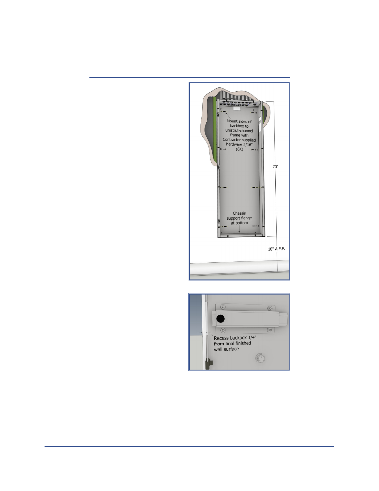
Isolated Power Systems should be located as close as possible to the point of use to
reduce leakage current associated with the branch conductors. Generally, panels
are installed inside the room being served, or just outside in an adjacent corridor
wall. An IPS is only permied to serve one operang room (with the excepon of
high voltage x‐ray/laser panels). When installed outside of the room, a remote an‐
nunciator is required inside of the room to nofy staffof an alarm from the LIM.
The Paent Care Vicinity is the primary focus for personnel fault protecon. This
area centers on the normal locaon of the surgical table/paent bed, extending 6
feet horizontally beyond the paent perimeter and vercally from the floor up to
the ceiling. Line powered, portable or ceiling mounted equipment which may ex‐
tend into this area such as service booms, pendants, monitors, C‐arms, and surgical
lights should be fed from an un‐grounded isolated power system for protecon
against line‐to‐ground faults without power interrupon. Fixtures and equipment
which do not extend down below the ceiling including overhead lighng should not
be connected to IPS. Non‐medical equipment such as personal computers, moni‐
tors, communicaon, and A/V equipment that is not intended to enter the paent
care vicinity should be fed from normal grounded power circuits with GFCI protec‐
on instead of IPS.
Note, as with most inducve loads, the inrush current of the IPS isolaon transform‐
er may be up to 15X its rated primary current and may take up to a second to sub‐
side, based on site condions. PGL highly recommends upstream feeder breakers
supplying any IPS panel include electronic or adjustable instantaneous trip capabili‐
es that are compable with the inducve load inrush current generated by the
isolaon transformer. Consult our website for a copy of PG LifeLink’s Isolated Power
System Design & Installaon Guidelines for more informaon.
Avoid connecng devices with commercial‐grade power supplies including low pass
filter networks or surge protecon circuits (TVSS or MOV line to ground) on IPS.
These devices include capacive coupled current paths from line to ground and can
raise the system Total Hazard Current. If in doubt, verify with device manufacturer if
equipment is compable with medical isolated power systems. In general, only
“Medical Grade” equipment should be connected.
Do not supply general lighng loads from IPS branch circuits. Permanently wired
overhead ceiling fixtures are considered outside of the Paent Care Vicinity and do
not pose a fault risk to the paent. Typical circuitry contained in these fixtures will
contribute a disproporonately high level of leakage current to the system, leading
to a reduced operang range. However, certain adjustable boom‐mounted lighng
devices such as surgical and exam lights as well as wall mounted x‐ray film view box‐
es are accessible to paents and staffand therefore do require IPS protecon.
Certain devices are not compable with IPS and therefore should not be installed on
IPS branch circuits. These include:
GFCI, AFCI, Surge Protected, and Isolated Ground type receptacles, as
well as some receptacles with integral USB charging capability

PG LIFELINK IPS PLUS Series Operaon and Maintenance Manual
© 2023 POST GLOVER LIFELINK, INC. ‐All rights reserved Page 9
Certain Medical‐Grade power strips with loss‐of‐neutral or loss‐of‐
ground sensing circuits
For addional informaon regarding system compability, contact PG LifeLink’s
engineering team at +1 800-287-4123 or techsupport@pglifelink.com
Upon compleng installaon, installer should perform the Contractor Isolated Power
System Start‐Up Procedure. A copy of this procedure is included with each panel and
may also be downloaded from our website at hp://www.pglifelink.com/technical‐
resources.
Back Box Installaon
Installaon of PG LifeLink Isolated
Power Panels is the responsibility
of the installaon contractor
including selecon and supply of
a suitable support structure and
aachment hardware. The size
and maximum weight for each
panel type is listed in Table 1.
PGL recommends securing panels
to a rigid support structure such
as channel‐strut using minimum
5/16” commercial grade hard‐
ware. Four mounng holes are
located on each side of the back
box for this purpose. If necessary,
use shims between the back box
and support anchorage to ensure
that the sides of the enclosure
are not distorted as the mounng
bolts are ghtened, which may
result in mis‐alignment of the
front trim mounng hardware.
NOTE: Do not locate any mounng hardware or conduit entry points on the rear sur‐
face of the back box. This will interfere with installaon of the interior equipment
chassis as well as the front trim panel.
When installing flush‐mount type panels, posion the boom edge of the back box
approximately 18 inches above the surface of the finished floor, and ensure that the
front edge is recessed approximately 1/8” behind the final finished wall surface. If
the backbox protrudes beyond the wall, or is recessed too far behind the surface,
this may cause difficulty when securing and aligning the front trim. Keep in mind
that final finished wall and floor dimensions may change significantly aer rough‐in
depending on the types and thicknesses of finishes applied.
For panels weighing 500 pounds or more, PG LifeLink recommends installing a lower
horizontal brace or saddle to support the underside of the backbox in addion to the
vercal side supports.
Model
Series
Total
Capacity
(kVA)
Enclosure
Size
(H x W x D)
Max.
Weight
(lbs.)
IPP‐P
3
70” x 24” x 6” 315
5
7.5
70” x 24” x 8” 385
10
IPX‐P
5/5
70” x 40” x 8”
600
7.5/7.5 635
10/10 690
IPL‐P
15
70” x 36” x 12”
565
25 685
IPD‐P
15 550
25 665
70” x 36” x 12”
Table 1: Weights and Dimensions

Page 10 © 2023 POST GLOVER LIFELINK, INC. ‐All rights reserved
PG LIFELINK IPS PLUS Series Operaon and Maintenance Manual
A label is affixed inside the back‐
box indicang the correct orienta‐
on. Be sure to install with the
top side facing up so that the
interior chassis will align properly
when installed. A raised chassis
support ledge is located along the
boom interior of the backbox.
Different models of backboxes
look similar. Verify that the part
numbers marked on the backbox
ID label matches the labels on the
associated equipment chassis and
front trim (shipped separately).
Install conduit prior to installing
equipment chassis assembly.
Remove all metal shavings and
clean interior to avoid contamina‐
on of equipment.
All conduit should enter from the
top of the enclosure to allow
proper clearance for installaon
of the equipment chassis assem‐
bly. Installer may locate and in‐
stall branch circuit conduits as
convenient along the top surface
of the back box, being careful to
maintain adequate separaon
between isolated branch circuit
conductors and non‐isolated feed‐
er conductors, as well as low‐
voltage signal wires connected to
the remote terminal block. Loca‐
on of primary main and remote
terminal connecon points vary
by model. Always refer to specific
project drawings when locang
conduit entry points.
If site condions require locang
conduit on the sides or boom of
the enclosure, it is recommended
that installer first pre‐install the
equipment chassis (and trans‐
former if shipped separate from
the chassis) prior to drilling to ensure proper clearance can be maintained.
Conduit runs for branch circuits should be as short and direct as possible to minimize
accumulated leakage current. Generally, the maximum recommended cumulave
Figure 1: Backbox Installaon
Figure 2: Backbox Recess

PG LIFELINK IPS PLUS Series Operaon and Maintenance Manual
© 2023 POST GLOVER LIFELINK, INC. ‐All rights reserved Page 11
length of for all branch circuit conductor pairs from a single transformer is 500 feet.
Avoid unnecessary bends and juncons where possible.
In accordance with NEC 517.13 (A), all branch circuit conduit shall be metallic and
“shall itself qualify as and equipment grounding conductor in accordance with [NEC]
250.118”. In Canada, branch circuit conduit must be non‐metallic in accordance with
CEC Part 1 Secon 24‐204(2)(f).
Interior Equipment Chassis Installaon
The equipment chassis has four
mounng slots which align with four
threaded studs on the inside rear of the
backbox. A mounng ledge is also pro‐
vided along the boom of the backbox
which supports the weight of the chas‐
sis and aligns it vercally with the front
trim.
When removing the chassis from its
packaging , transporng or liing it into
place inside the enclosure do not place
pressure on or use any of the compo‐
nents or brackets for liing. Use only
the sides of the main chassis plate for
liing. If the chassis assembly includes
an oponal power receptacle or ground
jack accessory plate it may be temporar‐
ily removed to facilitate chassis installa‐
on. Note that the equipment chassis is extremely heavy and can weigh up to several
hundred pounds. Do not aempt to lior install chassis assembly or transformer
without proper safety equipment. The two mounng slots at the top of the chassis
may be used as liing points.
To install the chassis, first rest its boom edge on the mounng ledge and align the
lower open ended slots with the studs in the rear of the backbox, then lt up and into
place, engaging the upper mounng slots with the studs. Secure with four 5/16‐18
nuts and washers provided, ensuring that chassis is flush against the rear of backbox.
A serialized idenficaon label is affixed to each equipment chassis as well as the
circuit breaker dead‐front barrier. Ensure that the serial numbers are the same on
both labels and do not switch barriers with another panel.
The Line Isolaon Monitor and wiring harness is included with the equipment chassis
and is packaged independently in cardboard to protect it during shipping and storage.
The LIM will be installed directly to the rear of the Front Trim in a subsequent step
(see Front Trim Secon). Do not remove the LIM from its packaging unl final assem‐
bly stage. Ensure that LIM is installed only with the equipment chassis with which it
was originally packaged. Note that connecng some older LIMs (such as the Mark V)
to a panel with the wrong voltage will cause severe damage to the device and will
void the warranty.
Figure 3: Chassis mounng ledge

Page 12 © 2023 POST GLOVER LIFELINK, INC. ‐All rights reserved
PG LIFELINK IPS PLUS Series Operaon and Maintenance Manual
Isolaon Transformer Installaon
While most chassis assemblies include a
pre‐wired, low‐profile isolaon trans‐
former mounted directly to the chassis
assembly, certain model types, including
IPD‐P and IPL‐P panels require installa‐
on of a separate, shelf‐mounted trans‐
former in the upper poron of the back‐
box. These components are typically
very heavy and require suitable liing
equipment. Use only the liing points
on either side of the top support rail
when liing or transporng transform‐
ers. Do not exert pressure on the wind‐
ings or wire leads while liing or manip‐
ulang.
To install upright, shelf‐mounted trans‐
formers, use appropriate liing equip‐
ment to remove from crate and carefully
suspend boom surface approximately
12” above the floor. Inspect lower rails
and mounng holes. Install the provid‐
ed rubber vibraon isolaon grommets
along with 5/16”‐18 bolts and fender
washers in each of the four mounng
holes (see Figure 4). Then carefully li
and posion the transformer above the
corresponding holes in the upper trans‐
former mounng shelf at the top of the
backbox. Carefully lower transformer
onto shelf, ensuring that all four bolts
slide freely into mounng holes. Secure
transformer mounng bolts to shelf with
provided 5/16” flat washers, lock washers,
and hex nuts from below. Tighten unl
rubber isolators compress approximately
1/8”.
Figure 5: Shelf‐Mounted Transformer
Figure 4: Equipment Chassis Installaon

PG LIFELINK IPS PLUS Series Operaon and Maintenance Manual
© 2023 POST GLOVER LIFELINK, INC. ‐All rights reserved Page 13
Wiring
Isolated Power Systems require a single‐phase, 3‐wire incoming power feed (H,H,G
or H,N,G). Verify that the incoming voltage matches the Primary Voltage listed on
the isolaon transformer as well as the project drawings. Both of the incoming
power conductors are connected directly to the line side terminals of the Primary
Main Circuit Breaker. This 2‐pole breaker is sized to protect the isolaon transform‐
er windings. Terminate the incoming grounding conductor on the ground bus.
The primary and secondary leads of the isolaon transformer are pre‐wired to the
main circuit breaker and panelboard lugs for IPP‐P and IPX‐P type panels. Installer
must terminate the transformer leads for IPD‐P, and IPL‐P type panels. Carefully
review the project shop drawings for each panel to verify the proper transformer
rangs (kVA, primary and secondary voltages), and compare to the data label on the
front of the transformer. Note the wire designators on the label and at the end of
each lead. Connect the primary winding (H1/H2) to the load side of the primary
main circuit breaker. Connect the secondary winding (X1/X2) directly to the panel‐
board lugs and connect the transformer grounding lug to the chassis ground bus
with the provided green insulated conductor. Reference Figure 6 for typical connec‐
ons. For IPD‐P panels with dual secondary winding transformers, the secondary
leads (X1/X2 & X3/X4) will connect to secondary main circuit breakers instead of
directly to the panelboard. Be certain to connect the correct set of leads to the
correct side of the panel based on the winding voltage. Note that mis‐wiring the
transformer leads can create an extremely hazardous situaon and may cause
catastrophic damage to the panel as well as any connected equipment.
Special low leakage wire should always be used for branch circuit wiring of isolated
power systems. Cross‐linked, polyethylene type insulaon with a dielectric constant
of less than 3.5, such as XHHW‐2 is highly recommended. Standard construcon
type wiring such as THHN may be used for the incoming primary feeds and equip‐
ment ground wires only. Refer to Informaonal Note No. 2 of NEC 517.160(A)(6).
For installaons in Canada, PG LifeLink recommends the use of RW 90 XPLE type
wire for all branch circuit conductors. Refer to CEC Part 1 ‐Secon 24‐204(2)(b).
As noted in the previous secon, the total length of branch circuit conductors fed
from each isolaon transformer should be kept as short as possible to minimize
accumulated leakage current of the system. The recommended maximum cumula‐
ve length for all branch circuits of each leg (L1 or L2) is 450‐500 feet per transform‐
er. Avoid unnecessary runs where possible, minimize the number of connecon
points, and limit addional “slack” conductor coiled up inside juncon and device
boxes.
All Isolated Power System branch circuits are protected by two‐pole circuit breakers
because there is no grounded neutral on the secondary output side of the trans‐
former. Up to a maximum of 16 branch circuit breakers may be installed on each
transformer. Refer to Figure 6.
The Naonal Electric Code (NFPA 70) requires isolated branch circuit conductor insu‐
laon to be colored orange and brown, with a disncve stripe running its length in
a contrasng color (other than white, green, or gray). Orange wires (L1) are con‐
nected to the upper pole of each branch breaker and to the silver terminal screw

Page 14 © 2023 POST GLOVER LIFELINK, INC. ‐All rights reserved
PG LIFELINK IPS PLUS Series Operaon and Maintenance Manual
(typical neutral side) of each NEMA receptacle in the circuit. Brown wires (L2) are
connected to the associated lower pole of each breaker and the brass terminal screw
(typical hot side) of each receptacle. Consistent polarity should be maintained
throughout the installaon. Reference NEC 517.160(A)(5) or CEC Part 1 24‐204(2)(c‐
d). See Figure 6 for a typical installaon wiring diagram.
Do not use pulling compounds to lubricate inside of conduit. This will break down
the insulaon properes and raise leakage current. A dry talc powder may be used.
It is recommended to use conduit with a slightly larger diameter to ease wire pulling
and avoid damage to the insulaon. An interior coang of PVC may also be used.
Reference NEC 517.160(A)(6).
Isolated power circuits must be kept separate from other circuits and may not share
conduit or raceway with non‐isolated circuits, or isolated circuits from another sys‐
tem. Reference NEC 517.160(A)(1).
The grounding terminals of each receptacle and hardwired device fed from the sys‐
tem must be connected to the Reference Ground Bus inside Isolaon Panel. When
mulple panels serve the same room or space, they must be bonded together locally
with a minimum #10 AWG insulated equipment bonding conductor. This includes
circuits from panels installed outside of the room, as well as non‐isolated (grounded)
circuits present in the room. Reference NEC 517.13 , 517.14, and 517.19.
Figure 6: Typical Isolated Circuit Wiring

PG LIFELINK IPS PLUS Series Operaon and Maintenance Manual
© 2023 POST GLOVER LIFELINK, INC. ‐All rights reserved Page 15
Where listed, follow component manufacturer’s specified ghtening torque for all
circuit breaker and bus lug electrical connecons. Where component manufacturer
specs are not available, torque all electrical connecons according to the values
listed in Table 2.
IPS Panels that include System Load Monitoring (SLM), Branch Circuit Load Monitor‐
ing (CLM), or Fault Locaon (FLS) opons have special requirements for roung
circuit conductors. The isolaon transformer H1 primary lead should be routed
through the System Load Monitor Current Transformer (CT). Refer to Figure 6.
Panels that include the Fault Locaon System (FLS) and/or branch Circuit Load Moni‐
toring (CLM) opons also require special branch conductor roung by the installa‐
on contractor. Each system includes one or two CT bank assemblies capable of
monitoring up to eight branch circuits each. If both opons are selected, up to four
CT banks will be installed (two on either side of the panelboard). The outermost CT
banks monitor CLM load current while the inner banks are used for FLS to idenfy
the circuit where a ground‐fault has occurred. Both isolated branch circuit conduc‐
tors (L1 & L2) should be routed through the associated FLS current transformer.
While, only the L1 conductor is routed through the CLM current transformer. See
Figure 6 for more details. The equipment chassis will also include labels with in‐
strucons for wiring these devices.
Panels with CLM and/or FLS include a set of DIN rail mounted fused dis‐connects.
These are located next to the CT Manager module above the main breaker.
The Line Isolaon Monitor connecon harness and remote terminal block (TB‐
REMOTE) are pre‐wired and installed on the equipment chassis. The LIM will be
mounted to the front trim panel during the final steps of installaon. Refer to the
specific user manual for the LIM being installed for detailed informaon on the
proper installaon, wiring, operaon, and maintenance of the LIM, including any
remote annunciators or accessories.
Wiring for low voltage remote annunciators and accessories should enter through
conduit at the top of the enclosure terminate on the appropriate poles of the Re‐
mote Terminal Block. Route and secure wires to maintain adequate separaon from
power conductors and terminals. Consult LIM User Manual for recommended type,
gauge, and length of remote wiring. When pulling and terminang remote wiring,
ensure that no conductors come in contact with the metal enclosure, conduit, or
earth ground. This can adversely affect operaon of the remote device as well as
the LIM.
Wiring Terminal Tightening Torque
Wire Size (AWG) 18‐10 8 6‐4 3‐1/0
Torque (lb‐in) 35 40 45 50
Table 2: Torque specs

Page 16 © 2023 POST GLOVER LIFELINK, INC. ‐All rights reserved
PG LIFELINK IPS PLUS Series Operaon and Maintenance Manual
Front Trim Installaon
A stainless steel front trim assembly is
included with each panel. The trim is
shipped with a protecve film covering
the brushed finish surface. Store flat, and
fully support trim panel when liing. Also
avoid leaning cover against wall or other
vercal surfaces to prevent bowing,
which can result in permanent warping or
mis‐alignment of the inset hinged breaker
access door. Verify that the front trim
matches the installed backbox.
Before installing front trim, locate trim
mounng hardware consisng of 1/4‐20
stainless steel truss head screws and
black clip‐on u‐nuts. Hardware is pack‐
aged with equipment chassis. Install u‐nuts
at each mounng hole locaon along the
perimeter of front flange of the backbox.
Once equipment chassis installaon and
wiring is complete and all finished wall
surfaces have been applied, the front trim
can be installed. The trim is mounted to
the backbox via three fully‐concealed
compound slide‐hinges. This feature
allows qualified users to easily open the
enclosure for maintenance/tesng with‐
out an exposed hinge or seam.
To install, first loosen thumb‐screws and
fully extend slides on each of the three
compound slide‐hinges along the leside
of the backbox. Slides are locked in re‐
tracted posion for shipment. Ensure
thumb‐screw on boom hinge drops into
lower cam posion to prevent the weight
of the trim plate pressing against finished
wall when open. See Figure 7.
Litrim panel and align drop pins with
pivot holes at the end of each hinge slide.
Lower trim to engage pins with slides.
See Figure 8. Note that trim panel cannot
be open more than 90°. Forcing panel to
open further will damage hinges and
likely cause mis‐alignment. If necessary,
remove door completed by liing it offof the hinges for full access. Lay trim flat when
not installed on hinges. Repeat steps above for reinstallaon.
Figure 8: Front Trim Installaon
Figure 7: Front Trim Installaon, lower
hinge detail

PG LIFELINK IPS PLUS Series Operaon and Maintenance Manual
© 2023 POST GLOVER LIFELINK, INC. ‐All rights reserved Page 17
Locate the Line Isolaon
Monitor that was
shipped with the panel’s
equipment chassis. LIM
is packaged in stac‐free
wrap and located inside
a small cardboard box.
Install LIM onto LIM
mounng bracket in
center of front trim plate
with four #4‐40 screws
provided. See Figure 9.
To connect LIM to chas‐
sis, with the harness
wires facing the rear of
the LIM carefully align
the plasc connector
with the 15‐pin header on the
boom of the case and fully insert. See Figure 10.
7 [177.8mm]
61
2[165.1mm]
4 [101.6mm]
43
8[111.3mm]
31
4[82.6mm]
61
8[155.3mm]
Figure 10: Line Isolaon Monitor Harness Connector
Figure 9: LIM Installaon

Page 18 © 2023 POST GLOVER LIFELINK, INC. ‐All rights reserved
PG LIFELINK IPS PLUS Series Operaon and Maintenance Manual
Refer to the User Manual for the LIM specific to the panel being installed for detailed
informaon on the proper installaon, wiring, operaon, and maintenance of the LIM,
including any remote annunciators or accessories.
To close front trim panel rotate halfway towards panel, then liup on the thumb screw
of the boom hinge to release it from the latched posion. While making sure all wires
and cables are clear, connue rotang to closed posion. Using even pressure, carefully
slide trim unl all edges are flush with finished wall surface.
Ensure there is adequate clearance between the front trim and internal equipment such
as transformer coils, dead‐front barrier flanges, and circuit breaker trip handles.
Secure the front trim to the backbox using the provided 1/4‐20x1” Philips truss head
stainless steel screws. Use a #3 Philips bit to avoid stripping screw heads. Do not over-
ghten.
To open panel, remove the 1/4‐20 screws and carefully pull the trim away from the wall
surface unl the boom slide‐hinge reaches the latched posion. Then rotate trim open
90°. to Carefully close front trim, ensuring that no wires are pinched, and install remain‐
ing screws.
Fill out panel schedule with circuit informaon and place in clear pocket behind breaker
access door.
6. Operation
Refer to Line Isolaon Monitor instrucon manual supplied with panel for complete
system operaon guidelines.
System Startup ‐Aer system has been properly installed and all wiring connecons
have been verified, energize the Primary Main Circuit Breaker in the Isolated Power
System panel. The LIM will undergo the following inializaon process each me unit is
energized:
1. Aer power is applied unit will perform a “lamp test”, illuminang all LED indica‐
tors and segments, as well as signaling audible alarm. The LCD screen displays cur‐
rent firmware version and serial number of the unit. If any problem is noted with
LEDs or displays, or if the audible alarm signal is not present, contact technical
support.
2. Aer “lamp test” is complete, the unit will enter self‐calibraon mode for approxi‐
mately 30 seconds. “Ca” is displayed on the LED screen, and the LCD display indi‐
cates “Status: Calibraon”.
3. Upon compleon of self‐calibraon, unit will enter normal operaon mode.
4. If this is the first me LIM has been energized, or if unit has been turned offfor
more than two weeks, a reminder to set the system me will appear. Refer to User
Menu secon of the LIM manual.
Normal Operaon ‐Under normal operang condions the LIM will exhibit the follow‐
ing:
1. The green “SAFE” indicator is illuminated, indicang unit is energized and condion

PG LIFELINK IPS PLUS Series Operaon and Maintenance Manual
© 2023 POST GLOVER LIFELINK, INC. ‐All rights reserved Page 19
is normal.
2. The red “HAZARD” and amber “SILENCED” indicators are exnguished. (Excepon:
if “Alarm Volume” has been set to “Mute” in the configuraon menu, the amber
“SILENCED” indicator will be connuously illuminated)
3. The 2‐digit mA display, along with the 16‐segment bar graph will indicate the calcu‐
lated Total Hazard Current for the Isolated Power System, including any connected
equipment.
4. The LCD display screen indicates “Status: System OK” along with the current me,
measured line‐voltage, and (if acvated) % of system full load.
THC Measurement ‐The primary funcon of the Mark V Line Isolaon Monitor is to
connuously monitor the line‐to‐ground impedance of both line conductors of a single
phase, ungrounded, Isolated Power System. A “fault” condion exists when a piece of
connected equipment causes this impedance to drop significantly, causing a proporon‐
al rise in the calculated Total Hazard Current (THC). When the THC exceeds the selected
alarm threshold value of 5 mA or 2 mA, audible and visual alarms are triggered on the
front of the LIM as well as on any connected remote annunciators.
System Load Monitoring ‐When installed and configured, the oponal System Load
Monitor (SLM) feature connuously displays the total system load current as a percent‐
age of the main breaker trip rang on the LIM’s user interface. Users can set a pre‐
alarm threshold value (default 80%) to nofy when system load is nearing breaker trip
point to avoid potenal overload and shutdown of panel. Refer to LIM manual for more
detailed informaon.
Circuit Load Monitoring ‐When installed and configured, the oponal Circuit Load Mon‐
itoring (CLM) feature connuously monitors the load current to each individual branch
circuit. A pre‐alarm value (default 80%) can be set for each circuit to nofy staffof po‐
tenal overload and loss of parcular branch circuit(s). When pre‐alarm is triggered,
relevant informaon is displayed on the LIM’s status screen. Status can also be ob‐
served via LEDs on the FLCLMS CT Manager module located behind the breaker access
door. Refer to LIM manual for more detailed informaon.
Fault Locaon System ‐When installed and configured, the oponal Fault Locaon Sys‐
tem (FLS) feature is automacally acvated whenever the measured THC of the IPS rises
above 4.8 mA, indicang the potenal of a line‐to‐ground fault on the system. The FLS
analyses each branch circuit and determines which one is contribung the highest incre‐
mental THC. The circuit number is idenfied on the LIM’s status display and also via
LEDs on the FLCLMS CT Manager. Refer to LIM manual for more detailed informaon.
7. Troubleshooting
Refer to Line Isolaon Monitor instrucon manual supplied with panel for ps on trou‐
bleshoong common problems. For addional technical support, contact PG LifeLink at
+1 800-287-4123, or via email at techsupport@pglifelink.com.

Page 20 © 2023 POST GLOVER LIFELINK, INC. ‐All rights reserved
PG LIFELINK IPS PLUS Series Operaon and Maintenance Manual
8. Maintenance
PG LifeLink recommends annual tesng of all Isolated Power Systems and Line Isola‐
on Monitors in accordance with the requirements located in NFPA 99 ‐Health Care
Facilies Code. Recommended tesng includes:
Measurement of secondary output voltage(s)
Measurement of system Total Hazard Current (THC)
Verificaon of Line Isolaon Monitor alarm points using simulated fault imped‐
ance
Verificaon of all other Line Isolaon Monitor and Remote Annunciator alarm
signals
Verificaon of ground system integrity
Panels are covered by a standard two (2) year manufacturer’s warranty from date of
purchase. If the unit is determined to be non‐conforming, contact PG LifeLink immedi‐
ately at +1 800-287-4123, or via email at techsupport@pglifelink.com. A technical
support associate will assist in trouble‐shoong the issue, and if necessary, arrange
for return of the item via our standard RMA process. PG LifeLink will analyze the
equipment to verify non‐conformance and determine the root cause. At its opon,
PG LifeLink will either repair or replace returned equipment during this period, provid‐
ed that no abuse or damage to the product has occurred, and unit has been properly
installed and operated in accordance with this manual. PG LifeLink reserves the right
to modify this policy.
Replacement circuit breakers and Line Isolaon Monitors are available. Contact sales
at +1 800-287-4123 for current pricing and availability. Have the Sales Order (SO) and
panel serial numbers available to assist in verifying compability.
The IPS does not contain any user‐serviceable parts. Tampering by personnel without
prior wrien authorizaon from the factory voids the warranty, and may also void
applicable agency cerficaons.
This manual suits for next models
4
Table of contents
Popular Power Supply manuals by other brands

Crestron
Crestron CNPWS-75 Operation guide

Pyle
Pyle PSL122X instruction manual

Thermaltake
Thermaltake Toughpower Grand user manual

BE QUIET!
BE QUIET! SFX POWER 3 user manual

Agilent Technologies
Agilent Technologies 664XA Series Programming guide

McLED
McLED ML-910.007.22.0 Instruction and Illustrated manual