Advanced Energy Industries RF Power Products RF Series User manual

U
S
ER
MANUAL
Fort Collins,CO 80525 USA
970.221.4670
1625 Sharp Point Drive
Advanced Energy Industries,Inc.
4(
4GXKUKQP
#
1EVQDGT
@RFPP
RF
Pow•
r
Product
a
Inc.
RF
POWER
SUPPLY
OPERATOR'S
MANUAL
RF
SERIES 10/2S
REVISION
6.00
DOCUMENT
NUMBER
21-22303-901
CC>
COPYRIGHT 1996 RFPP, INC.
1007 LAUREL OAK ROAD VOORHEES,
NEW
JERSEY 08043
ALL RJGHTS RESERVED 1996

IIREV
0
A
B
DOCUMENT:
RF
Power
Suppl.y
Operator's
Manual.
RF
SERIES
10/25,
REVISION
6.00
DOCUMENT
No.:
21-22303-901
ENGINEERING
APPROVAL:
CUSTOMER
SERVICE
APPROVAL:
Mike
Kelly
Rene
Clement
Monica
DeMarco
QA
APPROVAL:
DATE
APPROVAL
REVISION DESCRIPTION
9/27/97
Mike
Kelly
Released
per
EPR
430.
7/22/97
Mike
Kelly
Analog
pulse
mode
section
lt/;3j9
"?
<7&f-
changed
per
ECN
3468.
Word
correction,
pg
12
per
ECN
3670.
iii
II
TABLE
OF
CONTENTS
.,
SECTION l
GENERAL
INFORMATION.................................................................................................................-
1.l INTR.ODUCTION
.••
-...............................................................................................................................2
1.2
PURPOSE
................................................................................................................................................2
1.3
RA
TED
POWER.
..........................................................................................····..·...•....········........·········..·2
1.4
GENERAL
DESCRIP1lON
··-······································-·······································································::?
1.5
TiiEFRONTPANEL
..............................................................................................................................3
1.5.l
POWER.
.............................................•...•.....................•..........................................................3
1.5.2
RF
ON/OFF
BUTION
...........................................................................................................3
1.5.3
MULTIFUNCTION
BUTIONS
............••..................•..•........•................................................3
1.6
REAR
PANEL
CONTROLS
AND
CONNECTIONS.............................................................................3
1.6.1
CIRCUIT
BR.EAKER•••....•••..••..••...•..............•••.......••••.....................•.....................................3
1.6.2
AC
INPUT..............................................................................................................................3
1.6.3
CEX
IN ..........................................................................-•••....•...•..••........•......•.......................3
1.6.4
CEX
OUT
••..••.....•••..•.••••••...••.••••••...••...••••....•....•........••.••.................•......................................3
1.6.5 POWER/VOLTAGE*
AND
RF/DC•
INPUTS
......................................................................4
1.6
.6
PRESET
INVOKE•
................................................................................................................4
1.6.7
PPO,
PPl,
AND
PP2................................................................................................................4
1.6.8
EXTINLK
............•.....•............................................................................................................4
1.6.9
GA
TE......................................................................................................................................4
1.6.10
RAMP
ENABLE•
.................................................................................................................5
1.6.11
RFON•
...•..............................................•....•..•..••........•.......•...........•..............•.......•.......•.......5
1.6.12
RFENABLED•
....................................•........•...........•..•..•.....•.......................•.......................5
1.6.13
GATE
ENABLE•
.................................................................................................................5
1.6.14
+15V
......•....................•........................•.....•.......................................................................•..5
1.6.15
-15V
...............................................................................•.............•........................................5
1.6.16 +SV .......................................................................................................................................5
1.6.17
INCMON/MPl
......................................................................................................................7
1.6.l8 REFMON/MP2.....................................................................................................................7
1.6.19
RF
PROBE
...........................................•..............•......•...••....................•.•........••..••.........••..•..7
1.6.20
DC
PROBE...........................................................................................................................7
1.6.21 AUX PROBE...................................................................•....................................................7
1.6.22
FBL
-
FEEDBACK
LOW
....................................•...................................•........•...................
7.
1.6.23
SETPOINT
#1.......................................................................................................................7
1.6.24
SETPOINT
#2.......................................................................................................................8
1.6.25
GROUND
SENSE
................................................................................................................8
1.6.26
REMOTE
LIMIT
IN ........................................................•....................................................8
1.6.27
REMOTE
LIMIT
OUT
SHIELD
CONNECTION .......................................•.......................8
1.6.28
SHIELD
CONNECTION.................................................•.......................••..........................•8
1.7
TECHNICAL
SPECIFICATJONS..................................................................................•.....•...............•
11
1.8 STANDARD ACCESSORIES...............................................................................................................14
1.8.1
ACLINECORD
.•....................•..........••.........................•••.•............................................•.....
14
1.8.2
PROGRAMMING
PLUG
.....................................................................................................14
l·:9
·F
kCTORY
REP
AIR..............................................................................................................................
14
iv
TABLE
OF
CONTENTS
SECTION Il INSTALLATION AND OPERATION......••..•..•....•.•.........•...•.......•..•.................•................................
15
2.1 GENERAL.......................................................................................-••
.•••••••••••••••.•••..•••....•..••................
15
2.2 UNPACKING ........................................................................................................................................
15
2.3 INSTALLATION.................................................._.............................................:·································
16
2.3.1 GROUNDING ......................................................................................................................
16
2.3.l
LINE
TAPS...........................................................................................................................
16
2.3
.3
WATER COOLED SUPPLIES ..........................................................................................
..
16
2.3.4 TiiERMALCONSIDERATIONS......................................................................................
..
17
2.3
.S
CHECKOUT.........................................................................................................................
19
2.4 OPERATIONAL DESCRIPTION .........................................................................................................
21
2.4.I PANEL MODE.....................................................................................................................
21
2.4.2 ANALOG MODE.................................................................................................................
23
2.4.3 ANALOG PULSE MODE....................................................................................................26
2.4.4 SERIAL CONl'R.OL..................................................._ .......................................................28
2.4.4.1 232 INTERFACE OPTION.................................................................................28
2.4.4.2 422 INTERFACE OPTION.................................................................................28
2.4.4.3 RFPP MULT-DROP PROTOCOL......................................................................29
2.4.4.4 485-WIRE
AND
485-WIRE OPTIONS•..•••••.••...•..........................•.•.............•....
31
2.4.4.5 422, 485-2 AND 485-4 BUS TERMINATIONS ...............................................3I
2.5 MULTl-GENERATOR OPERATION....................................................................................36
2.5.l CALIBRATION PROCEDURE FOR DUAL GENERATOR SYSTEM .•..•..•..••..36
2.5.2 CALIBRATION PROCEDURE FOR QUAD GENERA
TOR
SYSTEM...•......•.•.37
SECTION III FRON"r PANEL PROGRAMMING ...................................................................................................
41
3
.1
STATUS ENVIRONMENT AND ADJUSTMENT BUTTONS...........................................................
41
3.2 PROGRAMMING ENVIRONMENT AND PROGRAM BUTTON ....................................................
41
3.3 MOVEMENT WITHIN THE PROGRAMMING ENVIRONMENT ...................................................42
3.4 FRONT PANEL PARAMETER PROGRAMMING.............................................................................42
3.5 STATUS ENVIRONMENT MNEMONICS .........................................................................................44
3.5.l CONTROL............................................................................................................................44
3.S.2 OPERATIONAL MODE......................................................•.............•...••......................••.•..44
3.5.3 EXT CEX..............................................................................................................................44
3.5.4 PULSING/RAMPING/PROGRAMMABLE PRESETS ......................................................45
3.6 ALARM AND LIMIT CONDITION MNEMONICS............................................................................45
3.6.l RF OFF ALARM AND LIMIT MNEMONICS ...................................................................45
3.6.1.l COVER INTERLOCK ALARM (4 SPACES)..................................................
..
45
3.6.l.2 EXTERNAL INTERLOCK ALARM (4 SPACES) ............................................45
3.6.l.3 PA UNBALANCE/FAN/TEMP ALARM (4 SPACES)......................................45
3.6.l.4 HIGH
OR
LOW LINE VOLTAGE ALARM (12 SPACES)...............................46
3.6.2 RF ON ALARM AND LIMIT MNEMONICS.....................................................................
46
3.6.2.l MAX POWER LIMIT
(5
SPACES)....................................................................
46
3.6.2.2 REF LIMIT (6 SPACES)....................................................................................46
3.6.2.3 PA CURRENT LIMIT (4 SPACES) •...•..•...... ....................................................46
3.6.2.4 POWER DISSIPATION/RF OUTPUT ALARM (5 SPACES)...........................
46
V

TABLE
OF
coNTENTS
3.7
PROG~G
ENVIR.ONMENT COLU}dNS ...............................................................................
47
3.
7
.1
ANALOG COLUMN -.........-............................................................................................47
3.
7.2 PRESETS COLUMN............-.............................................................................................
49
3.
7.3 PULSING COLUMN............................................................................................................
51
3.7.3.l
A WORD
ON
PROGRAMMINGSTARTPULSEPARAMETERS
.................
53
3.7.4 OPERATE COLUMN ..........................................................................................................56
3.7.5 SYSTEM COLUMN.............................................................................................................59
SECTION IV PRESETS............................................................................................................................................
61
4.1 INTRODUCTION
.•
-.............................................................................................................................6 l
4
.2
PRESET PARAMETERS......................................................................................................................
61
4
.3
PRESETOPERATION..........................................................................................................................63
4.3.l
INDIVIDUAL PRESETS
·--
..-......................................................................................
63
4.3.2 SEQUENTIAL PRESETS....................................................................................................
63
4.3.3 PRESETS
AND
MULTI-GENERATOR SYSTEMS...........................................................64
4.4 PROGRAMMING PRESETS................................................................................................................65
4.4.1
PANEL
PROGRAMMING
OF
PRESE'TS ..........................................................................65
4.4.2 SERIAL
PROGRAMMING
OF
PRESE'TS.••.•••........•...•.••••....•.•..........................................
67
4.5 EXECUTING PRESETS........................................................................................................................67
4.5.I PANEL..................................................................................................................................67
4.5.2 ANALOG.••.•..•••.•...••••....•.•...•....••••........•......•.............•.......•.............................•......•...•....•....67
4.5.3 SERIAL.................................................................................................................................70
4.6 PRESET CLOCK...................................................................................................................................
71
ADDENDUMS
SECTION V SERIAL PROGRAMMING ........................................................................................ CONSULT RFPP
SECTION VI FRONT
PANEL
SERVICING OF
11IE
GENERATOR........•..•................................ CONSULT RFPP
vi
TABLE 1
TABLE2
TABLE3
LIST
OF
TABLES
ANALOG INTERFACE PIN
LIST
..................................................................................................9
TECflNICAL SPECIFICATIONS..................................................................................................
11
RF SERIES 10/25 PROGRAMMING ENVIRONMENT COLUMNS..........................................43
LIST
OF
FIGURES
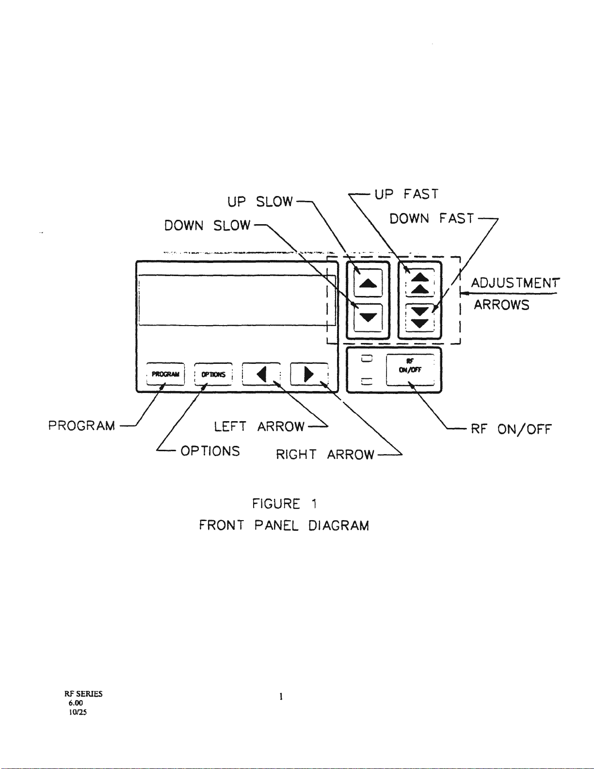
FRONT PANEL DIAGRAM ........................................................................................................................................ 1
ANALOG INTERFACE CONNECTOR................•.....................................................................................................6
WATER FITTINGS ILLUSTRATION.......................................................................................................................
18
CI-IECKOUT CONFIGURATION..............................................................................................................................
20
PANEL OPERATION.................................................................................................................................................22
FULL ANALOG DCV OPERATION CONFIGURATION.......•...............................•....•..........................................24
FULL ANALOG DCV OPERATION WITH MATCHING NETWORK PRESETS.................................................25
ANALOG PULSE MODE .........•...•............................................................................................................................27
DB25/DB9 PINOUTS .................................................................................................................................................30
SERIAL CABLES
232
AND
485 2-WIRE CONTROLLER CONNECTIONS..........................................................•...............32
485 4-WIRE
OR
422 CONNECTIONS...................................................................................•....................33
MULTI-DROP BUS LAYOUT....................................................................................................................34
SINGLE DROP BUS LAYOUT...................................................................................................................35
DUAL GENERATOR CONFIGURATION •...................................•...•.....•......•.....•...................................................38
QUAD GENERATOR CONFIGURATION...............................................................................................................
39
LIMIT POT ADJUSTMENTLOCATION ...................................................................................................•.............
40
PROCESS PULSE/ START PULSE TIMING............................................................................................................54
PRESET TIMING .......................................................................................................................................................62
DUAL GENERATOR PRESET CONNECTION...•...................................................................................................68
FULL ANALOG DCV WITH PRESET CONNECTIONS ........................................................................................69
APPENDIX A..............................................................................................................................................................72
vii
PROGRAM
RF
SERIES
6.00
10/25
DOWN
DOWN FAST
I•
ADJUSTMENI
I ARROWS
I
LEFT
RIGHT
AR~
RF
ON/OFF
FIGURE 1
FRONT PANEL DIAGRAM
SECTIONI
GENERAL
INFORMATION
1.1
INTRODUCTION
This volume provides the operating instructions for the RF
and
HF series generators (also referred to as the
generator, the unit, the equipment, the RF supply
or
the supply), manufactured by RFPP Inc., Voorhees, New
Jersey. This volume discusses thepurpose, application and technical characteristics
of
the generator.
WARNING:
1.2
PURPOSE
This power supply operates using lethal voltages and is capable
of
producing hazardous RF
voltages.
DEA
m
ON
CONT
ACT
may result from failure to observe
SAFETY
precautions.
When working inside the equipment, make certain the RF
power
supply is disabled at the wall
disconnect.
In tpe unlikely event that operation
of
the RF power supply is required with access covers
removed, do not allow body contact with any electrical component, tap, terminal
or
connection.
Use only heavily insulated tools and test equipment to make measurements and adjustments.
The generator is a unique microprocessor based RF power supply designed to provide the user with a
flexible set
of
options for control. The supply provides the user with a pure, stable power source from Oto the
generator's rated power.
1.3
RATED
POWER
RF5
HF5
RFIO
HFI0
500 Watts
500 Watts
1000 Watts
1000 Watts
1.4
GENERAL
DESCRIPTION
RF20
RF20H
RF30
2000 Watts
2000 Watts
3000 Watts
With
RF
ON, forward and reflected power are shown on the top line
of
the Vacuum Fluorescent Display
(VFD). With RF OFF, setpoint and max power are shown on the top line
of
the VFD. Additional generator.status.
information is typically displayed on the bottom line
of
the VFD. Blinking mnemonics on the bottom line
of
the
VFD convey limit
or
alarm conditions as well as the quality
of
the match.
The generator is a simple stand alone RF power supply in the PANEL mode. PANEL mode
is
front panel
operation. Power level is set via the four adjustment arrow buttons on the front panel. Feedback for the high speed
regulating circuits is supplied by the internal directional coupler (power control) or, for CPU controlled regulation,
the selected feedback terminal (voltage control). For more on panel programming, see Section III in this manual.
The ANALOG control mode allows control
of
the generator via external analog
and
digital control signals.
The-SERIAL control mode is the most
·t1eX:ible
mode
of
control. The unit can
be
configured to operate in
this mode with a minimum number
of
external connections to the system controller. Under SERIAL control the
supply may be configured, power level set and status monitored over a simple serial link.
RF
SERIES
6.00
10/25
2
1.5
THE
FRONT PANEL
1.5.1 POWER
This is the
AC
powerswitch for the generator.
1.5.l
RF
ON/OFF BUTTON
When
RF
is ON, this button is
alwlYJ
active
and
turns RF OFF
if
momentarily depressed.
When
RF
is OFF and front panel
RF
ON is permitted, this button turns
RF
ON
if
momentarily depressed.
1.5.3 MULTIFUNCTION BU'ITONS
. There are 8 additional tactile buttons called
ADJUSTMENT
ARROWS on the front panel
of
the generator.
These multifunction buttons
(4
below the
VFD
and 4 to
the
right
of
the VFD) arc explained in detail
in
Section
III
(PANEL PROGRAMMING)
of
this manual.
1.6
REAR PANEL CONTROLS
AND
CONNECTIONS
1.6.1
CIRCUIT
BREAKER
The circuit breaker provides ovcrcurrent protection for the power supply. It
DOES
NOT provide short
circuit protection. An additional breaker with high current interrupt capacity
or
a set
of
fuses should be included in
the system for safety. This breaker is
the
AC main disconnect for the generator.
To
operate the supply, place the
lever
in
the up position.
1.6.2
AC
INPUT
Attach included line cord to unit.
1.6.3 CEX
IN
Common exciter input for applications requiring synchronous operation
of
RF generators. The source can
be
another RF supply
or
CEX
product. Input impedance
is
SO
Ohms and the required level is 7-20 volts P-P at the
operating frequency.
1.6.4
CEXOUT
Common exciter output for applications requiring synchronous operation
of
RF generators. The signal is
compatible with
CEX
input
of
RF supplies. Output impedance is 50
Ohms
and the level is 8 volts P-P at the
operating frequency.
RF
SERIES
6.00
10/25
3
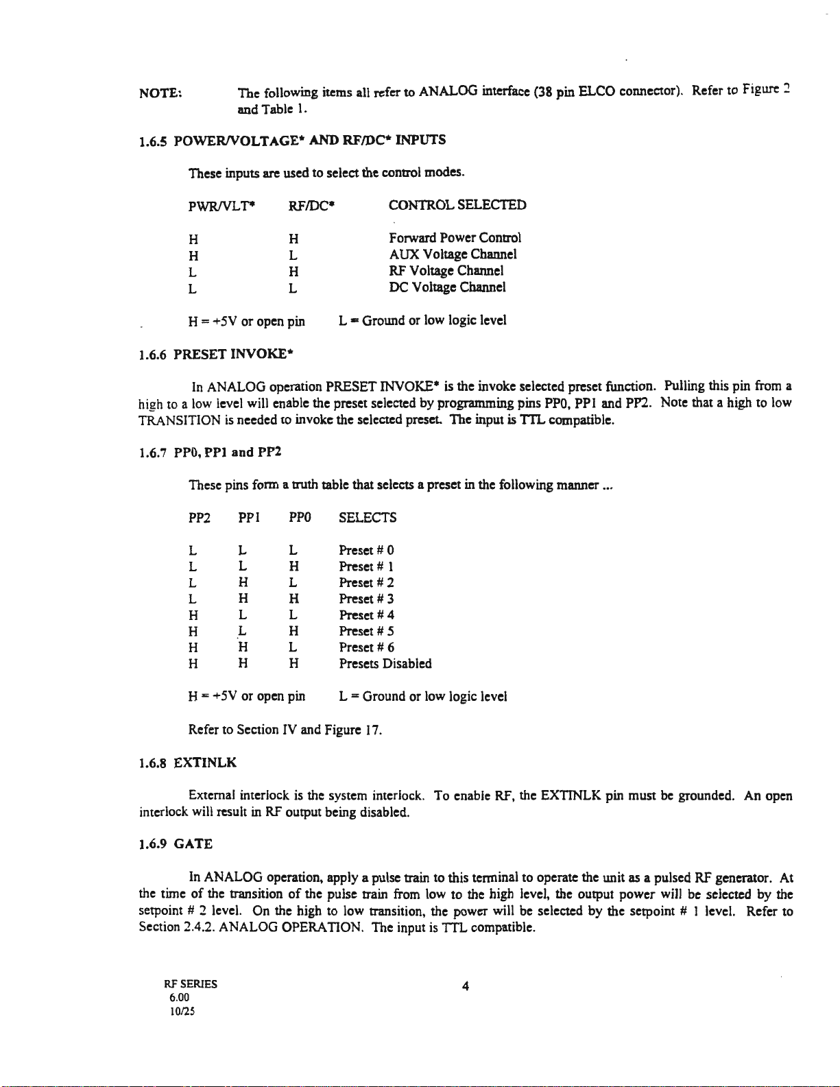
NOTE:
The
following items all refer
to
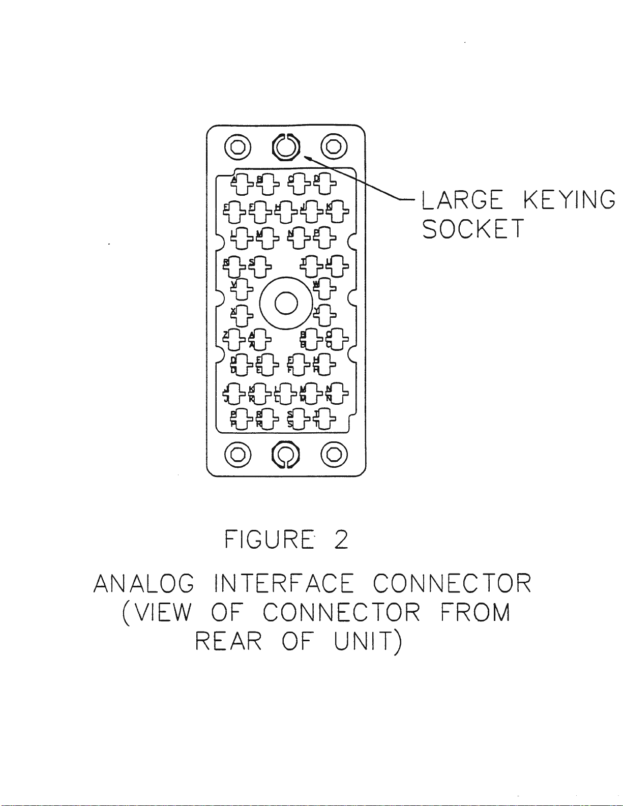
ANALOG interface (38 pin ELCO connector). Refer to Figure 2
and Table
l.
1.6.5
POWERNOLTAGE*
AND RF/DC* INPUTS
These inputs arc used to selectthe control modes.
PWRNLT*
H
H
L
L
H
L
H
L
H =+5V
or
open pin
I.6.6
PRESET
INVOKE*
CONTROL
SELECTED
Forward
Power Control
AUX Voltage Channel
RF
Voltage Channel
DC Voltage Channel
L • Ground
or
low logic level
In ANALOG operation PRESET INVOKE• is the invoke selected preset function. Pulling this pin from a
high to a low level will enable the preset selected by programming pins PP0,
PPl
and PP2. Note that a high to low
TRANSITION
is
needed to invoke the selected preset.
The
input is TTLcompatible.
1.6.7 PP0,
PPI
and
PP2
These pins form a truth table that selects a preset in the following manner ...
PP2
PPI
PPO
SELECTS
L L L
Preset#
0
L L H
Preset#
I
L H L
Preset#
2
L H H
Preset#
3
H L L
Preset#
4
H L H
Preset#
5
H H L
Preset#
6
H H H Presets Disabled
H =+5V
or
open pin L =Ground or low logic level
Refer to Section IV and Figure I7.
1.6.8 EXTINLK
External interlock
is
the system interlock. To enable RF, the EXTINLK pin must be grounded. An open
interlock will result in RF output being disabled.
1.6.9 GATE
In ANALOG operation, apply a pulse train to this terminal to operate the unit as a pulsed RF generator. At
the time
of
the transition
of
the pulse train from low to the high level, the output power will be selected by the
setpoint # 2 level. On the high to low transition, the power will be selected by the setpoint # I level. Refer to
Section 2.4.2. ANALOG OPERATION. The input is TTL compatible.
RF
SERIES
6.00
10/25
4

1.6.10
RAMP
ENABLE*
In ANALOG operation RAMP ENABLE is the
RAMP
AT
RF
ON
function. Pulling this pin from a high
to
a low level enables
ramping.
The
input
is
TIL
compatible.
1.6.11 RFON*
In ANALOG operation RFON* is the
RF
ON/OFF function. Pulling this pin from a high to a low level
enables RF. Note that a high
to
low transition is REQUIRED
to
tum
RF ON. The input is 1'TL compatible.
1.6.1:Z
RFENABLED*
RFENABLED*
is
a status line indicating that
RF
is
ON,
or
RF
is
ON
and OK. Alternatively, in the preset
mode the logic
is
reversed and it becomes the PRESET ENABLE signal for the PS2A Matching Network
..
Controller. Refer
to
Section 2.4.2.
NOTE:
This
is
an
open collector output.
1.6.13
GATE
ENABLE*
Pulling this pin low enables the ANALOG pulse mode. The input
is
1TLcompatible.
1.6.14
+lSV
+15V is a positive 15 volt
DC
source whose designed purpose is
to
generate a positive external setpoint
using an external
IOk
potentiometer in ANALOG operation. The unit must be programmed for positive polarity.
See POLARITY PROGRAMMING.
+15V
has a 470 Ohm output resistance with a maximum allowable current
draw
of
15
mA.
1.6.15 -15V
-1
SV is a negative
15
volt
DC
source whose designed purpose is to generate a negative external setpoint
using an external 1
Ok
potentiometer in ANALOG operation. The unit
must
be programmed for negative polarity.
See POLARITY PROGRAMMING. -15V has a
470
Ohm output resistance with a maximum allowable current
draw
of
15
mA.
t.6.16
+sv
+5V has a maximum allowable current
draw
of25
mA.
NOTE:
RFPP does not recommend using the +15, -15 and +5 output voltages in new designs.
RF
SERIES
5
6.00
10/25
@©@
0000
00000
0000
:6~8
o0o
00 00
0000
00000
0000
@@@
FIGURE·
2
LARGE
KEYING
SOCKET
ANALOG
INTERFACE CONNECTOR
(VIEW
OF
CONNECTOR
FROM
REAR
OF
UNIT)
1.6.17
INCMON/MPI
INCMON
is
an
analog output
that
has two functions. In the
nonnal
mode
of
operation there
is
a voltage
present
on
this terminal
that
is linearly related
to
the forward
power.
Toe
voltage is +SV at
rated
power. Accuracy
is±
.5
% full
scale±
3%
reading; resolution is 1 Watt.
When
the
Load &
Tune
function is enabled.
the
tcnninal is a forward
power
monitor
(above), while
RF
is
ON,
and
a preset voltage
for
the
nine
capacitor in
the
AM-SERIES
matching network
when
RF
is OFF. Refer
to
Figure 7 and Section 2.4.2.
1.6.18 REFMON/MPl
REFMON
is
an
analog output
that
has
two
functions. In the
normal
mode
of
operation there is a voltage
_,present on this terminal
that
is
linearly related
to
the reflected
power.
The
voltage
is
+5V
at
10%
of
rated power.
Accuracy
is
±
.5
o/o
full
scale
:I:
3% reading; resolution
is
I Watt.
When the
Load
&
Tune
function
is
enabled.
the
terminal is a reflected power
monitor
(above), while
RF
is
ON. and a preset voltage for the load capacitor in the AM-SERIES matching network
when
RF
is OFF. Refer
to
Figure 7 and Section 2.4.2.
1.6.19 RFPROBE
The feedback necessary for
RF
voltage control
is
applied
to
this terminal.
The
input
is
differential with an
impedance
of
47k
Ohms. Sec Section 2.4.2
and
Figures 6 & 7.
1.6.20
DC
PROBE
The feedback necessary for
DC
bias voltage control is applied
to
this terminal.
The
input is differential
with an impedance
of
47k
Ohms. Sec Section 2.4.2
and
Figures 6 & 7.
1.6.21 AUX PROBE
The
feedback necessary for
AUX
voltage control is applied
to
this terminal.
The
input is differential with
an impedance
of
47k
Ohms. See Section 2.4.2
and
Figures 6 &
7.
1.6.22
FBL
-FEEDBACK LOW
The voltage control feedback channels can be factory configured as single-ended
or
differential.
The
aforementioned probe input terminals
arc
all the HIGH inputs
of
a differential pair.
The
FBL
tenninal is the
LOW
side
of
all probe inputs when
they
are configured as differential inputs.
1.6.23
SETPOINT
# I
SETPOINT
# 1
is
the
standard
power
and voltage setpoint
input
ln
the
power
mode,
the
setpoint
is
linear
over
a
±5
or
±10
volt
range
from
Oto
rated power.
See
RANGE
and
POLARITY
PROGRAMMING.
Input
impedance is
47k
Ohms.
In
the
voltage control
mode,
the
control loop
will
alter the
power
until the setpoint
and
feedback signals
arc
equal.
The
voltage-setpoint/power transfer function
is
a function
of
the
probe
attenuation and
load impedance.
NOTE:
SETPOINT
# I
is
also used as the high
power
level in
ANALOG
pulse operation.
RF
SERIES 7
6.00
10/2S

1.6.24
SETPOINT
# l
SETPOINT # 2
is
the secondary
setp<>int
input. In ANALOG pulsed operation, the setpOint
is
linear over a
:1:5
or
:!:IO
volt range from Oto rated power. See RANGE AND
POLARIIT
PROGRAMMING. Input impedance
is47k
Ohms.
NOTE: This input is used as the low power level in ANALOG pulse operation.
1.6.25 GROUND SENSE
The GROUND SENSE line is the reference input for setpoint inputs and monitor outputs.
1.6.26
REMOTE
LIMIT
IN
The REMOTE LIMIT IN signal
is
designed to fold the generator back under external limit conditions.
Typically this input
is
used in dual bias systems. Input impedance
is
I
Ok
Ohms. See Section 2.5.
1.6.27
REMOTE
LIMIT
OUT
REMOTE LIMIT OUT
is
an analog signal which represents the level
of
reflected voltage sensed by the
supply. The signal
is
not
linearly related to reflected power. Typically it
is
used in dual bias systems. See Section
2.5.
1.6.28 SHIELD
CONNECTION
SHIELD MilSI
be
tenninated
at
one end
of
the analog cable. Empirical testing may
be
required· to
determine the best termination point.
Rf
SERIES
6.00
10/25
8
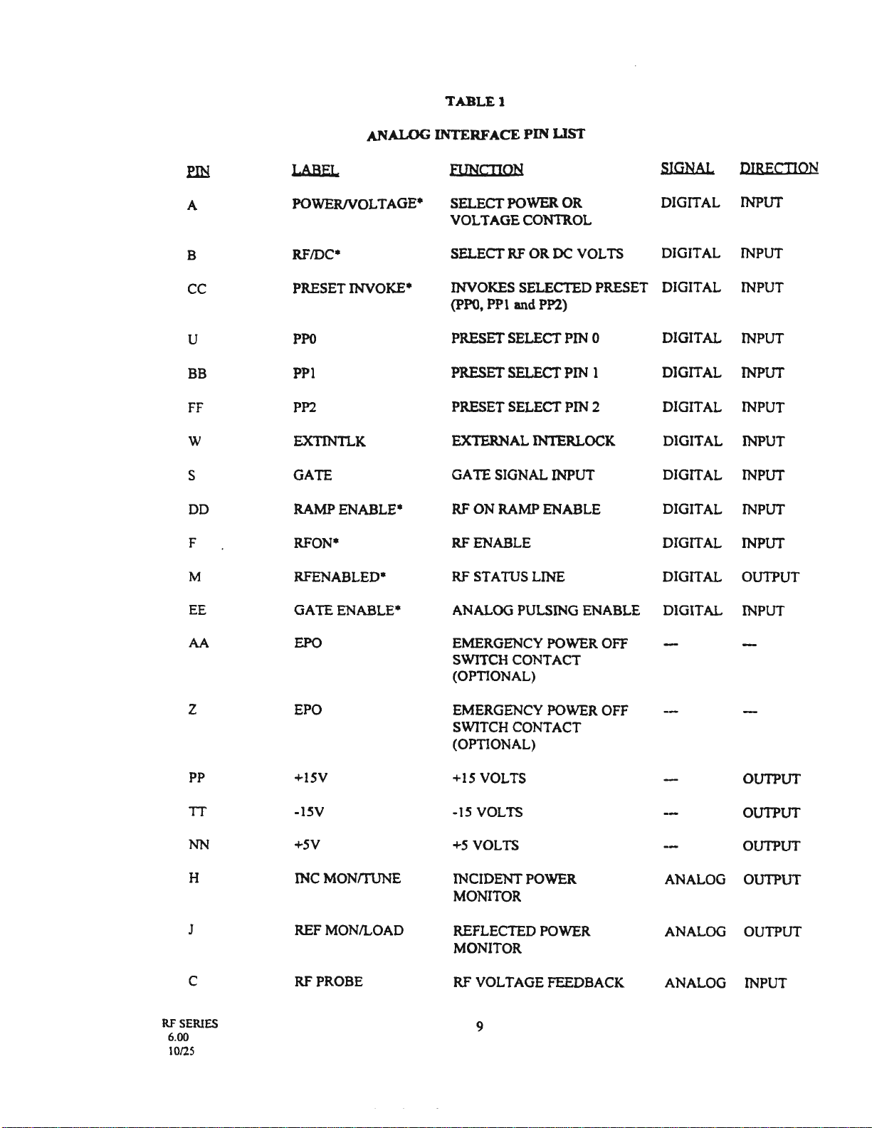
TABLEl
ANALOG
INTERFACE
PIN
LIST
flli
LABEL
FUNCTION
SIGNAL
DIRECTION
A POWER/VOLTAGE* SELECT POWER OR DIGITAL INPUT
VOLTAGE CONTROL
B RF/DC* SELECT
RF
OR
DC
VOLTS DIGITAL INPUT
cc PRESET INVOKE* INVOKES SELECTED PRESET DIGITAL INPUT
(PPO,
PPl and PP2)
u
PPO
PRESET SELECTPIN 0 DIGITAL INPUT
BB
PPl PRESET SELECTPIN 1 DIGITAL INPUT
FF
PP2 PRESET SELECT PIN 2 DIGITAL INPUT
w EXTINTLK EXTERNAL INTERLOCK DIGITAL INPUT
s GATE GATE SIGNAL INPUT DIGITAL INPUT
DD
RAMP ENABLE*
RF
ON RAMP ENABLE DIGITAL INPUT
F RFON* RF ENABLE DIGITAL INPUT
M RFENABLED*
RF
STATUS LINE DIGITAL OUTPUT
EE
GATE ENABLE* ANALOG PULSING ENABLE DIGITAL INPUT
AA EPO EMERGENCY POWER OFF
SWITCH CONTACT
(OPTIONAL)
z EPO EMERGENCY POWER OFF
SWITCH CONTACT
(OPTIONAL)
PP
+15V +15 VOLTS OUTPUT
TT -ISV -15 VOLTS OUTPUT
NN +5V
+5
VOLTS OUTPUT
H INCMONm.JNE INCIDENT POWER ANALOG OUTPUT
MONITOR
J REF MON/LOAD REFLECTED POWER ANALOG OUTPUT
MONITOR
C RF PROBE RF VOLTAGE FEEDBACK ANALOG INPUT
RF
SERIES
9
6.00
10/25
:eIN
D
LL
T
E
R
V
p
y
N
L
RR
K
MM
RF
SERIES
6.00
1012S
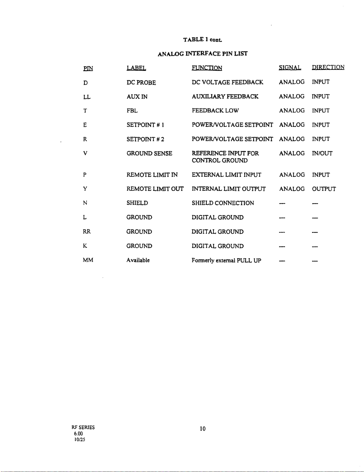
TABLE 1 cont.
ANALOG INTERFACE PIN LIST
LABEL
FUNCTION
SIGNAL
DIRECTION
DC PROBE
DC
VOLTAGE FEEDBACK ANALOG
INPUT
AUXIN
AUXILIARY
FEEDBACK ANALOG INPUT
FBL FEEDBACK LOW ANALOG INPUT
SETPOINT#
1
POWERNOLTAGE
SETPOINT ANALOG INPUT
SETPOINT#2
POWERNOLTAGE
SETPOINT ANALOG INPUT
GROUND SENSE REFERENCE INPUT
FOR
ANALOG IN/OUT
CONTROL GROUND
REMOTE LIMIT IN EXTERNAL LIMIT INPUT ANALOG INPUT
REMOTE LIMIT OUT INTERNAL LIMIT OUTPUT ANALOG OUTPUT
SHIELD SHIELD CONNECTION
GROUND DIGITAL GROUND
GROUND DIGITAL GROUND
GROUND DIGITAL GROUND
Available Fonnerly external PULL UP
10
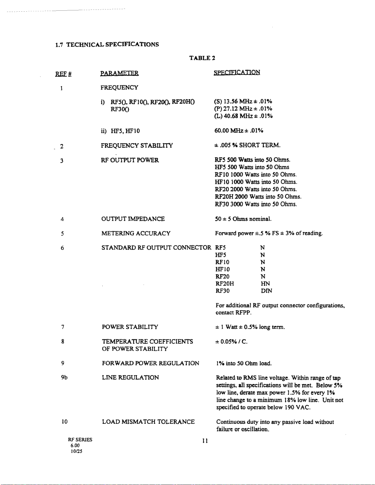
1.7
TECHNICAL
SPECIFICATIONS
2
3
4
5
6
7
8
9
9b
10
RF
SERIES
6.00
10/25
PARAMETER
TABLEl
SPECIEJCATION
FREQUENCY
i) RFSQ, RFI0Q, RF20(), RF20HO
RF30Q
ii) HF5,
HFl0
FREQUENCY STABILITY
RF OUTPUT
POWER
OUTPUT IMPEDANCE
METERING ACCURACY
(S) 13.56
MHz:1:
.01%
(P)27.12 MHz± .01%
(L)40.68
MHz:1:
.01%
60.00 MHz± .01%
± .005
•/4
SHORT TERM.
RFS
SOO
Wans
into
50
Ohms.
HFS
500 Watts into 50 Ohms
RFI0 1000 Watts into 50 Ohms.
HF10 1000 Watts into
SO
Ohms.
RF20 2000 Watts into
SO
Ohms.
RF20H 2000 Watts into 50 Ohms.
RF30
3000
Watts into
SO
Ohms.
SO
± S Ohms nominal.
Forward
power±.5
% FS ±
3%
of
reading.
STANDARD
RF
OUTPUT CONNECTOR
RFS
HFS
RFlO
HFIO
RF20
RF20H
RF30
N
N
N
N
N
HN
DIN
POWER STABILITY
TEMPERA
TIJRE
COEFFICIENTS
OF POWER STABILITY
FORWARD POWER REGULATION
LINE REGULATION
LOAD MISMATCH TOLERANCE
11
For additional
RF
output connector configurations,
contact
RFPP.
± J
Watt±
0.5% long term.
±0.05%/C.
I%
into 50 Ohm load.
Related to RMS line voltage. Within range
of
tap
settings,
all
specifications will be met. Below
5%
low line, derate max power 1.5% for every
I%
line change to a minimum 18% low line. Unit not
specified
to
operate below 190 V
AC.
Continuous duty into any passive load without
failure or oscillation.
I I
12
13
14
15
16
17
18
19
20
RF SERIES
6.00
10/25
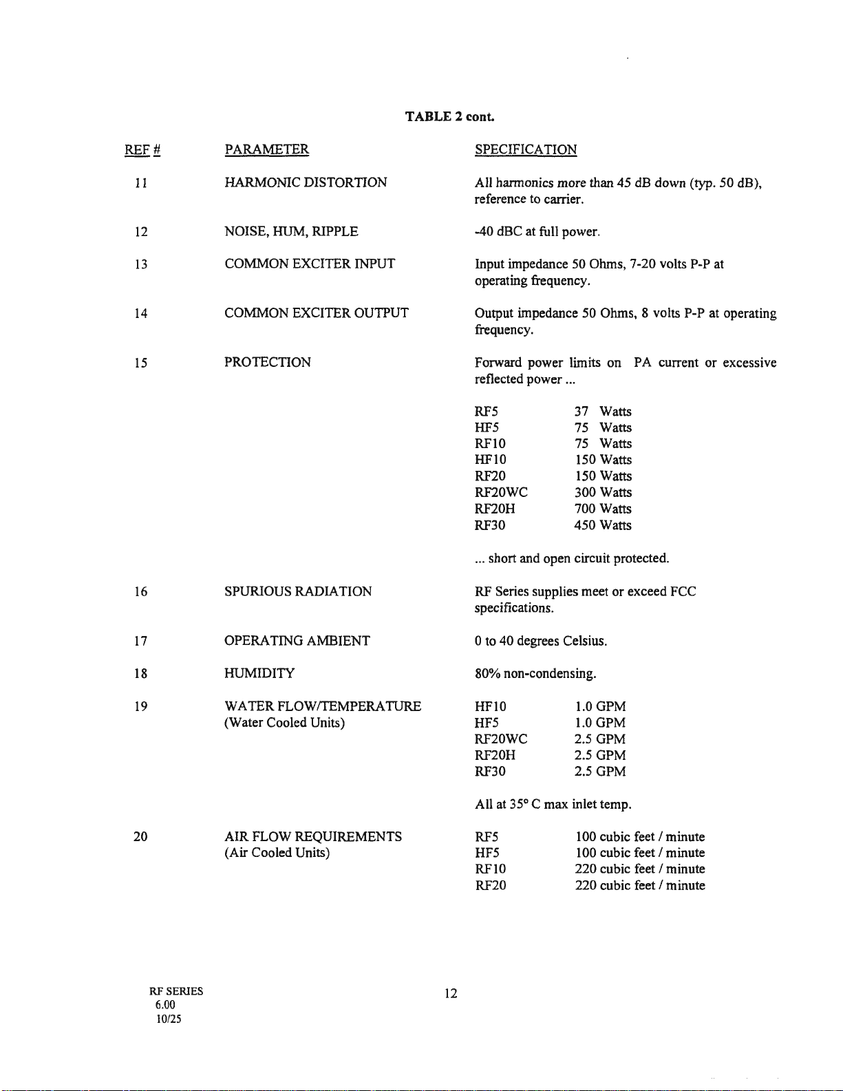
TABLE 2 cont.
PARAMETER
HARMONIC
DISTORTION
NOISE,
HUM,
RIPPLE
COMMON
EXCITER
INPUT
COMMON
EXCITER
OUTPUT
PROTECTION
SPURIOUS
RADIATION
OPERA
TING
AMBIENT
HUMIDITY
WATER
FLOWrrEMPERA
TURE
(Water
Cooled Units)
AIR
FLOW
REQUIREMENTS
(Air
Cooled
Units)
12
SPECIFICATION
All harmonics
more
than
45
dB
down
(typ.
50
dB),
reference
to
carrier.
-40
dBC
at
full power.
Input impedance 50 Ohms,
7-20
volts P-P at
operating frequency.
Output impedance
50
Ohms, 8 volts
P-P
at
operating
frequency.
Forward
power
limits
on
PA
current
or
excessive
reflected
power
...
RF5
37
Watts
HF5 75 Watts
RFlO 75 Watts
HFl0
150 Watts
RF20 150 Watts
RF20WC
300
Watts
RF20H
700 Watts
RF30
450
Watts
... short and
open
circuit protected.
RF Series supplies
meet
or
exceed
FCC
specifications.
0
to
40
degrees Celsius.
80%
non-condensing.
HFlO
HF5
RF20WC
RF20H
RF30
l.0GPM
1.0
GPM
2.5
GPM
2.5
GPM
2.5
GPM
All at 35° C
max
inlet temp.
RF5
HF5
RFlO
RF20
100 cubic feet / minute
100 cubic feet / minute
220
cubic feet / minute
220
cubic feet / minute
21
22
RF
SERIES
6.00
10/25
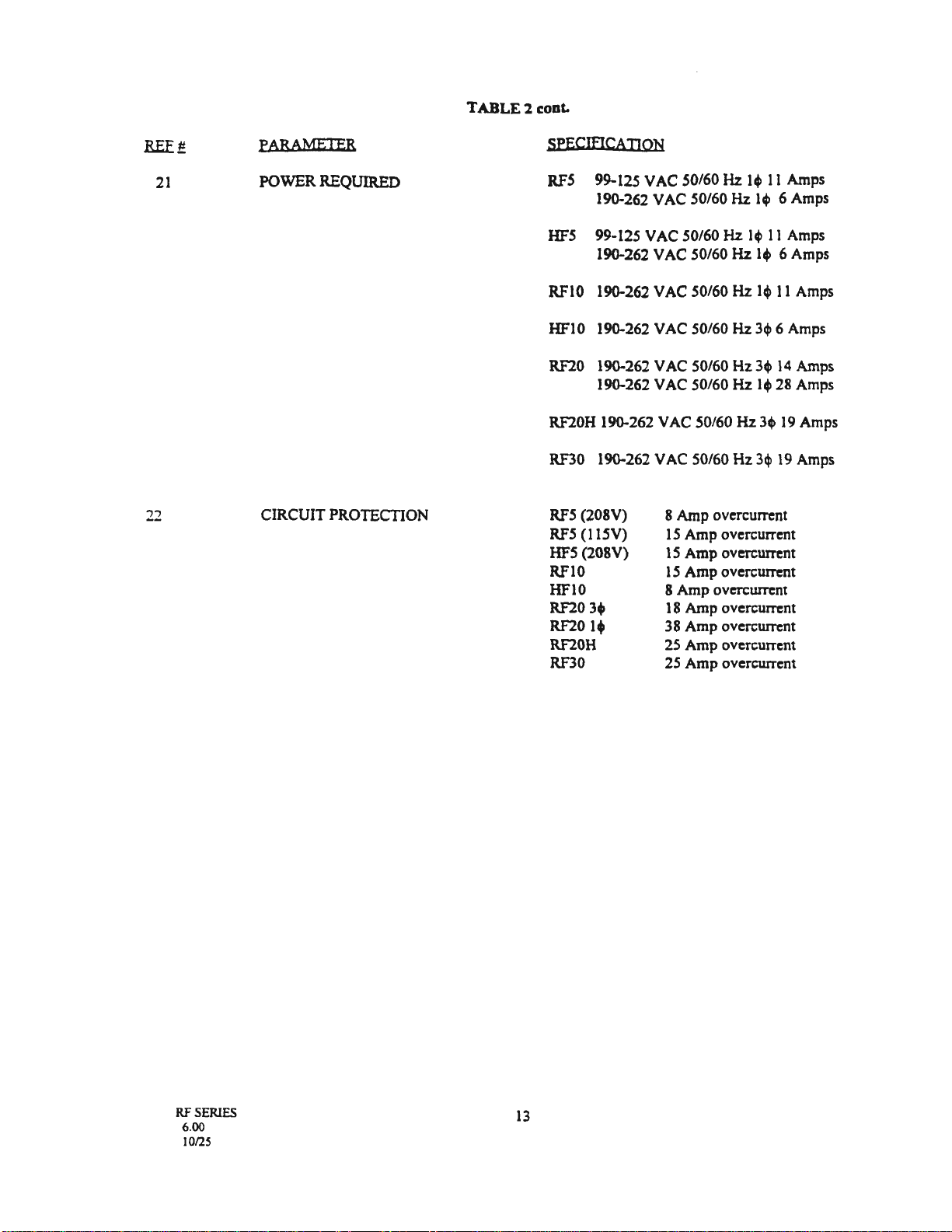
PARAMETER
POWER
REQUIRED
CIRCUIT
PROTECTION
TABLE 2 cont.
13
SPECIDCATION
RF5
99-125 V
AC
50/60 Hz 1+
11
Amps
190-262
VAC
50/60 Hz
14>
6 Amps
HF5
99-125
VAC
50/60
Hz
14>
11
Amps
190-262
VAC
50/60
Hz
14>
6 Amps
RFI0 190-262
VAC
50/60
Hz
14>
11
Amps
HFl0
190-262
VAC
50/60 Hz
34>
6 Amps
RF20
190-262
VAC
50/60
Hz34>
14
Amps
190-262
VAC
50/60
Hz
1+
28
Amps
RF20H 190-262 V
AC
50/60
Hz
34>
19
Amps
RF30
190-262 V
AC
50/60
Hz
3q>
19 Amps
RF5
(208V)
RF5
(115V)
HF5
(208V)
RFIO
HFlO
RF2034'
RF20
14'
RF20H
RF30
8
Amp
overcurrent
I5
Amp
overcurrent
15
Amp
overcurrcnt
l5
Amp
overcurrent
8
Amp
overcurrent
18
Amp
overcurrent
38
Amp
overcurrent
25
Amp
ovcrcurrent
25
Amp
overcurrent
This manual suits for next models
2
Table of contents
Other Advanced Energy Industries Power Supply manuals

Popular Power Supply manuals by other brands

Velleman
Velleman PSS13 Series manual

Eaton
Eaton APS3-330 Series Installation and operation guide

Keysight Technologies
Keysight Technologies RP7970 Series Operating and service guide

Ransburg
Ransburg 77070-33 Service manual

VOLTCRAFT
VOLTCRAFT SPS12-60W operating instructions

Kramer
Kramer VA-101P5 user manual


