manuals.online logo
Brands
  1. Home
  2. •
  3. Brands
  4. •
  5. Intermatic
  6. •
  7. Switch
  8. •
  9. Intermatic TimeMaster GM40 User manual

Intermatic TimeMaster GM40 User manual

INSTALLATION
1. Open door and then remove interior protective cover by releasing spring clip on bottom.
2. Remove timer mechanism by releasing spring clip on bottom.
3. Select knockouts to be used. Remove inner 1/2” knockout by inserting a screwdriver in
the slot and carefully punch knockout loose. Remove slug. If 3/4” knockout is required,
remove the outer ring with pliers after removing the 1/2” knockout. Smooth edges with
knife if necessary.
4. Place enclosure in desired mounting location and mark the three mounting holes (refer to
diagram). Start by placing set screw on top and attaching enclosure over keyhole; then
screw in remaining two screws on bottom.
5. Connect conduit hubs to conduit before connecting the hubs to the enclosure. After
inserting hubs into enclosure, carefully tighten hub lock nut. Do not over-torque.
6. Verify input voltage selection. Refer to DIP switch diagram for desired input voltage.
7. Wire in accordance with National and Local Codes (see wiring diagrams).
8. Grounding: Terminate all ground wires to ground lug on bottom of enclosure.
9. Replace interior protective cover.
Note: For outdoor locations, raintight or wet location conduit hubs that comply with require-
ments of UL 514B (standardfor fittings for conduit and outlet boxes) must be used.
6-1/8”
2-1/2”
File #E83486
Covered by U.S. Patent #6,563,2371.
Interior
Protective
Cover
Step 1
Diagram not to scale.
All dimensions in inches.
Ground Lug
Step 2
Timer Mechanism
GM40 General Purpose
Multi-Voltage Commercial
Time Switch
ELECTRICAL RATINGS:
N.O. Contacts:
40A Resistive @ 120~277VAC
1HP,16FLA, 90LRA @ 120VAC
2HP,12FLA, 52LRA @ 208~277VAC
30A Ballast @ 120VAC
20A Ballast @ 277VAC
15A Tungsten @ 120VAC
300VAPilot Duty 120~240VAC
N.C. Contacts:
30A Resistive @ 120~277VAC
1HP, 12FLA, 30LRA @ 120VAC
2HP, 10FLA, 30LRA @ 240VAC
2A Tungsten @ 120VAC
10A Ballast @ 277VAC
WIRING CONNECTIONS:
Screw box lug terminals
ENVIRONMENTAL RATINGS:
Operating Temperature Range:
–40°F to 131°F (–40°C to 55°C)
Operating Humidity: 0 to 95% non-condensing
ENCLOSURE DIMENSIONS:
8.795” x 6.631” x 2.935” (H x W x D)
SHIPPING WEIGHT: 2lbs.
4
3
2
1
ON
ON
ON
ON
120VAC
4
3
2
1
OFF
OFF
OFF
OFF
277VAC (Default)
4
3
2
1
OFF
ON
OFF
ON
208~240VAC
NOTE: Unit is shipped with DIP Switches set for 277VAC Input Voltage.
CAUTION: Do not check circuits by “sparking” wires to terminals. Damage to
the timer may result.
INPUT VOLTAGE DIP SWITCH SETTING:
1. Do not apply power to the GM40 prior to setting correct Input Voltage DIP switch.
2. Determine the input voltage which will be applied to the GM40 (i.e. L1 and L2/N terminals,
see wiring diagrams).
3. Set the DIP Switch according to the diagram below.
NEMA 3R Enclosure
Bracket
Mount with
Dimensions
2
APPLICATION
The GM40 Multi-Volt Series Time Controls are universal,
electromechanical time switches which can be field config-
ured for various power supply voltages. The voltage options
include 120VAC, 208/240VAC and 277VAC –all within the
same unit! Selection of the desired supply voltage is easily
achieved by selecting the DIP to the corresponding input volt-
age as indicated on the printed circuit board assembly (refer
to “input voltage selection” on page 1). The mechanism is
mounted in a NEMA 3R outdoor enclosure and has been
design for the control of lighting, heating, air conditioning,
pumps, motors, or general electrical circuits in residential,
commercial, industrial and agricultural facilities. All GM40
models are available as “Mechanism Only” (–M) for installation
in other enclosures or control panels or “Bracket Mount” (-B).
The GM40 is also available in a NEMA 1 Indoor Metal
Enclosure (-IM).
SPECIFIERS GUIDE
Furnish and install a Grasslin GM40 _ Multi-Volt Series 24 hour
or (7 day) time switch with captive trippers and quartz or syn-
chronous drive. Input voltage shall be 120, 208/240 or 277VAC
selectable via simple to set DIP switch. All units shall incorpo-
rate both SPDT and DPDT contacts that shall be rated at 40A,
2HP @ 277V. Toset the starting time and to provide time indi-
cation, the unit shall have an authentic clock face with hour
and minute hands. LED indicators shall provide Power and
Status feedback. Enclosure shall be NEMA 3R suitable for
both indoor or outdoor installation. Time switch shall contain
an OFF/AUTO/ON manual override. For Carry-over: The time
switch shall have a quartz drive with 7 day reserve carry-over.
PROGRAMMING INSTRUCTIONS
SETTING THE TIME: Rotate the program dial gradually
clockwise until the day of the week (7 day) and time of day
on the outer dial is nearly aligned with the triangle marker at
2o’clock position. Then set time to the minute by rotating
minute hand clockwise.CAUTION: Do not rotate dial or
minute hand counter-clockwise.
PROGRAMMING: The 24 hour model has trippers of 15
minute increments, and an AM/PM indication on the outer
dial. The 7 day model has trippers of 2 hour increments. The
outer dial shows the 7 days of the week and AM/PM for each
day. Push the captive trippers outward for the time period(s)
that the load is to be on (Normally open contacts closed).
MANUAL OVERRIDE: With the manual switch in the middle
position, the GM40 is in automatic mode and will switch at the
programmed times. In the upper position “I”, the load is per-
manently ON. In the lower position, “O”, the load is perma-
nently OFF
.
BATTERY POWERED RESERVE
(Quartz Models):
In case of power failure, the built-in nickel-cadmium battery
maintains the time of day for 7 days. During power outage
relays are de-energized.
The GM40 is the only electromechanical general purpose time switch that offers multi-voltage selection,
SPDT and DPDT contacts, 40Amp rating, indoor and outdoor enclosure – all standard in one model.
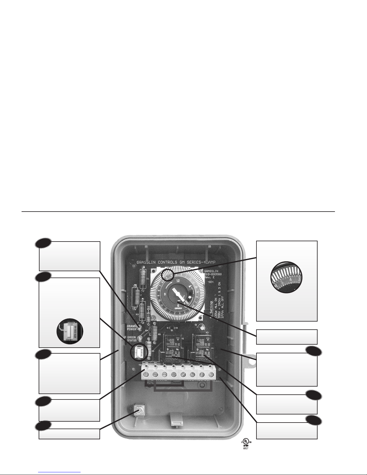
NO TOOLS REQUIRED!
Our “GUTS” simply snap
into existing Grasslin or
Intermatic enclosures
Moisture Resistant
Conformal Coated Board
Ground Lug Termination
Amber and Green
LED Lights Indicate
Power and Status
Large Screw
Terminals for Easy Wiring
#8 AWG
40 Amp Rated
Contacts
Captive Trippers
Can’t Be Lost
Independently
Adjustable Trippers at
15 Minute Intervals
Real-Time Clock Face
New Compact
VALOX®NEMA 3R
Outdoor Enclosure
Replaces All Metal
Enclosures
GM40 – 120, 208/240, or 277 Volts – The only one to stock.
Easy Multi-Voltage
Field Adjustable
DIP Switch for
120, 208/240,
or 277 VAC
File #E83486
Covered by U.S. Patent #6,563,237
NEW
NEW
NEW
NEW
NEW
NEW
NEW
NEW
GM40 TERMINAL DESIGNATIONS
GM40 TYPICAL WIRING DIAGRAMS
3
TIMER
120VAC
N
H
T
COM2NO2NC2
COM
NO
NCL2/NL1
LOAD
T
TIMER
120VAC
N
H
T
NO2NC2
NO
NCL2/NL1 COM COM2
LOAD
#1
T
LOAD
#2
N
TIMER
T
NO2NC2
NO
NC
L2/N
Normally Open
(Dry Contact)
Normally Closed
(Dry Contact)
L1
COM COM2
Normally Open
(Dry Contact)
Normally Closed
(Dry Contact)
TIMER
240VAC
L2
L1
T
COM2NO2NC2
COM
NO
NCL2/NL1
LOAD
T
Typical Wiring Diagram (120VAC Application)
Controlling One 120VAC Load
Typical Wiring Diagram (120VAC Application)
Controlling Two 120VAC Loads
Typical Wiring Diagram (240VAC Application)
Controlling One 240VAC (Dual Phase) Load
TIMER
277VAC
N
H
T
NO2NC2
NO
NCL2/NL1 COM COM2
LOAD
#1
LOAD
#2
T
ypical Wiring Diagram (277VAC Application)
Controlling Two 277VAC Loads
If GM40 is used to control a single 120VAC
load, remove jumper wire(L2/N to COM2) and
keep jumper wire (L1 to COM).
If GM40 is used to control two 120VAC loads,
remove jumper wire(L2/N to COM2) and
reposition it to (COM to COM2).
Note: GM40 is shipped with pre-
installed jumper wires (L1 to COM
and L2/N to COM2). In applica-
tions requiring a “DRY” non ener-
gized contact, remove jumpers as
shown.
If GM40 is used to control a single 240VAC
load, do not remove jumper wires
(L1 to COM and L2/N to COM2).
If GM40 is used to control two 277VAC loads,
remove jumper wire (L2/N to COM2) and
reposition it to (COM to COM2).
Note: Refer to page 1 for proper Input Voltage DIP Switch selection.
Trippers are “IN”
Indicates
Output is OFF
GREEN LED – OFF
Trippers are “OUT”
Indicates
Output is ON
GREEN LED – ON
GM40 TROUBLESHOOTING GUIDE
GM40 CONTACT TERMINALS TRANSITION
White arrow on timer module points to current time.
ORANGE
POWER
GREEN
STATUS
S1 Setting:
120V: ALL ON
200V - 240V: 1 & 3 ON
277V: ALL OFF
S1
GM40 MOUNTING INTO INTERMATIC ENCLOSURE
PROBLEM: LOAD (Lights/Pumps/Motor, etc.) does not turn ON
1. Check AMBER Power LED, if ON it indicates power is applied to GM40.
2. Verify correct input voltage DIP switch setting (refer to page 1).
3. Check voltage across terminals L1 and L2/N with Multi-meter.
4. Slide manual override switch (locate on right side of timer module) up. The
GREEN LED should illuminate indicating that the output should be ON.
5. Check wiring (refer to page 3).
PROBLEM: LOAD (Lights/Pumps/Motor, etc.)
does not turn OFF
1. Verify manual override switch is set to the middle
position.
2. Verify correct programming dial (refer to page 2).
3. Slide manual override switch (located on right side of timer module) down.
The GREEN LED should turn OFF indicating that the output should be OFF.
Mounting GM40 Mechanism into existing Intermatic
Metal Enclosure
The GM40 Series printed circuit board assembly will fit
into all Intermatic enclosures except the T7000 and
T5000 Series. Install GM40-M into Intermatic enclosure
in the same manner as the Intermatic mechanism was
previously installed.
AMBER LED
Illuminated when power is
applied to the GM40
GREEN LED
Illuminated when GM40
output is ON
TIMER
T
COM2NO2NC2
COM
NO
NCL2/NL1
TIMER
T
COM2NO2NC2
COM
NO
NCL2/N
L1
Status of Contacts
Note: Power must be applied across terminals L1 and L2/N in order for contacts to transition.
Status of Contacts
Intermatic, Inc.
7777 Winn Road
Spring Grove, IL 60081
www.intermatic.com

Other Intermatic Switch manuals

Intermatic T174CR Manual

Intermatic

Intermatic T174CR Manual

Intermatic IOS-DSIMF User manual

Intermatic

Intermatic IOS-DSIMF User manual

Intermatic ET70115C User manual

Intermatic

Intermatic ET70115C User manual

Intermatic CA600 User manual

Intermatic

Intermatic CA600 User manual

Intermatic T21004R Manual

Intermatic

Intermatic T21004R Manual

Intermatic T171CR Manual

Intermatic

Intermatic T171CR Manual

Intermatic ET100 SERIES Owner's manual

Intermatic

Intermatic ET100 SERIES Owner's manual

Intermatic ET2125C Manual

Intermatic

Intermatic ET2125C Manual

Intermatic RC2103S Quick start guide

Intermatic

Intermatic RC2103S Quick start guide

Intermatic T104 Manual

Intermatic

Intermatic T104 Manual

Intermatic IOS-DPBV-WH User manual

Intermatic

Intermatic IOS-DPBV-WH User manual

Intermatic T1975E Manual

Intermatic

Intermatic T1975E Manual

Intermatic T1975BCR Manual

Intermatic

Intermatic T1975BCR Manual

Intermatic ET2105C Manual

Intermatic

Intermatic ET2105C Manual

Intermatic T1975 Manual

Intermatic

Intermatic T1975 Manual

Intermatic ET1100 Series Guide

Intermatic

Intermatic ET1100 Series Guide

Intermatic T1471BCR Manual

Intermatic

Intermatic T1471BCR Manual

Intermatic FM1D20A-24 User manual

Intermatic

Intermatic FM1D20A-24 User manual

Intermatic T1905 Manual

Intermatic

Intermatic T1905 Manual

Intermatic T171 Manual

Intermatic

Intermatic T171 Manual

Intermatic T2005 Manual

Intermatic

Intermatic T2005 Manual

Intermatic T105 Manual

Intermatic

Intermatic T105 Manual

Intermatic RC2403RT Service manual

Intermatic

Intermatic RC2403RT Service manual

Intermatic T7401BC Manual

Intermatic

Intermatic T7401BC Manual

Popular Switch manuals by other brands

3Com 3CRS48G-24-91 datasheet

3Com

3Com 3CRS48G-24-91 datasheet

LEGRAND 7 521 83 manual

LEGRAND

LEGRAND 7 521 83 manual

Innon OC-7N1016 user manual

Innon

Innon OC-7N1016 user manual

Schwaiger DiSEqC Multiswitch Installation information

Schwaiger

Schwaiger DiSEqC Multiswitch Installation information

LevelOne FSW-1609TFX user manual

LevelOne

LevelOne FSW-1609TFX user manual

ATEN KVMP CS1782A quick start guide

ATEN

ATEN KVMP CS1782A quick start guide

Beck Climair 930.8 Series quick start guide

Beck

Beck Climair 930.8 Series quick start guide

Hisense HCHM-N04X installation manual

Hisense

Hisense HCHM-N04X installation manual

Ubiquiti USW--Pro--48 quick start guide

Ubiquiti

Ubiquiti USW--Pro--48 quick start guide

Emerson Rosemount 2535 quick start guide

Emerson

Emerson Rosemount 2535 quick start guide

Lutron Electronics Maestro MS-OPS5M manual

Lutron Electronics

Lutron Electronics Maestro MS-OPS5M manual

IPGARD SDVN-2D user manual

IPGARD

IPGARD SDVN-2D user manual

Kohler KCS Operation and installation

Kohler

Kohler KCS Operation and installation

Adler ASM312 INSTALLATION, MAINTENANCE AND OPERATING MANUAL INSTRUCTION

Adler

Adler ASM312 INSTALLATION, MAINTENANCE AND OPERATING MANUAL INSTRUCTION

ZyXEL Communications ES-2024 Series user manual

ZyXEL Communications

ZyXEL Communications ES-2024 Series user manual

ALFAtron SC51TS user manual

ALFAtron

ALFAtron SC51TS user manual

Avocent DSR Series DSR1022 brochure

Avocent

Avocent DSR Series DSR1022 brochure

Veris Industries Hawkeye 735 installation guide

Veris Industries

Veris Industries Hawkeye 735 installation guide

manuals.online logo
manuals.online logoBrands
  • About & Mission
  • Contact us
  • Privacy Policy
  • Terms and Conditions

Copyright 2025 Manuals.Online. All Rights Reserved.