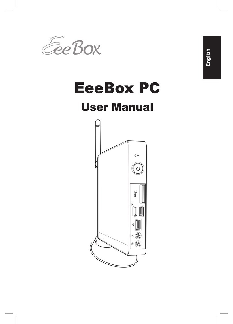
Intermec 5055 User manual

5055 DataCollection PC
USER’SGUIDE
""""""""""""""""""""""""""""
PN:961-054-017
Revision A
May1999

"NOTICEThispublication containsinformation proprietarytoIntermec TechnologiesCorporation.It is
being suppliedto you withthe express understanding that theinformation contained hereinis
forthebenefit ofthe contracting party only,and may notbe copied,distributed,ordisplayedto
third partieswithout the express writtenconsentofNorand Corporation,and shall bereturned
toIntermec TechnologiesCorporation upon writtenrequest.If apurchase,license,ornondis-
closure agreementhasbeenexecuted,thetermsofthatagreementshall governthisdocument.
Thispublication isfurnishedforinformation only,and theinformation init is subject tochange
withoutnotice.Although everyefforthasbeenmadeto provide complete and accurate
information,Intermec TechnologiesCorporation assumesno responsibility orliabilityforany
errorsorinaccuraciesthatmayappearinthisdocument.
Wewelcomeyourcommentsconcerning thispublication.Although everyefforthasbeenmade
to keepit free oferrors,somemay occur.Whenreporting aspecificproblem,pleasedescribeit
brieflyand includethebook title and partnumber,aswell astheparagraph or figurenumber
and thepagenumber.
Send yourcommentsto:Intermec TechnologiesCorporation
Norand MobileSystemsDivision
PublicationsDepartment
550 Second StreetSE
CedarRapids,Iowa52401
ÒRegisteredtrademark;Marca Registradaby Norand Corporation,CedarRapids,Iowa,U.S.A.
ÓCopyright1999,Intermec TechnologiesCorporation.All rightsreserved.
Acknowledgements
Ethernetisatrademark ofXerox Corporation.
Pentiumisatrademark of IntelCorporation.
PS/2isatrademark of IBMCorporation.
MICRO-CLEANII isaregisteredtrademarkofForesightInternational,Inc.
Microsoft,MS,MS-DOS,andWindowsareregisteredtrademarksandVisualBasic
forWindows,andWindowsforPenaretrademarksofMicrosoftCorporation.
SanDiskisatrademarkofSanDiskCorporation.

CONTENTS
5055 DataCollection PC User’sGuide i
CONTENTS
""""""""""""""""""""""""""""
SECTION1
General Information
About thisManual1-1...................................
Section1 1-1........................................
Section2 1-1........................................
Section3 1-1........................................
Section4 1-1........................................
RelatedPublications1-2..............................
GeneralInformation1-2.................................
Installation1-2......................................
MobileComputer:HowitWorks1-3..................
TheComputer1-4.......................................
TheDisplay1-5.....................................
Connectors1-6......................................
Speakers1-7.....................................
Microphone1-7..................................
Keyboard/Mouse1-7.............................
LPT1-- (PrinterPort)1-7.........................
DCPowerInput1-7..............................
On/Off Switch1-7................................
COM1,COM2(SerialPorts)1-7...................
Headphone1-8..................................
NetworkConnection(NET)1-8....................
Card/DriveSlots1-8.................................
IDEDriveBay1-8...............................
PC CardSlots(PCMCIA)1-8......................
RadioAntennaConnectors(RF)1-8................
AC-DCPowerSupply1-10.............................
Maintenance1-12........................................
Cleaning1-12........................................
DailyChecks1-12....................................
Specifications1-14....................................

CONTENTS
ii 5055 DataCollection PC User’sGuide
SECTION2
Operation
Introduction2-1.........................................
StartupRequirements2-1...............................
StartupSequence2-2....................................
Options2-2.............................................
HardDriveInstallation2-2...........................
SANdiskDriveInstallation2-4.......................
PC CardInstallation2-6.............................
RadioInstallation2-8................................
InternalAntennaCableInstallation2-8............
AntennaInstallation2-9..........................
MultipleAntennas2-10............................
ExternalAntennaCable2-11......................
AntennaBracketInstallation2-12..................
ConnectorCover2-13..............................
DesktopMountOption2-14........................
PC(PCMCIA)Cards2-15.................................
RemovingPC Cards2-15..............................
PatchAntenna 2-16......................................
Start-up2-17............................................
InstallingSoftware2-17..................................
ExternalDrives2-17..................................
DownloadingfromaNetwork2-17.....................
Restart(or,“Reboot”)2-18.................................
WarmRestart2-18....................................
ColdRestart2-18.....................................
AvailableTetheredScanners2-19..........................
SymbolScanners2-19.............................
PSCScanners2-19................................
InstalledScannerSoftware2-20...........................
SettingTerminalEmulation2-20.......................
SettingDOSApplications2-21.........................
SettingRS-232 Parameters
(forSymbolLS3203 orLS3603 scanners)2-21.......
SetAll Defaults2-21..............................
DataTransmissionFormat2-22....................
RS-232 HostPrefix/SuffixValues2-23...............
RS-232 HostParity2-24...........................
RS-232 HostStopBitSelect2-24...................

CONTENTS
5055 DataCollection PC User’sGuide iii
RS-232 HostASCII Format2-24....................
RS-232 HostTransmitCodeIDCharacter
(Optional)2-25................................
RS-232 HostDecodeOptions2-25..................
ScannerProblems2-26............................
SECTION3
SystemSetup
Introduction3-1.........................................
SystemConfigurationUtility3-2.........................
BootDevices3-2.....................................
Components3-3.....................................
COMPorts3-4...................................
MouseDisable3-5...............................
DisplayInvert3-5................................
SECTION4
ConnectorPinouts
FIGURES
Connectors4-1..........................................
ParallelPrinterPort4-2.................................
COMSerialPorts(COM1,COM2)4-3.....................
KeyboardandMousePorts4-4....................
10BASE-TInterface4-5..........................
Figure1-1TheDataCollectionPCNetwork1-3............
Figure1-2Intermec5055 DataCollectionPC
(frontview)1-5......................................
Figure1-3Connectors1-6................................
Figure1-4DrivesandAntennaConnectors1-9............
Figure1-5AC-DCPowerSupply1-10......................
Figure1-6DC-DCPowerSupply1-11......................
Figure2-1HardDriveAdapter2-3.......................
Figure2-2SANdiskJumper2-4..........................
Figure2-3SANdiskDriveAdapter2-5...................
Figure2-4DriveBays2-7...............................
Figure2-5AntennaInstallation2-9......................
Figure2-6MultipleAntennas2-10........................

CONTENTS
iv5055 DataCollection PC User’sGuide
Figure2-7AntennaCableChannelCover2-11.............
Figure2-8Antenna andBracketAssembly
(Installed)2-12......................................
Figure2-9ConnectorCover2-13..........................
Figure2-10 DesktopMountOptions2-14..................
Figure2-11 DriveandPC CardRemoval2-15..............
Figure2-12 AntennaPolarization2-16....................
Figure4-1Connectors4-1................................
TABLES
Table5-1ParallelPort(LPT1)Pinout4-2.................
Table5-2SerialCommunicationPorts(COM1/COM2)4-3. .
Table5-3SerialCommunicationPortPinouts4-3..........
Table5-4Keyboard/MousePortPinouts4-4...............
Table5-5RJ-45 Pinouts4-5..............................

5055 DataCollection PC User’sGuide 1-1
Section 1
General Information
""""""""""""""""""""""""""""
About thisManual
ThisUser’sGuidecontainsaproductintroductionandGen-
eralInformation, OperatingInstructions,SystemFeatures,
andConnectorPinouts.Softwareinstructionsarenotin-
cludedinthismanual
Section 1
TheGeneralInformationsectionismostusefultothe end
user.ItdescribestheON/OFF switch,cableconnections,
display,andotherfeaturesofthecomputer.
Section 2
This sectionprovidesbasicinformationforusingthecom-
puter,andtheaccessoriesandoptionsavailableforit.
Section 3
TheSystemSetupsectionisintended primarilyforthesys-
temprogrammer;this sectiondescribesdetailsofyour com-
puterandmethodsfor customizingit toyourspecificneeds.
CMOSsetupinstructionsareincludedhere.
Section 4
This sectionprovidesconnectorpinoutinformation.

SECTION 1"GeneralInformation
1-25055 DataCollection PC User’sGuide
RelatedPublications
"VehiclePower SupplyInstallationInstructions,
(P/N962-054-004).
"Intermec5055 DataCollectionPCTechnicalReference
Manual,(P/N978-054-002)
"http://www.intermec.com/manuals/manuals.htm
General Information
TheIntermec5055 DataCollectionPCisapowerfulreal-
timecomputerdesignedforwarehouseandautomatedma-
terialhandlingenvironments.Althoughthecomputeris
intendedfordatacollection,itcontainsamodern high-
speedPentiumtprocessorandhasfull PCcapabilities. De-
pendinguponyour requirements,thiscomputermaybe
equippedwithanintegratedradiofortotalmobility.The
standardEthernetonboardallowshardwireconnectionto
alocalareanetwork(LAN).
All computerelectronics,theradiomodule,andthelarge
displayarehousedwithinasinglemetalcontainer.Adc-dc
power converter canberemotelymountedonavehicleto
ensureastablepowersourceinmobileapplications.Fixed-
mountcomputers(i.e., thoseconnectedtoalocalareanet-
work)haveaseparateac-dcpowersupply.
Installation
TheIntermec5055 DataCollectionPCinstallseasilyon
verticalorhorizontalsurfacesusingone ofseveraladjust-
ablemountingbrackets.

SECTION 1"GeneralInformation
5055 DataCollection PC User’sGuide 1-3
MobileComputer:How itWorks
Wireless datacollectionPCsare“real-time”devicesbecause
thecomputertracksinventorymovementonthego.When
youenterdataintotheunit,theintegratedradiomodule
transmitsthatinformationtoa baseunitoraccess point.
From there,informationgoestoahostcomputer.Ifthe
entrywasarequestforinformation,thehost transmitsthe
responsetothecomputerthat madetherequest.These
real-timedatatransactionsensurethat themostcurrent
informationisavailabletothehostcomputerandtoall mo-
bileunits.Figure 1-1showsa basicLANsystem toaidyour
understandingofthelocalareanetworkconcept.
Figure 1-1
TheDataCollection PC Network
Network
ManagementStation
(server)
Ethernet (distribution)
LAN
Access
Point
Access
Point
MobileMount
DataCollection PC
Fixed-MountComputer
(hardwiredto LAN)

SECTION 1"GeneralInformation
1-45055 DataCollection PC User’sGuide
TheComputer
Theillustrationsinthis sectionwill familiarizeyouwith
externalfeaturesoftheIntermec5055 DataCollectionPC.
Figure 1-5showstheACPower Supplyusedwithfixed-
mountunits, whileFigure 1-6showstheDC-DCPower
Converter usedinmobilemountinstallations.
All connectorsthatarepartofthecomputersystemarede-
scribedindetail inSectionFourofthismanual.
Thelistbelowispresentedheresothatyouwill notice
theseitemsastheyareshowninthefollowingpages.This
listisrepeatedinSection2becausemanyoftheproblems
youarelikelyto encountermayresultfromoverlookingone
ormore oftheseitems.
Eachworkdaymakesurethat:
"Mountingknobsaretight.
"TheDCpower inputcableis secure.
"TheDCpower outputcableis secure.
"TheACpower supply(fixed-mount)ispluggedintothe
wall.
"TheOn/Off switchisON (press the1side ofthe
switchto enablepower).
"Theantennaconnector(s) (ifso equipped)is secure.
"TheLANconnector(ifso equipped)is secure.
"Thescanner cable(ifso equipped)is secure.
"LPT1,theprinter cable(ifso equipped)is secure.

SECTION 1"GeneralInformation
5055 DataCollection PC User’sGuide 1-5
TheDisplay
Thedisplaycanbebothaninputandanoutputdevice,be-
causeyoucantouchit tomake entries(input)anditdis-
plays(outputs)information.Thetouchscreenrequiresdi-
rectpressuretodetectyourentriesormenu selections.
Figure 1-2
Intermec 5055 DataCollection PC
(frontview)
1.Display
1

SECTION 1"GeneralInformation
1-65055 DataCollection PC User’sGuide
Connectors
TheOn/Off switchandall connectorsarelocatedonthebot-
tomoftheunit.Theseincludeapower connector,antenna
connectors,LPT1parallel input-output(I/O)connector,two
standardserialI/O connectors(COM1andCOM2),akey-
board(KYBD)connector,anetwork(NET)connector,and
dualPCMCIA(PC Card)slots(see Figure 1-4).
Figure 1-3
C
o
n
n
e
c
t
o
r
s
1.Speakers
2.Microphonejack (audioIN)
3.6-pinminiDIN(PS/2mouse)
4.LPT1(printer)
5.DC powerinput
6.On/Off switch
7.COM2(RS-232 w/5Vdc)
8.COM1(RS-232 w/5Vdc)
9.6-pinminiDIN(PS/2 keyboard)
10.Headphonejack (audioOUT)
11.Network
6
8
9
123
4
5
7
11
1
10

SECTION 1"GeneralInformation
5055 DataCollection PC User’sGuide 1-7
Speakers
SpeakersareprovidedtoallowstandardPC/ATsounds,as
well asbusiness audiotoplayandrecord.
Microphone
This3.5mm connectoracceptsanexternalmicrophone.
Keyboard/Mouse
Locking6-pinmini-DINconnectorsaccommodateanexter-
nalPS/2standardmouse(3)andkeyboard(9). OnlyPS/2
deviceswithlockingconnectors shouldbeusedonmobile
mountedterminalsto ensureagainstunwanted disconnec-
tion.PS/2deviceswith non-lockingconnectorscanbeused
withfixed-mount terminals.
LPT1- (PrinterPort)
Thisisanenhanced parallelportwitha 25-pin(DB-25)fe-
male, D-subminiatureconnectorforparalleldevices.
DC PowerInput
Thisisa 3-pincircular connectorwhichisthreadedtore-
ceiveapower cableconnectorthathasalockingcollar.A
regulated+12 voltpowersupply/converterisrequired.
On/Off Switch
"NOTE:ALWAYS performa propersystem(orWindows)shut-down before
shutting the computerOFF.
This switchislocatedonthebottomoftheunitnext tothe
DCpowerinputconnector.Alwaysdisable(press the“0”
side oftheswitchtodisable)powerwhenconnectingordis-
connectingcablesandaccessories.
COM1,COM2(SerialPorts)
Eachporthasitsownaddress anda 9-pinmaleconnectorto
attachRS-232 serialdevices.COMportscanprovide5
voltsdctosupportadecodingtypetetheredscanner.

SECTION 1"GeneralInformation
1-85055 DataCollection PC User’sGuide
Headphone
This3.5mm connectoracceptsanexternalheadphone.
NetworkConnection (NET)
TheIntermec5055 DataCollectionPChasEthernet
(10BASE-T,RJ-45 jack)onboard.
BCAUTION:Use spinning-mediaPC Cardsforfixed-mountapplicationsonly.
WARNING:Bothedges ofPCcardsmustbeinthe correctgrooves inthe
drive toavoid damagetothe card ortothe computer.
WARNING:To preventdamaged pins,do NOTforce PCcardsortheIDE
drive intotheir respective slots.
Card/Drive Slots
Removetheantennaconnectorpaneltoaccess thecard/
driveslots.Whenreinstallingthepanel,carefullydress an-
tennacablesintotheslotstoguardagainstdamagingthem.
IDEDrive Bay
Aspecialmetalcarrieradaptsmostcurrentlyavailable
miniature(2.5inch)IDEtypedrivestothisbay.Themetal
carrierhasatab thatsecurelyholdsthedriveinplace.
PC CardSlots(PCMCIA)
Theseuser-accessibleslots(0 and1)areforPC Card de-
vices.Each68-pinslotcanaccomodateaTypeI,II,orIII
device.
RadioAntennaConnectors(RF)
All connectorlocationsareshown,howeverone ormore of
them maybeplugged dependingupontheradio(s)inyour
computer.Thecomputerhasanantennamountingbracket
at thetopoftheunit.

SECTION 1"GeneralInformation
5055 DataCollection PC User’sGuide 1-9
1
1. IDEdrive bay
2.PCcardslot0
3.PCcardslot1
4.Antenna connectorpanel
2 3
Figure 1-4
Drives and AntennaConnectors
4
See
Caution
CAUTION
To avoid damaging theunit
DoNOTremove thefourscrews shownincircles.

SECTION 1"GeneralInformation
1-10 5055 DataCollection PC User’sGuide
AC-DC PowerSupply
"NOTE:ALWAYS performa propersystem(orWindows)shut-down before
shutting the computerOFF.
Theacpowersupplyshownbelowdoes NOThaveanOn/Off
switch:todisablepowertoafixed-mount5055 Computer,
usetheOn/Off switchonthecomputeritselforunplugthe
AC power cablefrom thewall outlet.
1.DC powercord
2.AC powercordconnector(notvisible)
Figure 1-5
AC-DC PowerSupply
12

SECTION 1"GeneralInformation
5055 DataCollection PC User’sGuide 1-11
WARNING:Make sure you have the correctpowerconverterforyour
application.See Specificationsforinputvoltageranges.
Model:851-040-001 P/N:066776-01
10--36 V;10 A
Model:851-041-001 P/N:066777-01
15--96 V;5.5A
InputConnector
OutputConnector
Green LED
(poweroutputindicator)
""
""
""
""
Figure 1-6
DC-DC PowerSupply

SECTION 1"GeneralInformation
1-12 5055 DataCollection PC User’sGuide
Maintenance
Yourterminalrequiresverylittlemaintenance.Cleanthe
terminalandthedisplayperiodically,and perform thedaily
checkslistedbelow. Ifafailuremessageappearsonthedis-
play,thecomputermayneedtobesent toanauthorized
servicefacilityfor repairoradjustment.
Cleaning
Arecommendedcleanerforthe exterioroftheMobile
MountRadioDataComputerisMICRO-CLEANIICleaner,
madebyForesightInternational,Inc., 4887 FStreet, Oma-
ha,Nebraska 68127-0205 (phone:1-800-637-1344).
BCAUTION:Do notpourany cleanerdirectlyon thedisplay.
BCAUTION:DoNOT useawater-basedcleaneron thedisplay.
BCAUTION:Use ethanol-basedcleanersONLYon thedisplay.
"NOTE:Keep the displayarea clean and free ofdust, dirt, grime orsmudges.
Failuretodosocan resultin unreliabletouch entries.
Useasoft,lint-free clothdampenedwithethanolalcoholto
toremovedirtorfingersmudgesfrom thedisplayarea.
DailyChecks
Eachworkday youshouldchecktomakesurethat:
"All antennaconnectorsaresecure.
"All mountingknobsaretight.
"Thepower cableis secure.
"Thescanner cableis secure.

SECTION 1"GeneralInformation
5055 DataCollection PC User’sGuide 1-13
FactoryService
Iftheunitisfaulty,youcanshipit toyournearestautho-
rizedServiceCenterforfactory-qualityrepairservice.
Theiraddress andtelephonenumber canbefoundonthe
ProductServiceInformationCard.
Whenproductsmustbeshippedfor repair:
"Makesurethatall antennasareremoved.
"Packageinoriginalshippingcartonifpossible.
"Fill outaProductServiceInformationCardandin-
cludethiscardwiththeproduct.
Ifthe originalshippingcontainerisnotavailable,appropri-
atepackagingmaterialscanbesubstituted.Ifindoubt,
contactyour regionalCustomerSupportSpecialistfor
instructions.
ProductService Information Card
Ifrepairsarenecessary,fill out theProductServiceInfor-
mationCardandsenditinwiththeunit.Besuretoin-
cludea briefdescriptionoftheproblem(s)whenyoureturn
theproductfor repair.Anewcardisincludedwhenthere-
paired productisreturnedtoyou.
FactoryService
Youcanphone orwritethefactoryat thefollowinglocation
forspecificserviceinformationabout thisproduct:
IntermecTechnologiesCorporation
NorandMobileSystemsDivision
Attn:ServiceCenter
4217 Mt.VernonRoadS.E.
CedarRapids,Iowa 52403
1-800-755-5505

SECTION 1"GeneralInformation
1-14 5055 DataCollection PC User’sGuide
Specifications
Physical
Size12”x9.35”x2.125” top/3.775”bottom(w/h/d)
Weight7--9lbs(approximate,dependingonconfiguration)
Environmental
OperatingtemperatureELdisplay:--22 to+122 °F(--30 to+50 °C)
all displays:--4to+122 °F(--20 to+50 °C)
Storagetemperature--40 to+185 °F(--40 to+85 °C)
Humidity0to95%noncondensing
Electrical
PowerSourcesexternal,dc-dc converter(vehicleinstallations)
auto-ranginginput
12 Vdc regulatedoutput
twomodels:10.0-- 36 Vdcinput/54wattsmax., or
15 -- 96 Vdcinput/54 wattsmax.
120 Vac,60 Hz,0.8ampinput,12 Vdcoutput,3.0amps
Communication6-pinmini-DIN(PS/2 keyboardand mouse connectors)
(I/Oconnections)9-pinD-sub(twoRS-232Cserialportconnectors)
25-pinD-sub(parallelportforprinter,diskdrive,etc.)
RJ-45 jack(localareanetworkEthernetconnection)
audiopinjacks(earphoneand microphone)
StandardsFCC Class B,TUV RFImark,DOC,SCyTm,UL1950,
CULC22.2950,variousCE marks
ProcessorPentium,133 MHz(standard)
L-2Cache512K(standard)
StandardMemory64-bitSDRAM(standard),optionsfrom8--64 MB
FlashMemory256K(standard)
PC Cardoptionstwov2.0PCMCIAtypeIII slots
oneinternaltypeIII IDEdriveslotavailable
Displays640 x480 colorTFT (standard)
640 x480 wide-temperaturemonochromeEL(optional)
800 x600 colorTFT (optional)
TouchscreenResistive
(supportsmenu and mouse-drivenapplications)
Compatibility
SoftwarefullyPC-compatible,industrystandardenvironment
OperatingSystemsMS-DOSorWindowsoptions
Other manuals for 5055
4
Table of contents
Other Intermec Desktop manuals
Intermec
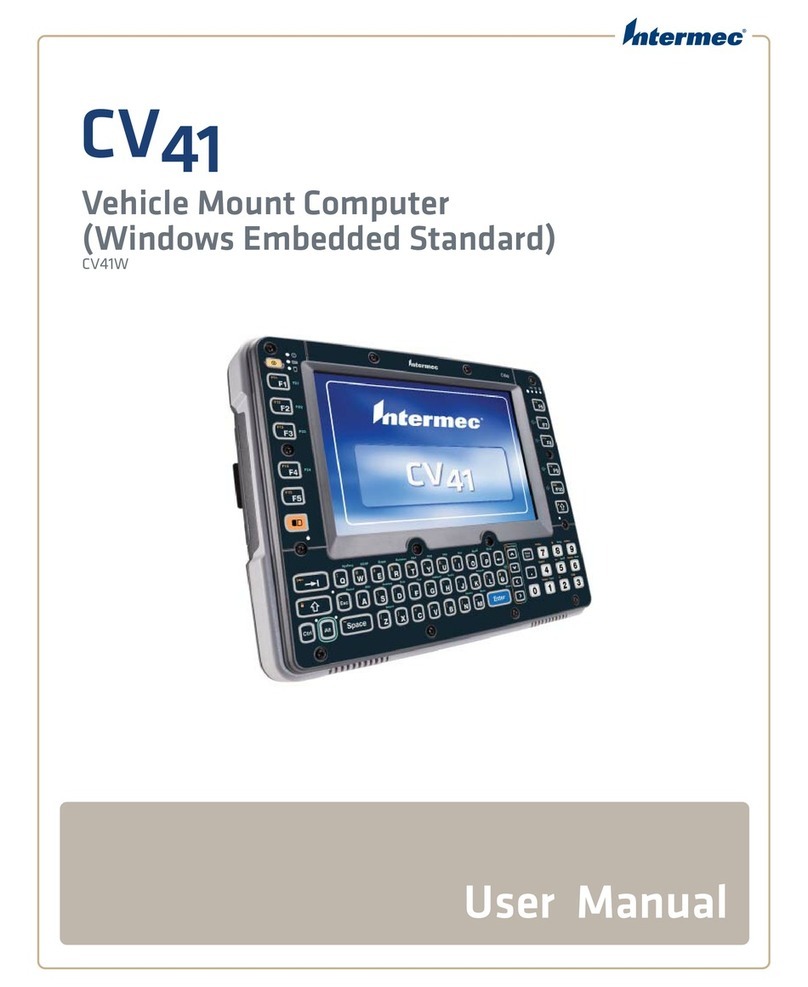
Intermec CV41 User manual
Intermec
Intermec CV60 User manual

Intermec
Intermec CV60 User manual
Intermec
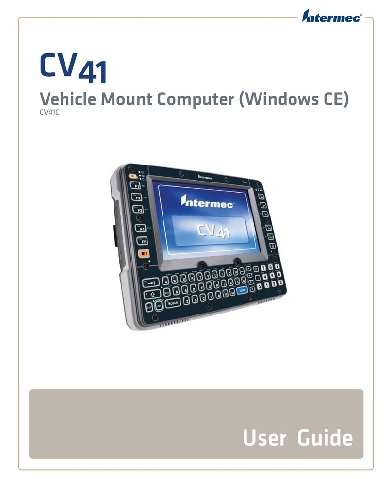
Intermec CV41C User manual

Intermec
Intermec CV60 Quick start guide
Intermec
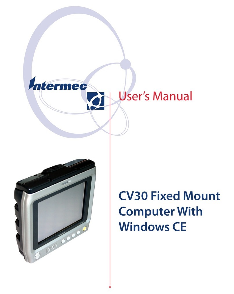
Intermec CV30 User manual

Intermec
Intermec 3596 User manual

Intermec
Intermec CV60 User manual
Intermec
Intermec NORAND 6642 User manual

Intermec
Intermec CV30 User manual


