Page 8 of 30
Step 7
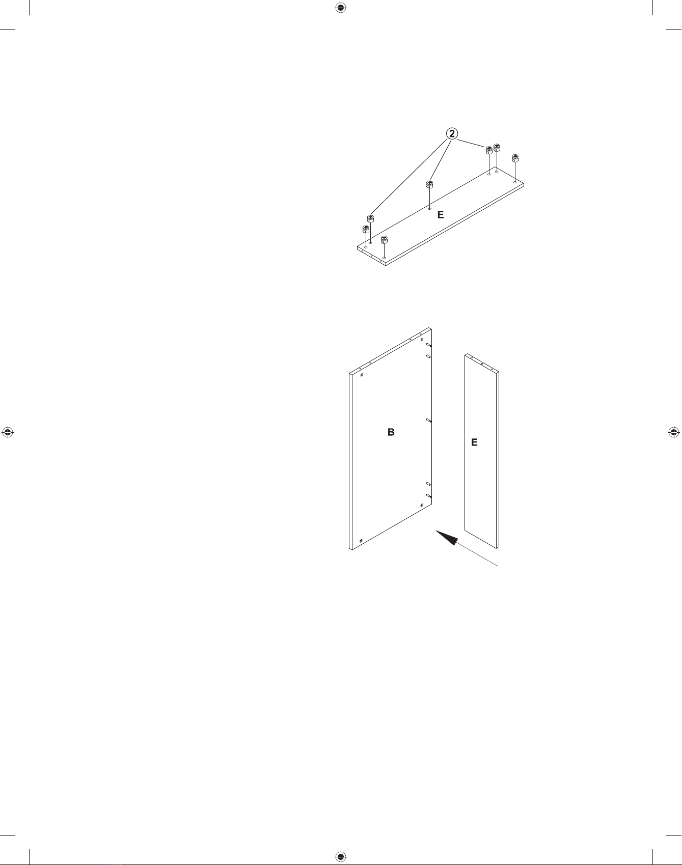
Attach the Back Panel (B) and
Small Shelf Panel (E) to the Left
Side Panel (C) as shown on the
drawing ensuring that the Cam
Screw (1) properly engage with the
Cam Lock (2)
With a Phillips Screw Driver
rotate the cam lock 1/2 turn
clockwise until snug. DO NOT
OVERTIGHTEN
Step 8
With the Right Side Panel (D)
laying on a non-abrasive surface
insert with a Rubber Mallet 5 each
Wood Dowel (4) in the position
shown on the drawing.
With a Phillips Screw Driver,
insert 6 each Cam Screw (1) in the
position shown on the drawing.
Install the Right Keyboard Rail (8)
to the Right Side Panel (C) with 3
each 4X10 Screw (5). See inset for
proper hole position.
Small shelf panel
Back panel
Table panel
Left side panel
Right side panel
LLR60138_60139_Manual_ENG.indd 9LLR60138_60139_Manual_ENG.indd 9 3/4/11 4:10 PM3/4/11 4:10 PM