U-Line Deluxe H-6851 User manual

PAGE 1 OF 38 1021 IH-5759
1-800-295-5510
uline.com
DELUXE WORKSTATIONS
PARTS
TOOLS NEEDED
Phillips Head
Screwdriver
Flathead
Screwdriver
Allen Wrench
(included)
Electric
Drill
1/4" Drill Bit
5/32" Drill Bit
7/16" Wrench
3/8" Wrench
10 mm Wrench
2
1
6
6
5
48
9
3
2
7
1
1
11
12
2
1
1
1
10
Para Español, vea páginas 13-25.
Pour le français, consulter les pages 26-38.
ADD-ON UNIT FOR
L-SHAPED WORKSTATION
DELUXE WORKSTATION
If purchased a packing station, please use the
instructions packaged with the lower shelf.
If purchased a cabinet workstation, please use
instructions packaged with cabinet frame.
CAUTION! Some parts may have sharp edges.
Care must be taken when handling various
pieces to avoid injury. For your safety, wear a
pair of work gloves when assembling.

PAGE 2 OF 38 1021 IH-5759
PARTS CONTINUED
Hardware Kit
Lock Washer
(Non-Steel Top)
Deluxe Workstation
60" & 72" x 8
96" x 12
L-Shaped Workstation
72 x 78" x 16
96 x 78" x 20
1/4-20 Nut
(Non-Steel Top)
Deluxe Workstation
60" & 72" x 16
96" x 28
L-Shaped Workstation
72 x 78" x 24
96 x 78" x 36
Locking Tab
Deluxe Workstation
60" & 72" x 4
96" x 6
L-Shaped Workstation
72 x 78" x 7
96 x 78" x 9
1/4-20 Nut
(Steel Top)
Deluxe Workstation
60" & 72" x 16
96" x 32
L-Shaped Workstation
72 x 78" x 24
96 x 78" x 40
1/4-20 x 5/8" Bolt
(Non-Steel Top)
Deluxe Workstation
60" & 72" x 16
96" x 28
L-Shaped Workstation
72 x 78" x 24
96 x 78" x 36
1/4-20 x 5/8" Bolt
(Steel Top)
Deluxe Workstation
60" & 72" x 26
96" x 42
L-Shaped Workstation
72 x 78" x 44
96 x 78" x 56
Flange Nut
Deluxe Workstation
60" & 72" x 8
96" x 8
L-Shaped Workstation
72 x 78" x 8
96 x 78" x 8
2¾" Bolt
Deluxe Workstation
60" & 72" x 8
96" x 8
L-Shaped Workstation
72 x 78" x 8
96 x 78" x 8
Washer
Deluxe Workstation
60" & 72" x 8
96" x 8
L-Shaped Workstation
72 x 78" x 8
96 x 78" x 8
Lock Washer
(Steel Top)
Deluxe Workstation
60" & 72" x 8
96" x 16
L-Shaped Workstation
72 x 78" x 16
96 x 78" x 24
#14-3/4" Wood Screw
(Non-Steel Top)
Deluxe Workstation
60" & 72" x 16
96" x 24
L-Shaped Workstation
72 x 78" x 38
96 x 78" x 46
DELUXE WORKSTATION
#DESCRIPTION 60" AND 72"
QTY.
96"
QTY.
1Adjustable Foot 4 6
2Leg 2 3
3Stringer 1 1
4Full Lower Shelf 1 1
5Tabletop 1 1
6Upright** 2 2
7Drawer 1 1
8Panel Mounting Bar* 2 2
9 Panel Bracket* 6 8
* For use with optional louvered and pegboard panels. See page 8.
** When stainless steel top is purchased, cobalt drill bit is included with
uprights.
L-SHAPED WORKSTATION
#DESCRIPTION 72 x78"
QTY.
96 x78"
QTY.
1Adjustable Foot 7 9
2Leg 3 4
3Stringer 1 1
4Half Lower Shelf 1 1
5Tabletop 1 1
6Upright 2 2
7Drawer 1 1
8Panel Mounting Bar* 2 2
9 Panel Bracket* 6 8
10 48" Stringer 1 1
11 48" Tabletop 1 1
12 L-Leg 1 1

PAGE 3 OF 38 1021 IH-5759
LEGS AND FRAME ASSEMBLY
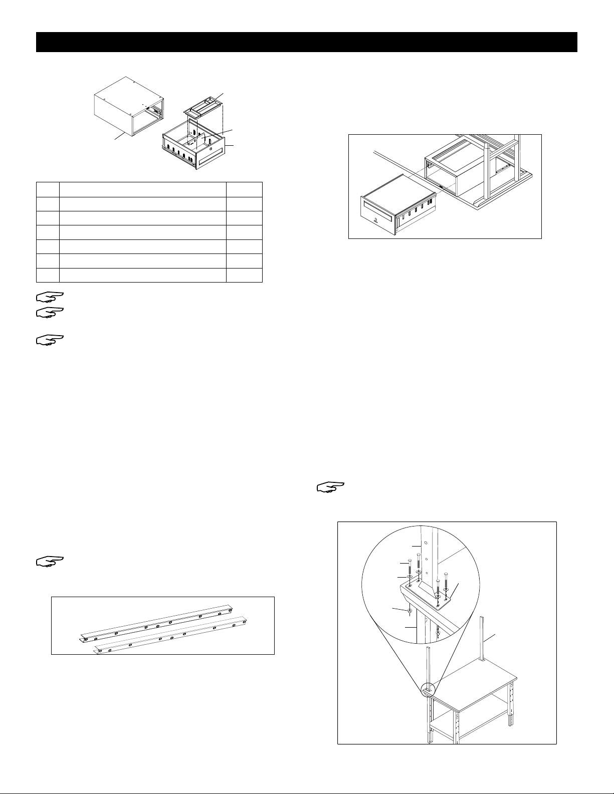
1. Insert adjustable feet (1) into legs (2) and slide into
place at desired height.
NOTE: If desired, insert locking tabs through
legs and adjustable feet to lock feet into place.
2. Place legs (2) in upright position. Legs should be
placed approximately 53" apart for 60" workstations
and 65" apart for 72" workstations. The 96"
workstations
use three legs that should be placed 45" apart.
3. Attach stringer (3) to legs using center holes in back
of legs. Fasten using eight 1/4-20 x 5/8" bolts, lock
washers and nuts (12 bolts, lock washers and nuts
for the 96" workstation), but do not fully tighten.
(See Figure 1)
4. Place lower shelf (4) across braces of legs. Attach
lower shelf using eight 1/4-20 x 5/8" bolts and nuts
(16 bolts and nuts for the 96" workstation). Now, fully
fasten hardware placed in step 3. (See Figure 2)
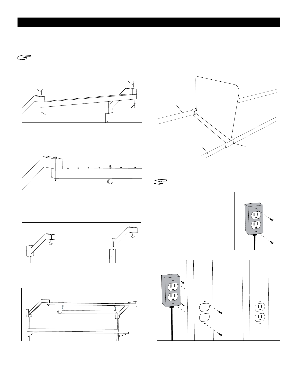
5. To attach tabletop (5) to frame assembly, place
tabletop on a smooth, non-marring surface with top
side facing down.
6. Rotate assembled frame upside down and line up
with pre-drilled pilot holes on the bottom side of
tabletop.
WOOD, LAMINATE, ESD, STAINLESS STEEL
TOP ASSEMBLY
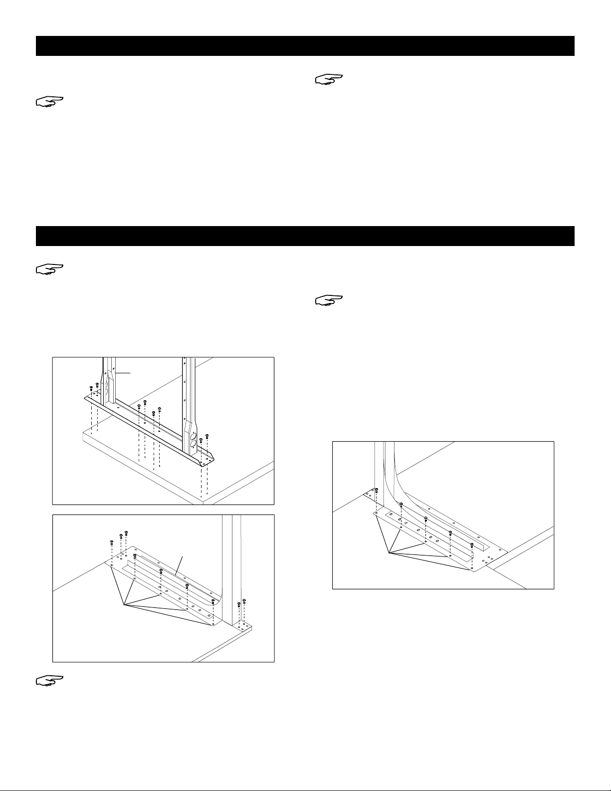
1. Using six wood screws, attach leg to underside of
tabletop (5) through pre-drilled pilot holes. Only
insert screws into the front and center pre-drilled
pilot holes. Holes in the back should not be used at
this time. (See Figure 3)
FOR 96" WORKSTATIONS ONLY: For the center leg only,
insert two additional wood screws into the pre-drilled
pilot holes at the back of the table.
2. Using a 1/4" drill bit, drill four holes all the way through
tabletop in the
pre-drilled pilot
hole locations shown
in Figure 3. They should line up with the holes in the
back of the leg. (See Figure 4)
NOTE:
Use cobalt drill bit supplied with uprights
for stainless steel tops. This bit is specifically
designed to drill through stainless steel material.
NOTE: These holes are drilled to allow mounting
of uprights in later steps.
FOR 96" WORKSTATIONS ONLY: Step 2 only applies to
the two ends of the table. The center leg is already fully
assembled.
3. Repeat steps 1 and 2 with other leg(s).
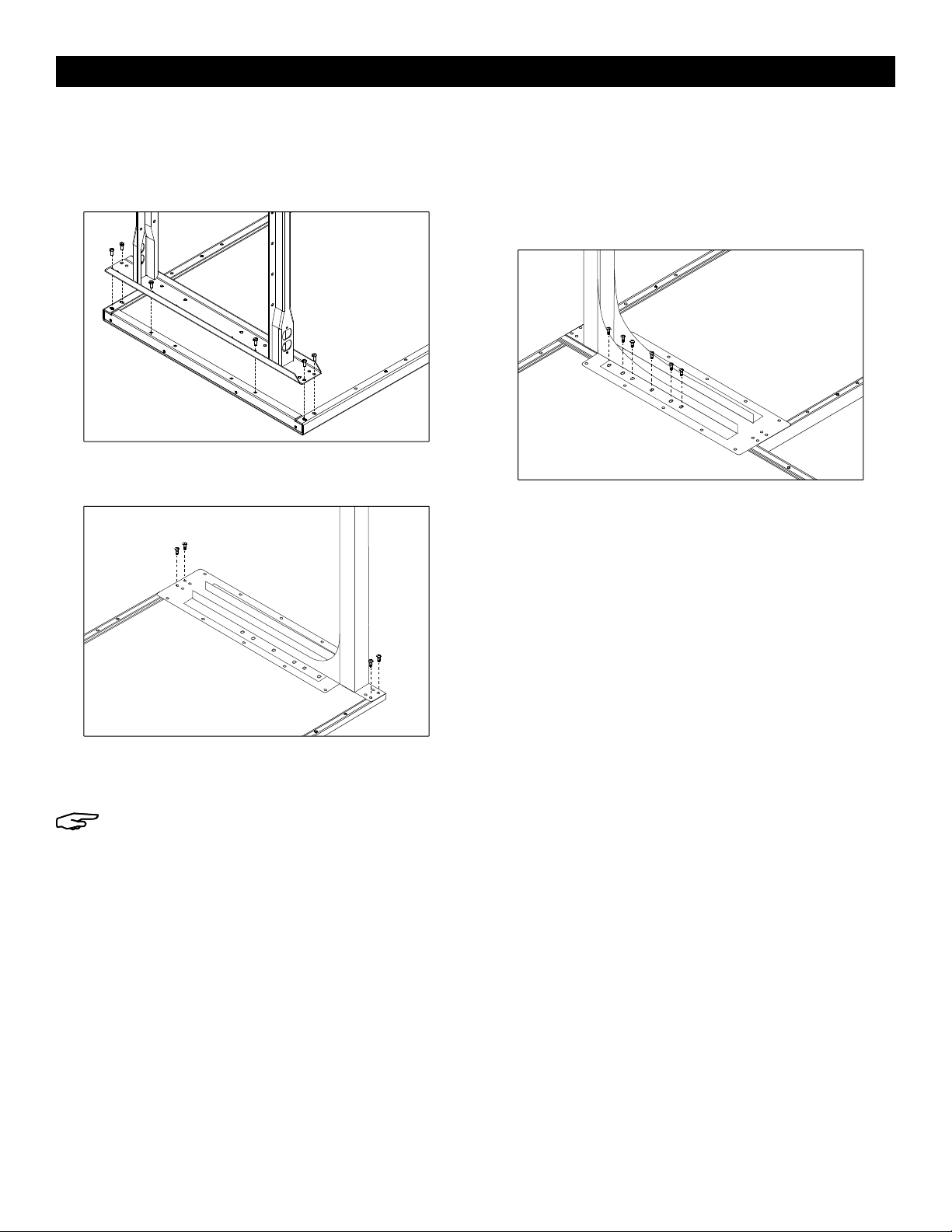
STEEL TOP ASSEMBLY
1. Align leg holes to end of tabletop. Secure with
six 1/4-20 x 5/8" bolts per leg. Threaded inserts are
provided on each tabletop end. (See Figure 5)
FOR 96" WORKSTATIONS ONLY: For the center leg only,
align leg with two holes in center of tabletop on each
end and secure with four 1/4-20 x 5/8" bolts, 1/4-20
nuts and lock washer.
Figure 4
Back
ASSEMBLY
Figure 5 Front
Tabletop
Figure 3
Do Not Insert
Screws
Wood
Screw
Front
Tabletop
Figure 1
Figure 2

PAGE 4 OF 38 1021 IH-5759
DRAWER ASSEMBLY
#DESCRIPTION QTY.
1Drawer 1
2Drawer Housing 1
3Divider 1
4Plastic Tray 1
Keys (Not Shown) 2
Hardware packet (Not Shown) 1
NOTE: Drawer comes pre-assembled.
NOTE: The drawer and suspension have a 70 lb.
weight capacity.
NOTE: Mount drawer on opposite side of
L-Shaped Workstation.
ATTACHING TO NON-STEEL TOP
1. To free drawer (1) from housing (2), fully extend the
drawer from the housing. Flip one plastic tab on the
sliding rails up and the second plastic tab on the
sliding rails down.
2. Using housing as template, mark location of four
holes for wood screws onto underside of tabletop.
(Recommendation: 1/2" offset from front of
tabletop
).
3. Using 5/32" drill bit, drill holes into tabletop, drilling
about 1/2" to 3/4" deep.
4. Secure housing to underside of top, using four
#14-3/4" hex head slotted wood screws.
5. Insert drawer into housing.
ATTACHING TO STEEL TOP
NOTE: Mounting channels are included with
the steel top. (See Figure 6) Channels may
extend past the drawer assembly.
1. On the underside of the table, slide mounting
channels front to back into table flanges. When
channels are aligned, mounting holes should be
approximately 14½" apart. Secure each channel
with two 1/4-20 x 5/8" bolts. (See Figure 7)
2. To free drawer (1) from housing (2), fully extend the
drawer from the housing. Flip one plastic tab on the
sliding rails up and the second plastic tab on the
sliding rails down.
3. Attach the drawer assembly to the mounting
channels using four 1/4-20 x 1/2" bolts. (See Figure 7)
4. Close the drawer.
ATTACHING MULTIPLE DRAWER UNITS
1. To free drawer (1) from housing (2), fully extend the
drawer from the housing. Flip one plastic tab on the
sliding rails up and the second plastic tab on the
sliding rails down.
2. Bolt housing together with four 1/4-20 bolts and nuts.
3. Insert drawer into housing.
UPRIGHT ASSEMBLY
1. Carefully set table upright and recheck all nuts, bolts
and screws for tightness.
2. Position upright (6) on back corner of the tabletop.
The mounting plate should be positioned directly
over the previously drilled holes. Fasten four 2⁄"
bolts and washers through uprights, tabletop and
legs using 10 mm wrench. Secure with flange nuts
on underside of table. (See Figure 8)
NOTE: Steel tops already come with drilled
holes through top.
3. Repeat with other upright. (See Figure 8)
UPRIGHT AND DRAWER ASSEMBLY
Figure 7
Figure 6
Mounting Channels
Figure 8
Upright
Flange
Nut
Mounting
Plate
Upright
Leg
Washer
2⁄" Bolt
1
3
4
2

PAGE 5 OF 38 1021 IH-5759
NOTE: See page 6 for steel top assembly.
L-EXTENSION
1. Using 17 wood screws, attach L-leg (14) and leg (2)
to the underside of 48" top (12) through pre-drilled
holes. (See Figures 9 and 10)
NOTE: For L-Extension and L-Table, five holes
on long end of L-leg will not be pre-drilled. If
desired, pilot holes can be created using a drill
and 3/16" drill bit. Hole should be no deeper
than 3/4".
2. Set bench assembly upright and recheck all nuts,
bolts, and screws for tightness.
NOTE: Do not lean on table. You may need to
prop up corner without leg until table is fully
assembled.
L-TABLE
1. Slide L-extension underneath base table on right or
left hand side. Make sure that table corners align
perfectly. (See Figure 11)
2. Using five wood screws, attach L-leg (14) to
underside of base table top (5). (See Figure 11)
L-EXTENSION
NOTE: For steps 1-3, refer to diagram on page 1.
1. Insert adjustable feet (1) into leg (2) and L-leg (14)
and slide into place at desired height. Insert locking
tabs if desired.
2. Leave legs upside down and space 41" apart.
3. Attach 48" stringer (11) to table legs using center
four holes in back legs. Fasten with eight bolts, lock
washers and nuts.
NOTE: Attach L-leg (14) to left side of stringer for
right side L-table configuration. Attach to right
side of stringer for left side configuration.
4. Place 48" tabletop (12) on a smooth, non-marring
surface with top side facing down.
5. Align assembled frame with the pre-drilled holes on
the bottom side of the top.
NON-STEEL TOP ASSEMBLY
L-SHAPED WORKSTATION ASSEMBLY
Not
pre-drilled
Fig ure 11
Figure 10
Not
pre-drilled
L-Leg
Figure 9
Leg
Front

PAGE 6 OF 38 1021 IH-5759
L-EXTENSION
1. Align leg holes to end of tabletop. Secure leg (2)
with six 1/4-20 x 5/8"bolts. Threaded inserts are
provided. (See Figure 12)
2. Secure L-leg (14) with four 1/4-20 x 5/8" bolts.
Threaded inserts are provided. (See Figure 13)
3. Set bench assembly upright and recheck all nuts,
bolts and screws for tightness.
NOTE: Do not lean on table. You may need to
prop up corner without leg until table is fully
assembled.
L-TABLE
1. Slide L-extension underneath base table on right or
left hand side. Make sure that table corners align
and that the six bolt locations closest to the center
of the leg align with the holes on the edge of the
base tabletop. (See Figure 14)
2. Attach L-leg (14) to underside of base table top (5)
with six nuts, bolts and lock washers.
STEEL TOP ASSEMBLY
Figure 12
Figure 13
Figure 14

PAGE 7 OF 38 1021 IH-5759
BIN RAIL ASSEMBLY
1. Line up bin rail (1) with uprights at desired height.
2. Secure to uprights with four 1⁄" bolts and flange
nuts. (See Figure 15)
SHELF ASSEMBLY
1. Line up shelf brackets (2) with uprights at desired height.
2. Secure to uprights with four 1⁄" bolts and flange
nuts. (See Figure 16)
OPTIONAL ACCESSORIES
2
6
7
1
3520
18, 19
17
14
15
9
12
13
10
11
8
4
16
#DESCRIPTION QTY.
1Bin Rail 1
2 Shelf Bracket 2
3Shelf 1
4Pegboard Panel 2
5Louvered Panel 1
6Panel Mounting Bar 2
7 Panel Bracket 6
8Cabinet 1
9 LED Shop Light 1
10 Light Bracket 2
11 Light Steel Beam 1 ▲
12 "S" Hooks *
13 Shelf Divider *
14 Leg Outlet *
15 Tabletop Power Strip 1
16 Monitor Arm 1
17 Fan 1
18 6" Fan Mounting Bracket 1
19 10" Fan Mounting Bracket 1
20 Fan Upright Mounting Bracket 1
* Quantity varies according to accessories purchased.
▲48" Light Kit does not include steel beam.
CUSTOMIZE YOUR WORKSTATION
NOTE: The following products are optional accessories.
Mounting hardware is included with each accessory.
Figure 15
Figure 16
Flange
Nut
Bin Rail
Upright
Bolt
1⁄"
Bolt Shelf Bracket
Flange Nut
Upright

PAGE 8 OF 38 1021 IH-5759
3. Place shelf (3) on brackets. Install to brackets with
four 5/8" bolts and flange nuts. (See Figure 17)
PEGBOARD AND LOUVERED PANEL
ASSEMBLY
1. Position panel mounting bars (6) at desired height
on the uprights. There should be 8 open holes on the
upright between the top and bottom bar to allow for
panel mounting. Secure bars to upright with four 1⁄"
bolts. (See Figure 18)
NOTE: The holes on the face of the mounting
bars should be facing the inside direction.
2. Attach panel brackets (7) to pegboard panel (4) or
louvered panel (5). Line up holes on bracket with the
four holes on the ends of the panels. Attach four 5/8"
bolts and flange nuts on the center holes only.
(See Figure 19)
3. Install panels (4 and/or 5) to the mounting bars (6).
Line up holes on the top and bottom of the panel
with the holes in the bar. Secure using four 1⁄" bolts
and flange nuts. (See Figure 20)
4. Repeat for additional panels. The 48" workstation
holds up to 2 panels, 60" and 72" workstations hold
up to 3 panels, and the 96" workstation holds up to
4 panels.
5. Assembly is complete. (See Figure 21)
OPTIONAL ACCESSORIES CONTINUED
Figure 17
Figure 18
Figure 21
Completed Assembly
5/8" Bolts
Shelf
Flange Nuts
1½"Bolts
Panel Mounting Bars
Figure 19
Panel Bracket
Panel
Figure 20
1½"
Bolt
Flange Nut

PAGE 9 OF 38 1021 IH-5759
CABINET ASSEMBLY
NOTE: The cabinet and suspension have a 70 lb.
weight capacity.
1. Open the cabinet (8) door. Using a 7/16" wrench
and Phillips screwdriver, remove adjustable shelf by
unscrewing four screws.
ATTACHING TO NON-STEEL TOP
1. Using cabinet as a template, mark location of four
holes for wood screws onto underside of tabletop.
(Recommendation: 1/2" offset from front of table top).
2. Using 5/32" drill bit, drill holes into table top, drilling
about 1/2" to 3/4" deep.
3. Secure cabinet to underside of top, using four
#14-3/4" hex slotted wood screws. (See Figure 22)
NOTE: Cabinet can be flipped to have right or
left facing door.
4. Reinstall adjustable shelf and close cabinet door.
ATTACHING TO STEEL TOP
NOTE: Mounting channels are included with the
steel top. (See Figure 23) Channels may extend
past the cabinet assembly
.
1. On the underside of the table, slide mounting
channels front to back into table flanges. When
channels are aligned, mounting holes should be
approximately 14⁄" apart. Secure each channel
with two 14-20 x 5/8" bolts.
2. Attach the cabinet to the mounting channels using
four 14-20 x 1/2" bolts. (See Figure 24)
NOTE: Cabinet door can be flipped to have
right or left facing door.
3. Close the cabinet door and turn the workstation
right side up. Reinstall adjustable shelf.
LIGHT KIT ASSEMBLY
1. Line up light brackets (10) with uprights at desired
height.
2. Secure to uprights with four 2" bolts and flange nuts.
(See Figure 25)
OPTIONAL ACCESSORIES CONTINUED
Figure 22
Figure 25
Figure 24
Figure 23
Mounting Channels
Flange
Nut
Bolt

PAGE 10 OF 38 1021 IH-5759
3. Place light steel beam (11) at desired depth
underneath brackets. Fasten to brackets (10) with
two 4¾" bolts and flange nuts. (See Figure 26)
NOTE: 48" light kit does not include steel beam.
Skip to 4b.
4a. For 60, 72 and 96" Light Kits: Place two "S" hooks (12)
at desired mounting points along the steel beam
and secure with two flange nuts. (See Figure 27)
4b. For 48" Light Kits: Place two "S" hooks (12) at desired
depth underneath bracket. Fasten to brackets (10)
with two flange nuts. (See Figure 28)
5. Attach hanging chains to LED shop light (9) and
mount to "S" hooks. (See Figure 29)
SHELF DIVIDER ASSEMBLY
1. Line up front "C" channel of divider (13) with front
lip of top shelf. Insert divider into front lip at angle.
Once in place, allow divider to drop and magnetize
to back shelf lip. (See Figure 30)
LEG OUTLET ASSEMBLY
NOTE: Mounting hardware comes pre-installed
in outlet.
1. Remove top and bottom
screws from outside facing
oval outlets. (See Figure 31)
2. Insert outlet (14) into
workbench leg cut outs with
the oval outlets facing the
outside of the leg assembly.
Secure to leg assembly with
the two screws removed in
step one. (See Figure 32)
OPTIONAL ACCESSORIES CONTINUED
Figure 31
Figure 32
Figure 30
Back
Shelf Lip
Front "C"
Channel
Front
Shelf Lip
Figure 27
Figure 26
Figure 29
Figure 28
4⁄"
Bolt
4⁄"
Bolt
Flange Nut
Flange Nut

PAGE 11 OF 38 1021 IH-5759
OPTIONAL ACCESSORIES CONTINUED
Figure 37
Allen
Wrench
Large Flat
Washer
Use appropriate bolts for monitor.
Figure 38
Adjust swivel
with Allen
Wrench
±18 0 º -85º ~15º
±18 0 º
±90º
Adjust Tilt with
Allen Wrench
Figure 36 75 x 75 mm or
100 x 100 mm
75 x 75 mm or
100 x 100 mm
Figure 34
Allen Head
Bolts
Small Flat
Washers
Figure 35
Figure 33
TABLETOP POWER STRIP ASSEMBLY
1. Choose desired location for power strip. Place two
supplied mounting clips roughly 32" apart (clip side
up). Using an electric drill, fasten to tabletop with
two supplied wood screws. (See Figure 33)
2. Secure power strip (15) by snapping into the
mounting clips. (See Figure 34)
MONITOR ARM ASSEMBLY
1. Line up monitor arm mounting bracket (16) with
uprights at desired height.
2. Secure to uprights with two M6 x 35 mm or M6 x 50 mm
Allen head bolts, two small flat washers and two hex
nuts using an Allen wrench and 10 mm wrench.
(See Figure 35)
ATTACHING MONITOR
NOTE: Make sure monitor has a VESA hole pattern
of 100 x 100 mm or 75 x 75 mm. (See Figure 36)
NOTE: If monitor is attached to a fixed base,
remove monitor from base.
CAUTION! Be careful not to scratch screen
during installation.
1. Easy-adjust monitor mount includes a built-in
counterweight system for free-range motion. Arm in
mount may need to be adjusted to allow monitor to
stop
at desired position. Attach monitor to plate.
(See Figure 37)
2. To adjust the counterweight, use 5 x 5 Allen wrench
on screw above middle joint. Turn towards "–" if
monitor raises up. Turn towards "+" if monitor lowers.
Adjust until mount can be stopped at desired
position. (See Figure 38)

PAGE 12 OF 38 1021 IH-5759
CABLE MANAGEMENT
1. To remove covers, use a Phillips head screwdriver
to unscrew the two screws securing covers to the
monitor arm. This allows user to slide cables through
covers. Once complete, re-secure the covers to the
monitor arm using the Phillips head screws.
(See Figure 39)
FAN ASSEMBLY
NOTE: Fan comes with 6" and 10" long bracket.
Choose desired bracket based on application.
1. Slot 6" or 10" fan mounting bracket between opening
in fan upright mounting bracket. Align holes of each
bracket and attach using two M6 x 12 mm hex bolts
and two M6 flange nuts. (See Figure 40)
2. Align hole on the opposite end of fan mounting
bracket to the hole on the crescent fan bracket.
Attach using M12 x 20 mm hex bolt, M12 washer,
M12 lock washer and M12 hex nut. (See Figure 41)
3. Align fan assembly with uprights at desired height.
4. Secure to uprights with two M6 x 40 mm hex bolts
and two M6 flange nuts. (See Figure 42)
OPTIONAL ACCESSORIES CONTINUED
Figure 39
Figure 41
Figure 40 Upright Mounting
Bracket
Fan Mounting Bracket
Figure 42
1
-800-295-551
0
uline.com
Take off covers and put cable in.
Insert screw to lock covers.

PAGE 13 OF 38 1021 IH-5759
800-295-5510
uline.mx
ESTACIONES DE TRABAJO
DE ALTA CALIDAD
PARTES
HERRAMIENTAS NECESARIAS
Desarmador
de Cruz
Desarmador
Plano
Llave Allen
(incluída)
Taladro
Eléctrico
Llave de 7/16"
Llave de 3/8"
Llave de 10 mm
Broca de 1/4"
Broca de 5/32"
2
1
6
6
5
48
9
3
2
7
1
1
11
12
2
1
1
1
10
ESTACIONES DE TRABAJO
DE ALTA CALIDAD
Si adquirió una estación de trabajo, utilice
las instrucciones que están empacadas en la
repisa inferior.
Si adquirió una estación de trabajo con
gabinete, utilice las instrucciones que están
empacadas con el armazón del gabinete.
¡PRECAUCIÓN! Algunas partes pueden tener
bordes filosos. Se debe tener cuidado al
manejar las piezas para evitar lesiones. Por
su seguridad, use guantes de trabajo para
ensamblar las partes.
UNIDAD COMPLEMENTARIA
PARA ESTACIÓN DE TRABAJO
EN FORMA DE L

PAGE 14 OF 38 1021 IH-5759
CONTINUACIÓN DE PARTES
Kit de Tornillería
Rondana de Seguridad
(No es para Cubierta
de Acero)
Estación de Trabajo
de Alta Calidad
8 de 60" y 72"
12 de 96"
Estación de Trabajo
en Forma de L
16 de 72 x 78"
20 de 96 x 78"
Tuerca de 1/4-20
(No es para Cubierta
de Acero)
Estación de Trabajo
de Alta Calidad
16 de 60" y 72"
28 de 96"
Estación de Trabajo
en Forma de L
24 de 72 x 78"
36 de 96 x 78"
Pestaña de Bloqueo
Estación de Trabajo
de Alta Calidad
4 de 60" y 72"
6 de 96"
Estación de Trabajo
en Forma de L
7 de 72 x 78"
9 de 96 x 78"
Tuerca de 1/4-20
(Para Cubierta de Acero)
Estación de Trabajo
de Alta Calidad
16 de 60" y 72"
32 de 96"
Estación de Trabajo
en Forma de L
24 de 72 x 78"
40 de 96 x 78"
Perno de 1/4-20 x 5/8"
(No es para Cubierta
de Acero)
Estación de Trabajo
de Alta Calidad
16 de 60" y 72"
28 de 96"
Estación de Trabajo
en Forma de L
24 de 72 x 78"
36 de 96 x 78"
Perno de 1/4-20 x 5/8"
(Para Cubierta de Acero)
Estación de Trabajo
de Alta Calidad
26 de 60" y 72"
42 de 96"
Estación de Trabajo
en Forma de L
44 de 72 x 78"
56 de 96 x 78"
Tuerca con Reborde
Estación de Trabajo
de Alta Calidad
8 de 60" y 72"
8 de 96"
Estación de Trabajo
en Forma de L
8 de 72 x 78"
8 de 96 x 78"
Perno de 2¾"
Estación de Trabajo
de Alta Calidad
8 de 60" y 72"
8 de 96"
Estación de Trabajo
en Forma de L
8 de 72 x 78"
8 de 96 x 78"
Rondana
Estación de Trabajo
de Alta Calidad
8 de 60" y 72"
8 de 96"
Estación de Trabajo
en Forma de L
8 de 72 x 78"
8 de 96 x 78"
Rondana de Seguridad
(Para Cubierta de Acero)
Estación de Trabajo
de Alta Calidad
8 de 60" y 72"
16 de 96"
Estación de Trabajo
en Forma de L
16 de 72 x 78"
24 de 96 x 78"
Tornillo para Madera
#14-3/4"
(No es para Cubierta
de Acero)
Estación de Trabajo
de Alta Calidad
16 de 60" y 72"
24 de 96"
Estación de Trabajo
en Forma de L
38 de 72 x 78"
46 de 96 x 78"
ESTACIÓN DE TRABAJO DE ALTA CALIDAD
#DESCRIPCIÓN CANT. PARA
60" Y 72" CANT. PARA
96"
1Pata Ajustable 4 6
2Pata 2 3
3Larguero 1 2
4 Repisa Completa Inferior 1 2
5 Cubierta de la Mesa 1 1
6Poste** 2 2
7Cajón 1 1
8Barra de Instalación para
Panel* 2 2
9Soporte para Panel* 6 8
* Para utilizar con paneles opcionales de rejillas y tablero. Vea la página 21.
** Cuando adquiere la cubierta de acero inoxidable, se incluye la broca
de cobalto con los postes.
ESTACIÓN DE TRABAJO EN FORMA DE L
#DESCRIPCIÓN CANT.
72 x78"
CANT.
96 x78"
1Pata Ajustable 7 9
2Pata 3 4
3Larguero 1 1
4 Repisa Media Inferior 1 1
5 Cubierta de la Mesa 1 1
6Poste 2 2
7Cajón 1 1
8Barra de Montaje para
Panel* 2 2
9Soporte para Panel* 6 8
10 Larguero de 48" 1 1
11 Cubierta de 48" 1 1
12 Pata en Forma de L 1 1

PAGE 15 OF 38 1021 IH-5759
ENSAMBLE DE LAS PATAS Y EL ARMAZÓN
1. Inserte las patas ajustables (1) en las patas (2) y
deslícelas hasta colocarlas en su lugar a la altura
deseada.
NOTA: Si lo desea, inserte las pestañas de
bloqueo a través de las patas y las patas
ajustables para fijar las patas en su lugar.
2. Coloque las patas (2) en posición vertical. Las
patas deben colocarse con una separación de
aproximadamente 53" para estaciones de trabajo
de 60" y de 65" para estaciones de trabajo de 72".
Las estaciones de trabajo de 96" requieren tres
patas que deben colocarse con una separación
de 45".
3. Fije el larguero (3) a las patas de la mesa usando
los orificios centrales de las patas posteriores.
Fije usando ocho pernos de 1/4-20 x 5/8", rondanas
de seguridad y tuercas [12 pernos, rondanas de
seguridad y tuercas para la estación de trabajo
de 96"), pero no los apriete por completo.
(Vea Diagrama 1)
4. Coloque la repisa inferior (4) cruzando los
travesaños de los postes. Fije la repisa inferior
utilizando ocho tuercas y pernos de 1/4-20 x 5/8"
(16 pernos y tuercas para la estación de trabajo
de 96"). Ahora apriete por completo la tornillería
colocada en el paso 3. (Vea Diagrama 2)
5. Para fijar la cubierta de la mesa (5) al ensamble del
armazón, voltee la cubierta sobre una superficie lisa
y que no raye, con el lado superior hacia abajo.
6. Voltee el armazón ensamblado al revés y alinéelo
con los orificios de guía preperforados ubicados en
la parte inferior de la cubierta de la mesa.
ENSAMBLE DE LA CUBIERTA DE MADERA,
PLÁSTICO LAMINADO, ESD Y ACERO
INOXIDABLE
1. Usando seis tornillos para madera, fije las patas
a la parte inferior de la cubierta de la mesa (5) a
través de los orificios de guía preperforados. Inserte
los tornillos únicamente en los orificios de guía
preperforados delanteros y centrales. Los orificios
de la parte posterior no deben usarse en este
momento. (Vea Diagrama 3)
SOLO PARA ESTACIONES DE TRABAJO DE 96": Solo es
para la pata central, inserte dos tornillos para madera
adicionales en los orificios de guía preperforados
ubicados en la parte posterior de la mesa.
2. Con una broca de 1/4", perfore cuatro orificios de
que atraviesen por completo la cubierta de la
mesa en las ubicaciones de los orificios guía
preperforados que se muestran en el Diagrama 3.
Se deben alinear con los orificios en la parte
posterior de la pata. (Vea Diagrama 4)
NOTA: Utilice la broca de cobalto que se
suministra con los postes para las cubiertas de
acero inoxidable. Esta broca está diseñada
específicamente para hacer perforaciones en
material de acero inoxidable.
NOTA: Estos orificios se perforan para permitir
el montaje de los postes más adelante.
SOLO PARA ESTACIONES DE TRABAJO DE 96": El paso 2
solo aplica para los dos extremos de la mesa. La pata
central ya está completamente ensamblada.
3. Repita los pasos 1 y 2 con la(s) otra(s) pata(s).
ENSAMBLE
Parte Posterior
Diagrama 4
Diagrama 3
No Inserte
Tornillos
Tornillo
para Madera
Cubierta
de la Mesa
Parte Frontal
Diagrama 1
Diagrama 2

PAGE 16 OF 38 1021 IH-5759
ENSAMBLE DE LA CUBIERTA DE ACERO
1. Alinee los orificios de las patas en el extremo de
la cubierta. Asegure cada pata con seis pernos
de 1/4-20 x 5/8". Enrosque los insertos que se
proporcionan en cada extremo de la cubierta.
(Vea Diagrama 5)
SOLO PARA ESTACIONES DE TRABAJO DE 96": Solo para
la pata central, alinee la pata con los dos orificios en
el centro de la cubierta en cada extremo y asegure
con cuatro pernos de 1/4-20 x 5/8", tuercas de 1/4-20 y
rondanas de seguridad.
ENSAMBLE DE POSTES Y CAJÓN
CONTINUACIÓN DE ENSAMBLE
Diagrama 6
Canales de Montaje
1
3
4
2
Diagrama 5
Parte
Frontal
Cubierta
de la Mesa
ENSAMBLE DEL CAJÓN
#DESCRIPCIÓN CANT.
1Cajón 1
2Carcaza del Cajón 1
3Divisor 1
4 Bandeja de Plástico 1
Llaves (No Se Muestran) 2
Paquete de Tornillería (No Se Muestra) 1
NOTA: El cajón viene preensamblado.
NOTA: El cajón y la suspensión tienen una
capacidad de peso de 31.8 kg (70 lbs.).
NOTA: Instale el cajón en el lado opuesto de la
Estación de Trabajo en Forma de L.
FIJAR A LA CUBIERTA (EXCEPTO LA DE ACERO)
1. Para liberar el cajón (1) de la carcaza (2), extienda
por completo el cajón de la carcaza. Levante una
de las pestañas de plástico y baje la otra de los
rieles deslizantes.
2. Usando la carcaza a modo de plantilla, marque
la ubicación de cuatro orificios para tornillos
para madera en la parte inferior de la superficie
de la mesa. (Recomendación: a 1.3 cm (1/2") de
distancia de la parte frontal de la carcaza).
3. Usando una broca de 5/32", perfore los orificios
en la superficie de la mesa con una profundidad
aproximada entre 1.3 cm (1/2") y 1.9 cm (3/4").
4. Fije la carcaza a la parte inferior de la superficie
usando cuatro tornillos para madera ranurados de
cabeza hexagonal de #14-3/4".
5. Inserte el cajón en la cubierta.
FIJAR A LA CUBIERTA DE ACERO
NOTA: Los canales de montaje vienen incluidos
con la mesa de acero. (Vea Diagrama 6)
Los canales pueden extenderse más allá del
ensamble del cajón.

PAGE 17 OF 38 1021 IH-5759
Diagrama 8
Perno
de 2⁄"
Poste
Poste
Pata
Tuerca
con
Reborde
Placa de
Instalación
CONTINUACIÓN DE ENSAMBLE DE POSTES Y CAJÓN
ENSAMBLE DE LA ESTACIÓN DE TRABAJO EN FORMA DE L
1. En la parte inferior de la mesa, deslice los canales
de montaje del frente hacia atrás dentro de los
bordes de la mesa. Cuando los canales estén
alineados, los orificios de montaje deben quedar
aproximadamente a 36.8 cm (14½") de distancia.
Asegure cada canal con dos pernos de
1/4-20 x 5/8". (Vea Diagrama 7)
2. Para liberar el cajón (1) de la cubierta (2), extienda
por completo el cajón de la cubierta. Levante una
de las pestañas de plástico y baje la otra de los
rieles deslizantes.
3. Fije el ensamble del cajón a los canales de
montaje utilizando cuatro pernos de 1/4-20 x 1/2".
(Vea Diagrama 7)
4. Cierre el cajón.
FIJAR UNIDADES CON MÚLTIPLES CAJONES
1. Para liberar el cajón (1) de la carcaza (2), extienda
por completo el cajón de la carcaza. Levante una
de las pestañas de plástico y baje la otra de los
rieles deslizantes.
2. Fije la carcaza con cuatro pernos y tuercas de 1/4-20.
3. Inserte el cajón en la carcaza.
INSTALACIÓN DE LOS POSTES
1. Cuidadosamente, coloque la mesa en posición
vertical y verifique que haya apretado bien todas
las tuercas, los pernos y los tornillos.
2. Coloque el poste (6) en la esquina posterior de
la cubierta de la mesa. La placa de instalación
debe colocarse directamente sobre los orificios
perforados anteriormente. Fije cuatro pernos de
2⁄" y rondanas a través de los postes, la cubierta
de la mesa y las patas usando una llave de 10 mm.
Asegúrelos a la parte inferior de la mesa usando
tuercas con reborde. (Vea Diagrama 8)
NOTA: Las cubiertas de acero ya vienen con
los orificios perforados a través de la cubierta.
3. Repita con el otro poste. (Vea Diagrama 8)
Diagrama 7
EXTENSIÓN EN L
NOTA: Para los pasos 1-3, consulte el diagrama
en la página 13.
1. Inserte la base ajustable (1) en la pata (2) y la pata
en L (14) y deslice a la altura deseada. Inserte las
pestañas de bloqueo si lo desea.
2. Deje las patas hacia abajo y el espacio a 41" de
distancia.
3. Fije el larguero de 48" (11) a las patas de la mesa
utilizando cuatro orificios centrales en las patas
posteriores. Sujete con ocho pernos, rondanas de
seguridad y tuercas.
NOTA: Fije la pata en L (14) en el lado izquierdo
del larguero para la configuración derecha de
la mesa en L. Fije al lado derecho del larguero
para la configuración del lado izquierdo.
4. Coloque la cubierta de 48" (12) sobre una superficie
lisa que no deje marcas, con el lado superior hacia
abajo.
5. Alinee el armazón ensamblado con los orificios
preperforados de la parte inferior de la cubierta.
Rondana

PAGE 18 OF 38 1021 IH-5759
NOTA: Vea la página 19 para el ensamble de
la cubierta de acero.
EXTENSIÓN EN L
1. Utilizando 17 tornillos para madera, fije la pata en
L (14) y la pata (2) en la parte inferior de la cubierta
de 48" (12) a través de los orificios preperforados.
(Vea Diagramas 9 y 10)
NOTA: Para la Extensión en L y la Mesa en L
no se harán perforaciones previas de cinco
orificios en el extremo de la pata en L. Si lo
desea, puede hacer los orificios de guía con
un taladro y una broca de 3/16". El orificio no
debe ser más profundo que 3/4".
2. Coloque la mesa de forma vertical y revise
nuevamente que todos los tornillos, pernos y
tuercas estén apretados.
NOTA: No se recargue en la mesa. Es posible
que necesite sostener la esquina sin la pata
hasta que la mesa esté armada por completo.
MESA EN L
1. Deslice la Extensión en L debajo de la base de la
mesa en el lado derecho o izquierdo. Asegúrese de
que las esquinas se alineen a la perfección.
(Vea Diagrama 11)
2. Utilizando cinco tornillos para madera, fije la pata
en L (14) debajo de la cubierta de la base de la
mesa (5). (Vea Diagrama 11)
ENSAMBLE DE CUBIERTA QUE NO SEA DE ACERO
No están
preperforados
Diagrama 11
Diagrama 10
No están
preperforados
Pata en L
Diagrama 9
Pata
Parte Frontal

PAGE 19 OF 38 1021 IH-5759
EXTENSIÓN EN L
1. Alinee los orificios de las patas al extremo de la
cubierta. Asegure la pata (2) con seis pernos de
1/4-20 x 5/8". Insertos roscados incluidos.
(Vea Diagrama 12)
2. Asegure la pata en L (6) con cuatro pernos de
1/4"-20 x 5/8". Insertos roscados incluidos.
(Vea Diagrama 13)
3. Coloque la mesa de forma vertical y revise
nuevamente que todos los tornillos, pernos y tuercas
estén apretados.
NOTA: No se recargue en la mesa. Es posible
que necesite sostener la esquina sin la pata
hasta que la mesa esté armada por completo.
MESA EN L
1. Deslice la Extensión en L debajo de la base de
la mesa del lado izquierdo o derecho. Asegúrese
de que las esquinas de la mesa estén alineadas y
que las seis ubicaciones de los pernos estén más
cercanas al centro de la alineación de la pata con
los orificios del borde de la base de la cubierta.
(Vea Diagrama 14)
2. Fije la pata en L (6) debajo de la cubierta de
la base de mesa (5) con seis pernos, tuercas y
rondanas de seguridad.
ENSAMBLE DE LA CUBIERTA DE ACERO
Diagrama 13
Diagrama 14
Diagrama 12

PAGE 20 OF 38 1021 IH-5759
ACCESORIOS OPCIONALES
2
6
7
1
3520
18, 19
17
14
15
9
12
13
10
11
8
4
16
#DESCRIPCIÓN CANT.
1 Riel para Gavetas 1
2 Soporte de Repisa 2
3 Repisa 1
4Tablero Perforado 2
5 Panel con Rejillas 1
6Barra para Instalar el Panel 2
7 Soporte de Panel 6
8Gabinete 1
9Lámpara LED para Taller 1
10 Soporte para Lámpara 2
11 Viga de Acero Ligera 1 ▲
12 Ganchos en "S" *
13 Divisores de Repisa *
14 Toma de Corriente en la Pata *
15 Multicontacto de Mostrador 1
16 Brazo para Monitor 1
17 Ventilador 1
18 Soporte de Instalación para Ventilador de 6" 1
19 Soporte de Instalación para Ventilador de 10" 1
20 Soporte del Poste de Instalación para Ventilador 1
* Las cantidades varían de acuerdo con los accesorios que adquiera.
▲El Kit de Lámpara de 48" no incluye la viga de acero.
PERSONALICE SU ESTACIÓN DE TRABAJO
NOTA: Los productos que se muestran a continuación son accesorios opcionales.
Se incluye la tornillería de instalación con cada accesorio.
ENSAMBLE DEL RIEL PARA GAVETAS
1. Alinee el riel para gavetas (1) con los postes a la
altura deseada.
2. Fíjelo a los postes usando cuatro pernos de 1⁄" y
tuercas con reborde. (Vea Diagrama 15)
ENSAMBLE DE LA REPISA
1. Alinee los soportes de repisa (2) con los postes a la
altura deseada.
2. Fíjelos a los postes usando cuatro pernos de 1⁄" y
tuercas con reborde. (Vea Diagrama 16)
Diagrama 16
Diagrama 15
Tuerca con
Reborde
Poste
Riel para Gavetas
Perno
Perno
de 1½" Soporte de Repisa
Tuerca con
Reborde
Poste
This manual suits for next models
9
Table of contents
Languages:
Other U-Line Desktop manuals