intermovtive PRPC501-A User manual

www.intermotive.net
products@intermotive.net
PRPC501-A-090314-INS
Inter otive Inc.
13395 New Airport Rd.
Auburn, CA 95602
Phone: (530)-823-1048
Fax: (530)-823-1516
Page 1 of 13
An ISO 9001:2008 Registered Company
PRPC501-A
Programmable Relay Power Center
See PRPC Programming Utility software for latest list of supported vehi les
2009-2014 Ford E-Series and F-Series
Contact Intermotive for additional applications
Introdu tion
The Programmable Relay Power Center provides access to a broad
range of vehicle data such as PH, RP , Park Brake, Service Brake,
temperatures, transmission range, accelerator pedal, doors, lights,
door locks, ABS, IL, etc. Specific data is vehicle dependent, and by
running the PRPC Programming Utility software (free download from
www.intermotive.net), available information on a particular chassis can easily be determined.
The PRPC provides 8 configurable relay outputs, eight configurable low current outputs
(1/2A ax), and six configurable beepers. The Programmer allows logical combinations
(AND, OR, =, >, <) of various vehicle data to control an output. For example, one output can be
programmed to go active when ECT>230 OR TFT>250 AND RP >300 (any numeric values can
be used). This could drive a high temperature dash indicator. Another output could be
programmed to drive a warning buzzer/lamp when the vehicle speed exceeds some limit, such as
70mph. Electric doors can be disabled unless certain safety conditions are met and so on. There
are also ten general purpose inputs, one analog input, and one dedicated ignition input that can
be used as part of the programmable logic.
PRPC Programming Ulity Instrucons
(Used for configuring the programmable outputs, beepers and inputs)
Requirements:
• Java Runtime Environment (v1.7.0 or later) must be installed on your computer prior to running
this utility. ost PC’s already have Java installed. The most recent version can be obtained for
free at http://java.com/en/download/manual.jsp.
• The PRPC Programming Utility. This is a free Intermotive software program that will need to
be loaded on your PC. The files are available from the download page at
www.intermotive.net. It is recommended that an “Inter otive” folder be created to store the
files.
• USB to Serial cable (part# s-h37a1) is included in the a-IPU kit and is a one-time purchase.
This kit is required for all programming and is recommended to be kept in a central location.
Once PRPC Programming Utility has been run and the specific configuration has been created, it
can be downloaded onto the PRPC501-A module(s) with the Programming Utility.

Computer Installation:
1. Ensure the proper driver is installed for the USB to Serial download cable. This driver
can be found at: http://www.ftdi hip. om/Drivers/VCP.htm
2. To install the programming utility, unzip the PRPC Programming Utility folder to your
local hard drive.
3. Create a shortcut on the desktop if necessary, but do not
separate the PRPC Programming Utility.exe file from the
rxtxSerial.dll file!
4. Plug in the USB cable (Part# s-h37a1) prior to starting the
application.
5. Double click the PRPC Programming Utility.exe file to launch.
6. This screen will come up.
If the program does not launch, close all applications and reinstall
the Java Runtime Environment and the PRPC Programming Utility.
Setting the PRPC Programming Utility Pin Configurations:
To view a video on tips for configuring the module, go to www.Intermotive.net
1. Under the “Home” tab select the model year, manufacturer,
model, and engine size of the vehicle the PRPC will be in-
stalled in.
2. Click the “Create Configuration” button.
3. This screen will come up.
4. Configure as desired. See the following page for more infor-
mation. Press the Enter button after each entry.
Note: CTO can only be programmed on LCO5 (J4-5).
2.2 Hz per PH can only be programmed on LCO6
(J4-6).
5. Select “Save Configuration” under the “File” tab.
6. Enter a configuration name ( ax. 16 characters) and click “OK”.
7. Review the configuration summary and click “Save Configuration”.
8. Enter a filename and choose a location that will be easy to locate.
9. Under the “File” menu, select “Save Configuration Summary”.
10. Double click the .ims file previously configured.
11. Enter Company Name, phone number, and notes and click the ‘OK’ button. Note: Enter
the vehi le model year, model, and engine in the notes se tion.
12. Enter a file name and click the ‘Save’ button.
13. Click the ‘Open File’ button.
14. Right click on summary and select ‘Print’.
15. Cut the printed label and place it in the bag attached to the PRPC module.
Inter otive Inc.
13395 New Airport Rd.
Auburn, CA 95602
Phone: (530)-823-1048
Fax: (530)-823-1516
Page 2 of 13
www.intermotive.net
products@intermotive.net
PRPC501-A-090314-INS
Inter otive Inc.
13395 New Airport Rd.
Auburn, CA 95602
Phone: (530)-823-1048
Fax: (530)-823-1516
Page 3 of 13
www.intermotive.net
products@intermotive.net
PRPC501-A-090314-INS
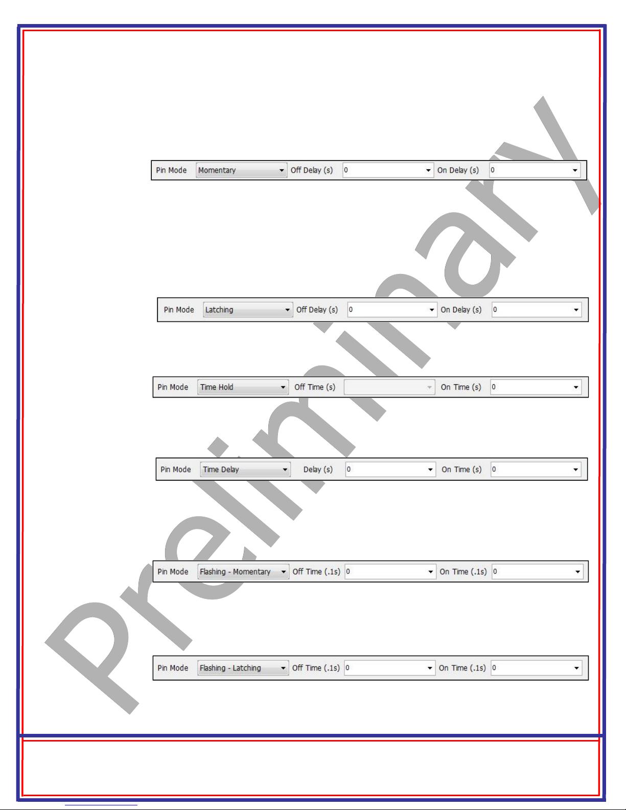
Setting Pin Mode— PRPC Appli ation Software
Momentary: Output follows condition set but with a turn on delay, and a turn off delay. Setting ‘On
Delay’ and ‘Off Delay’ to zero causes the output pin to simply “follow” the condition set being true (ON)
and false (OFF).
Lat hing: This mode will latch an output pin ON, starting ‘On Delay’ seconds after the conditions are
met, and will keep it ON even after the conditions are no longer true. It will then latch the output OFF,
following ‘Off Delay’ seconds after the conditions are met again. It can be thought of as toggle
On/toggle Off. The simplest use would be when using a momentary button as the only input condition
and setting the Delays to zero. Thus a load could be turned on by pushing a momentary button, and
turned back off by pushing the button a second time.
Time Hold: The output pin goes ON after the conditions become true, and stays ON for the selected
‘On Time’, regardless of the conditions. Off Time is Not Applicable.
Time Delay: Output is turned ON after the selected ‘delay’ time after the conditions are met. It
stays on for selected ‘On time’, regardless of input conditions.
Flashing—Momentary: Used for creating a flashing output. When conditions are met, output flash-
es. When conditions are no longer met, flashing stops. Flashing ON and OFF times (duty cycle) are
controlled by entering the following values.
Flashing - Lat hing: Same as above, except flashing will continue after conditions are no longer
true, and will stop when conditions become true again—toggle ON, toggle OFF. Duty cycle is con-
trolled by the ON and OFF times.

Desktop Programming the PRPC
The Inter otive “a-IPU” kit is sold separately and allows pro-
gramming the PRPC on your desktop. It consists of a 12VDC wall
adapter and download cable and works with the PRPC program-
ming software utility.
Note: Do not have the PRPC Programming Utility opened
until instru ted to do so.
1. Plug the odule Desktop Power/Ground Supply inverter
into a 120V AC power source.
2. Locate the 6-Pin Female connector on the module but
do not connect the AC adapter to the PRPC module
until indicated in the following steps.
3. Plug the phone jack end of the download cable into the
J8 CO port of the PRPC module and the USB end into
your PC.
J8 COMM Port
Loading your previously reated Configuration file into the PRPC:
Open the PRPC Programming Utility. Under the “Home” tab on the PRPC Programming Utility,
choose the CO Port the USB cable is connected to.
Note: This can be determined on Windows XP by right-clicking on ‘ y Computer’ and selecting
‘Properties.’ From this window select the ‘Hardware’ tab and click on ‘Device anager.’ In the De-
vice anager window, expand the ‘Ports’ menu and the download cable will display as ‘USB Serial
Port.’
Click the ‘Open File’ button.
1. Open the PRPC*.ims or configuration file to load on the PRPC501-A module. (This file
must already be loaded on the computer).
2. Click the load button on the computer screen. “Waiting” will come up next to the progress bar.
This means the program is waiting for the power to be plugged into the PRPC module.
3. Plug in the 6 pin connector of the power adapter into the PRPC501-A module. The progress bar
on the computer screen will display status as the configuration loads and takes approximately 2
seconds or less. Configuration is loaded once the screen says “DONE” and programming is
complete.
4. To verify that the correct data was loaded into the module, disconnect the 6 pin connector
from the module and press the ‘Get” button on the screen. Plug in the 6 pin connector and
the information will be displayed.
To program another module with the same configuration file, start with step 2.
Inter otive Inc.
13395 New Airport Rd.
Auburn, CA 95602
Phone: (530)-823-1048
Fax: (530)-823-1516
Page 4 of 13
www.intermotive.net
products@intermotive.net
PRPC501-A-090314-INS

Installation Instru tions
Data Link Harness (6-pin onne tor)
1. Locate the vehicles OBDII Data Link Connector. It will be mounted below the lower
left dash panel.
2. Remove the mounting screws for the OBDII connector. Plug the Red connector
from the PRPC Data Link Harness into the vehicle’s OBDII connector. Ensure the
connection is fully seated and secure with the supplied wire tie.
3. ount the pass-through connector from the PRPC Data Link Harness
in the former location of the vehicle’s OBDII connector.
4. Secure the PRPC Data Link harness so that it does not hang below
the lower dash panel.
NOTE: Do NOT plug the Data Link harness into the 6-pin connector on
the PRPC501-A module. This will be done at a later step.
Dis onne t the battery before pro eeding with the installation.
PRPC501 Module
Find a suitable location to mount the PRPC501 module. Do not mount the module where it will
be exposed to excessive heat. Do not mount the module until all wire harnesses are routed and
secure. The last step of the installation is to mount the module.
Inter otive Inc.
13395 New Airport Rd.
Auburn, CA 95602
Phone: (530)-823-1048
Fax: (530)-823-1516
Page 5 of 13
www.intermotive.net
products@intermotive.net
PRPC501-A-090314-INS
PRPC Power Lug
Connect a 65A fused VBAT source to the 1/4” power bolt. The PRPC is
designed for a maximum cable size of 2 AWG for this power connec-
tion. Installer
must
provide strain relief on cable outside of the PRPC’s
enclosure. It is recommended that the strain relief is within 6” of the
enclosure. The absence of strain relief could result in damage to the
module.
IMPORTANT—READ BEFORE INSTALLATION
It is the installer’s responsibility to route and secure all wiring harnesses where they cannot be
damaged by sharp objects, mechanical moving parts and high heat sources. Failure to do so could
result in damage to the system or vehicle and create possible safety concerns for the operator and
passengers. Avoid placing the module where it could encounter strong magnetic fields from high
current cabling connected to motors, solenoids, etc. Avoid radio frequency energy from antennas
or inverters next to the module. Avoid high voltage spikes in vehicle wiring by always using diode
clamped relays when installing upfitter circuits.

6-Pin PRPC Conne tor Pin-Out Definition
Connector J18 contains 6 of the PRPC’s 11 fused output pins. These 6 fused output pins are
connected to 4 configurable relay outputs. Each relay output is capable of 15 Amps maxi-
mum. Configurable relay output 4 is shared by fuses 4A, 4B, and 4C. When added together
the sum of these three fuses must not exceed 20 Amps. Note that the placement of fuse 3
will determine whether the output is active high or active low. The use of fused outputs 4A,
4B, or 4C is recommended for higher current loads. The PRPC module has an absolute
maximum urrent rating of 65 Amps.
The 6 fused output pins on connector J18 are defined as follows:
• Pin #1 (White wire) Configurable Relay Output 4, Fuse 4C, Active High
• Pin #2 (White wire) Configurable Relay Output 4, Fuse 4B, Active High
• Pin #3 (White wire) Configurable Relay Output 4, Fuse 4A, Active High
• Pin #4 (White wire) Configurable Relay Output 3, Fuse 3,
Fuse Selectable Active High/Low
• Pin #5 (White wire) Configurable Relay Output 2, Fuse 2, Active High
• Pin #6 (White wire) Configurable Relay Output 1, Fuse 1, Active High
Connect the desired outputs to vehicle equipment as needed. Tape up unused leads.
6 Pin Output Ba k of Conne tor
Inter otive Inc.
13395 New Airport Rd.
Auburn, CA 95602
Phone: (530)-823-1048
Fax: (530)-823-1516
Page 6 of 13
www.intermotive.net
products@intermotive.net
PRPC501-A-090314-INS
The default configuration for the relay outputs on J18 are as follows:
• Pin #1 (White wire),
• Pin #2 (White wire),
• Pin #3 (White wire),
• Pin #4 (White wire), Left Turn Signal On
• Pin #5 (White wire), Key On
• Pin #6 (White wire), Low Beams or High Beams
2-Pin PRPC Conne tor
Connector J20 contains the two black ground wires for relay output fuse sensing,
motor reversing, and low true relay outputs. This is not an optional connection. The
wires in this connector must be attached to a good chassis ground for the system to
function properly.
1 2 3 4 5 6
Right Turn Signal On

The default configuration for the relay outputs on J17 are as follows:
• Pin #1 (White wire) IN1 or IN2 Active
• Pin #2 (White wire) IN2 Active
• Pin #3 (White wire) IN1 Active
• Pin #4 (White wire)
• Pin #5 (White wire)
Inter otive Inc.
13395 New Airport Rd.
Auburn, CA 95602
Phone: (530)-823-1048
Fax: (530)-823-1516
Page 7 of 13
www.intermotive.net
products@intermotive.net
PRPC501-A-090314-INS
5-Pin PRPC Conne tor Pin-Out Definition
Connector J17 contains 5 of the PRPC’s 11 fused output pins. These 5 fused output pins are connected
to 4 configurable relay outputs. Each relay output is capable of 15 Amps maximum. Configurable relay
output 5 is shared by fuses 5A and 5B. When added together the sum of these fuses must not exceed
20 Amps. Note that the placement of fuse 6 will determine whether the output is active high or active
low. The use of fused outputs 5A or 5B is recommended for higher current loads. The PRPC module
has an absolute maximum urrent rating 65 Amps.
The 5 fused output pins on connector J17 are defined as follows:
• Pin #1 (White wire) Configurable Relay Output 8, Fuse 8, Active High
• Pin #2 (White wire) Configurable Relay Output 7, Fuse 7, Active High
• Pin #3 (White wire) Configurable Relay Output 6, Fuse 6, Fuse Selectable Active High/Low
• Pin #4 (White wire) Configurable Relay Output 5, Fuse 5B, Active High
• Pin #5 (White wire) Configurable Relay Output 5, Fuse 5A, Active High
Connect the desired outputs to vehicle equipment as needed. Tape up unused leads.
5 Pin Output Ba k of Conne tor
ECT > 230F or TFT > 250F
1 2 3 4 5

8-Pin PRPC Conne tor Pin-Out Definition
Connector J4 contains the PRPC’s 8 low current output pins. Each output is rated at 1/2A and is
intended to drive relay coils or other low current loads. Note that Pin 8 of the eight outputs is ac-
tive low (ground) while the rest are active high (12V). Note: when driving relays, a diode-
prote ted type must be used. InterMotive re ommends DigiKey #PB682-ND Relay.
The 8 outputs are defined as follows:
• Pin #1 (Yellow wire) Configurable Output, Active High
• Pin #2 (White wire) Configurable Output, Active High
• Pin #3 (Brown wire) Configurable Output, Active High
• Pin #4 (Gray wire) Configurable Output, Active High
• Pin #5 (Blue wire) Configurable Output, Active High
• Pin #6 (Green wire) Configurable Output, Active High
• Pin #7 (Orange wire) Configurable Output, Active High
• Pin #8 (Pink wire) Configurable Output, A tive Low*
Connect the desired outputs to vehicle equipment as needed. Tape up
unused leads. When connecting to relays, use relays with appropriate
kick-back suppression, such as Digikey #PB682-ND. Unsuppressed relays
will induce very high voltage spikes throughout modern vehicles sensitive
computer electronics and should not be used, per Ford, G , SAE, etc.
The default configuration for the 8 outputs are as follows:
• Pin #1 (Yellow wire) Trans Range=Reverse - Flashing omentary, 2 seconds On, 2 seconds Off
• Pin #2 (White wire) Transmission = Park
• Pin #3 (Brown wire) Left Turn Signal
• Pin #4 (Gray wire) Right Turn Signal
• Pin #5 (Blue wire) CTO*
• Pin #6 (Green wire) Any Door Open
• Pin #7 (Orange wire) Vehicle Speed > 76
• Pin #8 (Pink wire) Engine Running
*CTO = ((RP /2)*#Cyl) = pulses per minute. E.G. 600rpm = 2400 (8 cylinders)
8 Pin Output Ba k of Conne tor
Inter otive Inc.
13395 New Airport Rd.
Auburn, CA 95602
Phone: (530)-823-1048
Fax: (530)-823-1516
Page 8 of 13
www.intermotive.net
products@intermotive.net
PRPC501-A-090314-INS

12-Pin Input Conne tor Definition
Connector J3 contains the PRPC’s 12 discrete wire inputs. There are 3 configurable active high/
low, 7 active low inputs, 1 analog input, and 1 dedicated ignition input. These inputs have their
own internal pull up/pull down resistors so they can be left floating when not used or not active.
These inputs can be used as part of the programmable logic to configure the output pins.
• Pin #1 - (Yellow/Black stripe) Input 1, Configurable Active high/low
• Pin #2 - (Brown/White stripe) Input 2, Configurable Active high/low
• Pin #3 - (White/Black stripe) Input 3, Configurable Active high/low
• Pin #4 - (Green/White stripe) Input 4, Active low
• Pin #5 - (Gray/Black stripe) Input 5, Active low
• Pin #6 - (Purple/White stripe) Input 6, Active low
• Pin #7 - (Blue/White stripe) Input 7, Active low
• Pin #8 - (Pink/Black stripe) Input 8, Active low
• Pin #9 - (Black/White stripe) Input 9, Active low
• Pin #10 - (Orange/Black stripe) Input 10, Active low
• Pin #11 - (Tan/Black stripe) Input 11, Analog
• Pin #12 - (Red/White stripe) Input 12, Dedicated Ignition
Connect inputs as needed. Tape up unused input wires.
Inter otive Inc.
13395 New Airport Rd.
Auburn, CA 95602
Phone: (530)-823-1048
Fax: (530)-823-1516
Page 9 of 13
www.intermotive.net
products@intermotive.net
PRPC501-A-090314-INS
12 Pin Input
Ba k of Conne tor
Beeper Definition - The PRPC501 has 6 unique beeper logic conditions and sounds.
Default Configuration:
Beeper 1: Low pitch, fast, 10 beeps when VBAT < 11.75V
Beeper 2: High pitch, medium, when ECT > 230F or TFT > 250F
Beeper 3: High pitch, continuous, when any I/O fuse is blown
Beeper 4: edium pitch, medium, when the SB and Gas Pedal are depressed
Beeper 5: edium pitch, medium, when VSS > 0 and PB is On
Beeper 6: High pitch, medium, when VSS > 76

Inter otive Inc.
13395 New Airport Rd.
Auburn, CA 95602
Phone: (530)-823-1048
Fax: (530)-823-1516
Page 10 of 13
www.intermotive.net
products@intermotive.net
PRPC501-A-090314-INS
Initial Installation Power-Up:
The following sequence must be performed prior to mounting the PRPC501-A module. The
initial installation is completed as follows:
1. Ensure the Data Link harness 6 pin connector is NOT connected
to the PRPC501 module.
2. Turn the vehicle key on, engine off
3. Insert the Data Link harness 6 pin connector into the PRPC501
module.
4. The PRPC’s red fuse LEDs will “scroll” if the VIN is not
recognized.
Re onne t the vehi le battery
PRPC501-A Module Mounting
Ensure all the harnesses are properly connected and routed. ount the PRPC501 module as
described on page one. Verify the module is in an area away from any external heat sources
(engine heat, heater ducts, etc.), and secure using screws or double sided tape.

PRPC Post Installation Testing
1. Turn the ignition ON to wake up and initialize the PRPC module.
2. With the conditions met, ensure that all desired outputs are responding correctly per their
programmed condition set (e.g., output 5 goes high when engine is running).
The PRPC is properly installed only if it passes the above tests. If any irregular
operational issues persist, re he k the ondition set onfiguration.
Conta t InterMotive at 530-823-1048 for te hni al assistan e.
Inter otive Inc.
13395 New Airport Rd.
Auburn, CA 95602
Phone: (530)-823-1048
Fax: (530)-823-1516
Page 11 of 13
www.intermotive.net
products@intermotive.net
PRPC501-A-090314-INS
Diagnosti s
Relay Outputs:
Each relay has an associated on-board green LED that indicates when the relay coil is active.
These green LEDs can be thought of as conditions met indicators. In addition each fused
output has an on-board red fuse blown LED. These red LEDs are processor controlled. If the
module is not in diagnostics mode and a blown fuse is detected on a configured output the
associated on-board red LED will illuminate. No fuse sensing is done on outputs that are not
configured to turn on.
Low Current Outputs:
To enter LCO diagnostic mode, momentarily press the red test button on the module (look
for “TEST” on the printed circuit board) ONE time with the ignition on. The on-board yellow
status LED will blink once every second in this diagnostic mode. The on-board red fuse
LED’s will light when a corresponding LCO is active:
Output Trouble Codes:
If there is an issue with one of the PRPC outputs, the red fault LED will flash a three digit
code while in diagnostic mode. A 1-1-1 code means everything is working properly. The
second digit flashed will correspond to the output number and the third digit will indicate the
specific problem.
Fuse LED 1 2 3 4A 4B 4C 5A 5B
LCO # 1 2 3 4 5 6 7 8
J4 Pin # 1 2 3 4 5 6 7 8
1’st Digit (Output Type)
2 - PRPC LCO
3 - PRPC Relay
2’nd Digit (Output Number)
LCO Relay #
3’rd Digit (Specific Problem)
•
2 - Output fault (overcurrent or overvoltage)
•
3 - Invalid data (The data associated with the output is invalid)
•
4 - Data timed out (The data associated with the output has timed
out)
•
5 - Unsupported data (The data associated with the output is
not supported on the current vehicle)

PRPC Operation:
Turning the vehicle ignition ON will wake up and initialize the PRPC501 module. Outputs are
controlled based on the module’s configuration created using the Intermotive PRPC Programming
Utility program.
When the key is turned OFF, the PRPC501 module will go into a low power sleep mode . This may
take up to TEN minutes, and the LED’s on the module will go out once in sleep mode. Other vehicle
activity such as opening doors, inserting key in the ignition, etc. may delay sleep mode.
Inter otive Inc.
13395 New Airport Rd.
Auburn, CA 95602
Phone: (530)-823-1048
Fax: (530)-823-1516
Page 12 of 13
www.intermotive.net
products@intermotive.net
PRPC501-A-090314-INS
Inputs:
To enter Input diagnostic mode, momentarily press the red test button on the module (look
for “TEST” on the printed circuit board) TWO times with the ignition on. The on-board yellow
status LED will blink twice every second in this diagnostic mode. The on-board red fuse LED’s
will light when a corresponding Input is active:
Fuse LED 1 2 3 4A 4B 4C 5A 5B
Input # 1 2 3 4 5 6 7 8
J3 Pin # 1 2 3 4 5 6 7 8
6
9
9
7
10
10
8
12
12
S rolling LED’s:
This may indicate one of the following errors:
•
LED’s scrolling sequentially one at a time indicates that an invalid or incomplete VIN was
captured.
•
LED’s scrolling from the middle outward indicates a configuration error. This can be the result
of configuring the PRPC for one chassis, but installing it in a different chassis.
PCB Temperature Load Shedding:
The PRPC monitors on-board temperature in three different locations. If any one of the readings
exceeds a predetermined temperature threshold the module will shed one relay load every 2
minutes to regulate heat. The outputs where the temperature readings are highest will be shut off
first. If at any time a temperature reading is 5C above the predetermined temperature threshold
the module will shed one relay load every second until all relays are off.
If this sequence is triggered the module will beep 5 times in about 30 seconds at high pitch before
shedding any output.

Submit produ t registration at www.intermotive.net
If the PRPC fails any step in the Post Installation Test, review the installation instructions
and the loaded configuration by running the Graphical User Interface application. If necessary, call
InterMotive te hni al support @ (530) 823-1048.
PRPC501-A-090314-CAD
Table of contents


