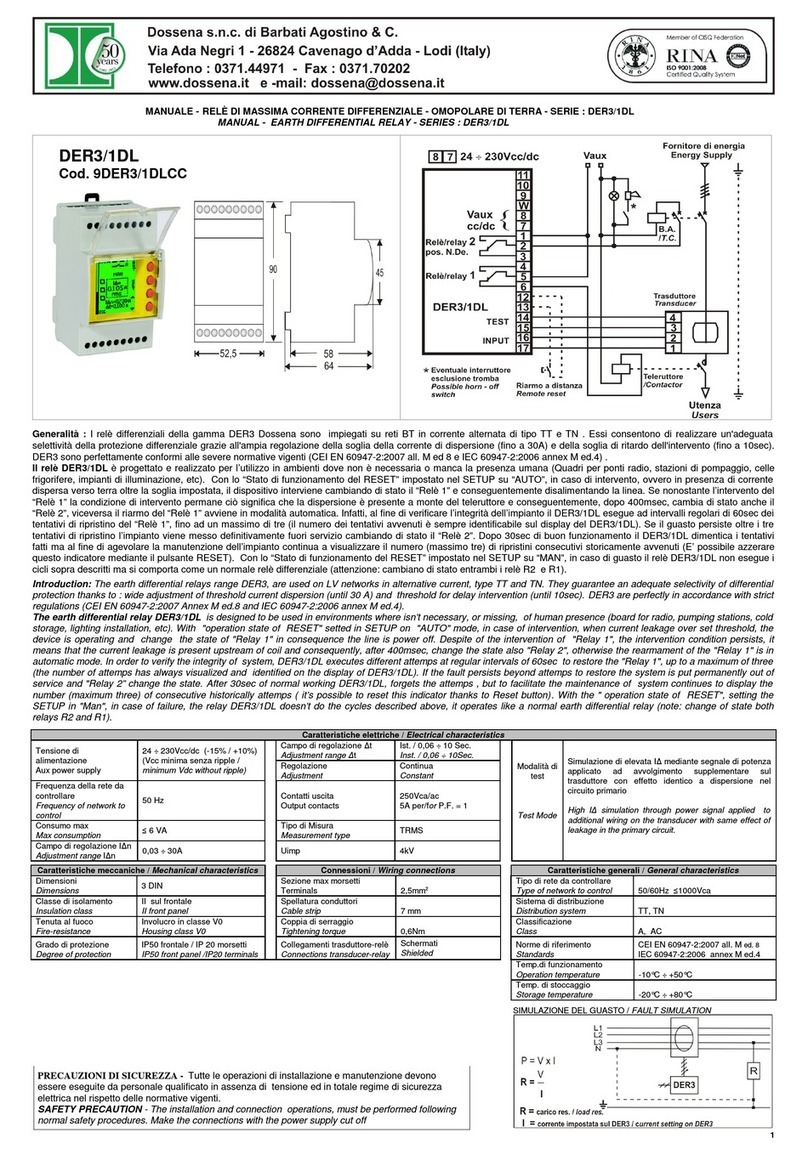
SEB IDM8N User manual

DIVISIONE ELETTRONICA E SISTEMI
IDM8N
DIGITAL PERCENTAGE BIASED
DIFFERENTIAL PROTECTION RELAY
USER MANUAL
P501D812 June 2010


SEB Divisione Elettronica e Sistemi INDEX
INDEX
1GENERAL CHARACTERISTICS..................................................................................1
1.1 Operation of the differential thresholds..................................................................3
1.2 Transformer differential protection (ANSI 87T)......................................................6
1.3 Overcurrent thresholds (ANSI 51) .........................................................................6
1.4 Residual overcurrent (ANSI 51N) ..........................................................................7
2FRONT PANEL KEYS ..................................................................................................8
3FRONT PANEL LED SIGNALING ................................................................................9
4PROGRAMMING AND TEST .....................................................................................10
4.1 How to program the protection relay....................................................................10
4.2 How to modify a visualized parameter.................................................................11
4.3 Reset ...................................................................................................................11
4.4 Test of output relays ............................................................................................12
5DISPLAY AND PROGRAMMING ...............................................................................13
5.1 Standard display..................................................................................................13
5.2 Visualization structure .........................................................................................14
5.3 Address and time (fig. 1) .....................................................................................19
5.4 Display selection and drop-off delay (fig. 1).........................................................20
5.5 Rated values of the protected transformer (picture 2) .........................................21
5.6 Thresholds and time delays set-up (fig. 2)...........................................................24
5.6.1 Percentage biased differential thresholds (87T - fig. 2) ................................24
5.6.2 Overcurrent thresholds (51 - fig. 2)...............................................................27
5.6.3 Residual overcurrent thresholds (51N - fig. 2) ..............................................28
5.7 Output relays programming (fig. 3) ......................................................................29
5.8 Digital inputs function programming (fig. 3) .........................................................30
5.9 Parameter values visualization (fig. 4).................................................................31
5.10 Events (fig. 5) ......................................................................................................35
5.11 Trips counters (fig. 5)...........................................................................................38
6INSTALLATION ..........................................................................................................40
6.1 Supplied kit..........................................................................................................40
6.2 Cabling ................................................................................................................40
6.3 Relays R3 and R4 - Signaling / Command set-up ...............................................46
6.4 RS485 serial communication port........................................................................46
7TECHNICAL DATA.....................................................................................................47
8TABLE ........................................................................................................................48
Information printed in this manual subject to change without prior notice.
This manual must not be reproduced in whole or in part, in any form or by any means
without the express written permission of SEB Divisione Elettronica e Sistemi.

SEB Divisione Elettronica e Sistemi GENERAL CHARACTERISTICS
1
1 GENERAL CHARACTERISTICS
The protection relay IDM8N performs function as three-poles percentage biased
transformer differential protection relay (ANSI 87T) to protect transformers or generator-
transformer units; the user can select one or more of the functions listed in the table below:
FUNCTIONS ANSI
Three-poles percentage biased differential protection for
transformers 87T
Three-poles overcurrent protection 51
Residual overcurrent protection 51N
Each function is made by a set of threshold, which could be enabled or disabled in
independent mode.
THRESHOLDS - the following thresholds are available:
•1 differential percentage biased threshold (two branches)
•1 absolute value differential threshold
•6 overcurrent thresholds (three for each winding of the transformer)
•3 residual overcurrent thresholds (secondary side)
The available settings for each threshold are listed in Table B.
All the set-up and measured parameters can be visualized on the front panel display and
transmitted on the RS485 communication serial port.
TRIP DELAYS - All the thresholds are time definite. Relay trips are shown turning on LED
and with a specific message on the display.
The available settings for each timers are listed in Table B.
OUTPUT RELAYS - the IDM8N controls 4 output relays (named R1, R2, R3 and R4);
these relays can be programmed to be activated on START or TRIP conditions of one or
more thresholds.
START instantaneous activation of the output relay when at least
one of the measured current or parameter exceeds the
programmed threshold value
TRIP activation of the output relay when the programmed time
delay (TI) related to a threshold expires.
The quiescent state of each single relay R1, R2, R3 and R4 can be programmed as
normally energized (ON) or normally de-energized (OFF). An additional relay R5 (normally
energized) is controlled by the self-diagnosis routines to report detected fault conditions.
Related to each threshold, partial and total counters of TRIP conditions are available.

SEB Divisione Elettronica e Sistemi GENERAL CHARACTERISTICS
2
DIGITAL INPUTS - there are available 6 digital inputs to activate the following functions
(when enabled by the programmed set-up):
•on/off ANSI function
•on/off thresholds (single threshold or all thresholds)
•STATO function (recording of measures on external event)
For each digital input can be programmed the condition that activates the related
functions:
HI voltage = > 20V dc / ac
LO voltage = 0 ÷ 10 V dc / ac
The digital input acquisition is valid when the voltage value stays in the range HI or LO for
at least 40 ms.
DISPLAY OF MEASURES - the user can select the continuous display of a measured
differential current or of a stabilizing current (primary values or relative values); all the
measured currents can be transmitted to an external controller through the RS485 port.
EVENTS - information related to the last 8 events (TRIP or STATO) are recorded in the
EEPROM memory.
Information includes the threshold set-up and activated relays (TRIP event only), the
measured currents, the digital input status, date and time of the event.
SELF-DIAGNOSIS - the software includes a non stop monitoring module that controls the
functionality of all hardware and software resources of the protection relay.
Detected fault conditions are reported by:
•diagnostic message on the display
•glow of a red LED on front panel
•R5 output relay drop-off
The fault condition signaling stays until faults are pointed out by the monitoring module;
during this condition the protection functions are suspended to avoid unsuitable tripping.
STATUS FUNCTION - when the STATO function is activated by one of the digital input
(when programmed) the protection relay memorizes information related to measured
currents and digital input status (see par. 5.10 - EVENTS). The recorded information
allows an analysis of trip causes in co-operative protection relays systems.
REMOTE COMMUNICATION - the opto-insulated serial port RS485 can communicate
with a personal computer or a remote control and monitoring system equipped with an
RS485 interface or with a standard RS485/RS232 converter.

SEB Divisione Elettronica e Sistemi GENERAL CHARACTERISTICS
3
It is possible to select the communication standard between STANDARD (ASCII 7 bit -
Seb protocol) and MODBUS (ASCII mode, SLAVE).
All the set-up and measured parameters can be transmitted on the RS485 communication
serial port; when communication is active (LED REMOTE glows), the operator on front
panel can visualize the relay set-up but changes of parameters are disabled (ENTER and
buttons disabled).
1.1 Operation of the differential thresholds
The IDM8N relay performs functions as percentage biased differential protection relay for
two windings transformers; the tripping characteristic is presented in figure A.
A differential protection relay operates on the principle of current comparison and with a
healthy protected object the current leaving is the same as that which entered it. Any
measured current difference is a clear indication of a fault condition within the protected
zone.
Id - differential current - vectorial difference between the input current and the output
current of the protected object
''1'11 IIId −=
Three differential current values are computed, one for each phase; the differential
thresholds are verified for each differential current.
Ip - stabilizing current - half-sum of the vectors of the input and output currents of the
protected object used to stabilize the protection relay operations in presence of faults
external to the protected zone.
2
''1'1
1
II
Ip +
=
When short-circuit currents due to faults external to the protected zone are flowing through
the protected object it is possible to have measured differential currents due to current
transformer errors or saturation. The stabilizing current is used to stabilize the protection
relay operation in these conditions.
Differential thresholds
Two differential thresholds are available:
Id> percentage biased differential threshold
Id>> second differential threshold (absolute value)
The relay operates when:
threshold Id>> the following disequation is verified

SEB Divisione Elettronica e Sistemi GENERAL CHARACTERISTICS
4
>>≥ IdId
threshold Id> ALL the following disequations are verified:
>≥ IBId
()
IpPId ∗≥ 1
()
DIIpPId −∗≥ 2
where:
|Id| module of the differential current
|Ip| module of the stabilizing current
IB> insensibility threshold
P1, P2: slopes of the tripping characteristic
DI intersection of the P2 straight line with Id/In axis
The listed disequations define the operating characteristic as presented in figure A and
they are verified with all the differential currents (and their stabilizing currents) related to
phase currents.
The differential threshold Id>> and the second branch of the operating characteristic
related to Id> threshold (slope P2) can be programmed ON/OFF.
All the differential thresholds are definite time (0.03 ÷ 999.99 s).
The minimum activation time of the output relay is programmable in order to avoid short
commands to switchgears when CT’s saturate.
The differential thresholds Id> and Id>> are referred to the rated current of the protected
transformer normalized with the ratio of the installed CT’s in order that the value of
measured currents on the primary and secondary windings can be directly compared.
For this purpose, two coefficients named KTA1 and KTA2 are used. They are referred to
the primary winding and to the secondary winding of the transformer and they are the ratio
between the rated value of the CT and the rated value of the related circuit.
In other words:
1
1
1
In
In
KTA TA
=
Where InTA1 is the rated value of CT (for example: 300, in case of a 300 / 5 CT) and In1is
the rated value of the current in the primary side of the transformer, for example 250 A. In
this case the value of KTA1 is: 300 / 250 = 1.2
The same argument is valid for secondary winding parameters.

SEB Divisione Elettronica e Sistemi GENERAL CHARACTERISTICS
5
The secondary rated value of phase CT is selectable 1 A or 5 A for each side of the
transformer to be protected.
For its internal processing, the relay converts the measured currents as referred to 5 A
value. This operation is irrelevant for the user.
Threshold values are referred in terms of the rated current In of the corresponding
installed CT’s.
Operating characteristic - figure A

SEB Divisione Elettronica e Sistemi GENERAL CHARACTERISTICS
6
1.2 Transformer differential protection (ANSI 87T)
The protection relay IDM8N has been designed to provide three-poles percentage biased
differential protection function to transformer and generator-transformer units.
The relay IDM8N protects two windings transformers; in table A (see ref. D2) there are the
vectorial groups of the transformers which can be protected by the relay.
The insertion of the protection relay is presented in figure 6. The CT’s are installed on both
sides of the protected transformer; in the case of generator-transformer unit, the CT’s are
installed on the HV side of the transformer and on the star-point side of the generator.
The differential relay IDM8N does not require the use of intermediate current transformers
as the phase angle and the current amplitude compensation are carried out by the
protection relay itself; the compensation is function of the programmed characteristics
related to:
•coefficients KTA1 and KTA2
•power transformer vector group
•type of connection if the primary winding is Y (insulated or grounded)
The connection of the power transformer to the network may cause an inrush current
which can be several times the rated current and, with a time constant up to several
seconds. This transient condition appears as a differential current to the protection relay
and it would make the relay trip.
A relatively high content of second harmonic components is typical for the inrush current
while they are nearly absent in case of a short-circuit.
Likewise overexcitation conditions are cause of odd harmonic components (3rd and 5th).
To avoid unsuitable trips, on protection relay IDM8N it is possible to activate (ON/OFF)
and to program (in terms of % Id) two harmonic thresholds (on 2nd and 5th harmonic
components as the 3rd harmonic components are often eliminated through the use of delta
windings).
The harmonic stabilization is activated if at least for one of the phases the measured 2nd
and 5th harmonic content of the differential current exceeds the programmed thresholds;
when the harmonic stabilization is active, the trip related to Id> threshold will be blocked
The harmonic restrain does not effect the Id>> threshold operation.
1.3 Overcurrent thresholds (ANSI 51)
Six overcurrent thresholds are available and actionable, 3 for each side of the transformer,
to guarantee a back-up protection against faults external to the protected transformer or
generator-transformer unit. The function of the overcurrent thresholds is to give an
additional protection to the transformer if the fault condition has not been eliminated by
protection relays closer to the fault.
IH> 1
st primary winding overcurrent threshold
IH>> 2
nd primary winding overcurrent threshold

SEB Divisione Elettronica e Sistemi GENERAL CHARACTERISTICS
7
IH>>> 3rd primary winding overcurrent threshold
IL> 1
st secondary winding overcurrent threshold
IL>> 2
nd secondary winding overcurrent threshold
IL>>> 3rd secondary winding overcurrent threshold
All overcurrent thresholds are definite time; the available settings for each threshold and
time delays are listed in Table B.
Overcurrent threshold values of function ANSI 51 are referred in terms of the rated current
In of the corresponding installed CT’s.
1.4 Residual overcurrent (ANSI 51N)
Three residual overcurrent thresholds are available and actionable, to guarantee
protection against earth faults internal to the protected zone in the secondary side of the
transformer.
IE> 1
st residual overcurrent threshold
IE>> 2
nd residual overcurrent threshold
IE>>> 3rd residual overcurrent threshold
All residual overcurrent thresholds are definite time; the available settings for each
threshold and time delays are listed in Table B.
Residual threshold values of function ANSI 51N are referred in terms of the rated current
Ion of the earth CT.
Note: the relay has two inputs to measure the residual current, one with rated value 1 A
(D1-D2 on CB1) and one with rated value 5 A (D1-D2 on CB2). The earth CT has to
be connected to the inputs referred to its own rated value and the relay has to be
programmed according to the CT rated value (see rif. D11).

SEB Divisione Elettronica e Sistemi FRONT PANEL KEYS
8
2 FRONT PANEL KEYS
The 5 push-buttons on the front panel allow to visualize all the protection parameters and
to modify the protection set-up.
right arrow
down arrow
programming session activation or parameter confirmation
change or increment of the selected parameter
reset of the protection relay (rif. par. 4.3)
VISUALIZATION OF PARAMETERS
•all visualizations are circular and they can be displayed using the two arrow push-
buttons.
•the structure of the visualizations and their contents are showed in Figures 1, 2, 3, 4
and 5.
•when the sealable transparent front panel is installed only the arrow push-buttons
and the RESET push-button are accessible to prevent unauthorized modification of
the protection set-up.
MODIFICATION OF PARAMETERS
•remove the transparent sealable front panel to access ENTER and push-
buttons.

SEB Divisione Elettronica e Sistemi FRONT PANEL LED SIGNALING
9
3 FRONT PANEL LED SIGNALING
POWER
(green)
⊕auxiliary supply available
FAIL
(red)
⊕fault condition detected by SELF-DIAGNOSIS software
REMOTE
(red)
⊕communication session active on RS485 port
87
(red)
⊕trip condition on Id> or Id>> threshold (ANSI 87T)
51
(red)
⊕trip condition on overcurrent threshold IH>, IH>>, IH>>>, IL>,
IL>> and IL>>> (ANSI 51)
51N
(red)
⊕trip condition on residual overcurrent threshold IE>, IE>> and
IE>>> (ANSI 51N)
The last trip condition (threshold indication) is also shown on front panel display; if a trip of
function 87 or 51 has occurred, also the fault phases are shown on the display.
More information on trip condition is presented in the recorded EVENT (see par. 5.10).

SEB Divisione Elettronica e Sistemi PROGRAMMING AND TEST
10
4 PROGRAMMING AND TEST
The protection relay is easily programmable following the instructions in the next
paragraphs:
•HOW TO PROGRAM THE PROTECTION RELAY
•HOW TO MODIFY A VISUALIZED PARAMETER
All parameters can be freely modified; the proper protection set- up as required by the
plant management is submitted to the operator's judgment.
4.1 How to program the protection relay
The programmable parameters are showed in Figures 1, 2, 3, 4 and 5 at the following
references:
B2 ÷ B7 relay address (RS485) and date/time
C1 ÷ C4 display and drop-off time
D1 ÷ D11 rated values of the protected transformer
E1D ÷ E10D threshold set-up and time delays 87T
E1F ÷ E5F threshold set-up and time delays 51
E1R ÷ E5R threshold set-up and time delays 51N
G1 ÷ G14 output relays functions
H1 ÷ H6 digital input functions
S1 ÷ S22 partial trip counters reset
The programming sequence is the following:
1) SELECT the visualization (on display) of the parameter to be modified using the
arrow push-buttons
2) ACTIVATE the PARAMETER MODIFICATION session depressing the [ENTER]
push-button and modify the parameter value
3) END the parameter modification session depressing again the [ENTER] push-
button
4) REPEAT the procedure from 1) to 3) for all the parameters required to obtain the
new protection relay set-up
5) CONFIRM the new protection relay set-up at the visualization CONFIRM PROG?
(Figure 1, ref. J1) within 5 minutes depressing the push-buttons [ENTER], up to
visualize YES and [ENTER] again to confirm.
NOTE The protection relay continues to operate using the previous set-up until the new
set-up is confirmed as at point 5) above; the visualization of the modified
parameters before the new set-up confirmation is only temporary to allow an easy
definition of the new protection set-up.

SEB Divisione Elettronica e Sistemi PROGRAMMING AND TEST
11
If the new set-up is not confirmed within 5 minutes from the last pressed push-button, the
protection relay visualizes again the previous set-up (the parameters set-up that the
protection relay is still using).
4.2 How to modify a visualized parameter
When the parameter to be modified is visualized on front panel display do the following
sequence:
1) PRESS [ENTER] to activate the parameter modification session
If one or more parameters are modifiable, on the first of them will appear a blinking cursor.
If no parameters are modifiable, no blinking cursor will appear.
2) MODIFY THE PARAMETER pressing the arrow push-buttons and
when two parameters are modifiable, the push-button allows to
point-out the parameter to be modified (the selected parameter will
blink
when numerical parameters are pointed-out the push-button allows
to select the digit to be modified
increasing of the parameter
a) the digits are increased by 1 unit
b) the other parameters are presented following the selection
list
3) PRESS [ENTER] to end parameter modification session
The modification session is ended and the parameter stops to blink
NOTE if a numerical parameter is selected out of the accepted range (as shown in Table
D) when the push-button [ENTER] is pressed for few seconds an error message
will be displayed as:
Errore
nei dati
and the parameter will be displayed again with the former value.
4.3 Reset
When the push-button [RESET] is pressed, the protection relays returns to the standard
condition:
•reset of glowing LEDs

SEB Divisione Elettronica e Sistemi PROGRAMMING AND TEST
12
•drop-off of tripped relays
•reset of any parameter changed but not confirmed (parameters are shown as
confirmed at the end of the last programming session)
•display on STANDARD MODE (Figure. 1, ref. A1 - par. 5.1)
4.4 Test of output relays
When the output relays test is selected (Figure. 3, ref. G9) it is possible to command an
output relay (one at the time) to trip from the current status allowing functional tests on
electrical plants.
The output relays are activated with the following sequence:
1) SELECT THE VISUALIZATION of the desired output relay to be tested
TEST R1
OFF
2) PRESS [ENTER] to activate the test session; the message OFF will start to blink.
3) PRESS and the message on the display will change as:
TEST R1
ON
4) PRESS [ENTER] to command the instantaneous trip of the output relay (change of
the current status).
The relay will stay on the new condition until:
•the or [RESET] push-button is pressed
•the ENTER push-button is pressed and the sequence at points 3) and 4) is
repeated (presenting OFF condition)
The same procedure will be used for R2, R3 and R4 relays.

SEB Divisione Elettronica e Sistemi DISPLAY AND PROGRAMMING
13
5 DISPLAY AND PROGRAMMING
The contents and the structure of the displayed messages are shown in figures 1, 2, 3, 4
and 5; the references A1, B1, B2 etc. identify specific displayed messages in the figures.
5.1 Standard display
A1 - STANDARD DISPLAY
It is the standard displayed message without operator's intervention (no push-buttons
pressed for at least 5 minutes) or when the RESET push-button has been pressed.
The displayed information is function of the protection relay status.
NORMAL FUCTIONING
During this state the following information can be visualized (as defined by set-up):
Protection function (ANSI code) - the display shows the ANSI codes of the main functions
(87T – 51 – 51N).
Measured current and parameters - the display shows one of the measured currents or
one of the differential currents (IdR, IdS, IdT) or the stabilizing currents (IpR, IpS, IpT); the
information to be visualized is selected by operator (ref. C1).
The currents are visualized as primary value and/or relative value (In).
ON TRIP CONDITION
When a trip condition occurs the protection relay visualizes the TRIP message that
includes the threshold related to the trip; the displayed messages are as the following:
TRIP
Id> r
TRIP
Id>> rs
TRIP
IH> t
TRIP
IE>
The information of the trip, as well the glowing of the related LEDs, is displayed until the
[RESET] push-button is pressed.
For trip condition related to functions 87T or 51, it is shown also the information related to
the fault phase(s).
Note: information related to fault phase (R, S, T) is referred to the insertion diagram in
picture 6. In case of trip of threshold Id> or Id>>, the fault phase is according to
compensation factors related to the transformer’s vector (rif. D2).
If a new trip condition occurs, the displayed information will be updated; information related
to previous trips is recorded in EVENTS memory.
FAULT CONDITION
When a permanent or temporary fault condition is detected by the self-diagnosis module,
the following message is displayed:
FAIL
eeeeeeee

SEB Divisione Elettronica e Sistemi DISPLAY AND PROGRAMMING
14
The string eeeeeeee can be:
HARDWARE Detected fault condition on hardware or software resources of the
protection relay; all functions are suspended.
Corrective action - replace the protection relay and contact SEB post
sales service.
5.2 Visualization structure
ANSI 87T
51 51N
FAIL
eeeeeeee
TRIP
Id>
IdR
xx.xx In
IDM8N PROTOCOL
yyyyyyyy
BAUDRATE
nnnn
NR RELE
xxx
NR SERIE
zzzzzzzz
VERS SW
zz.zz
gg/mm/aa
hh:mm:ss
SET-UP VALORI
NOMINALI
SET-UP
TRAFO
TARATURA
SOGLIE
FUNZIONI
RELE
INGRESSI
DIGITALI
CONFERMA
PROG?..
MISURE E
EVENTI
STATO
SEGNALI
EVENTI
TOTALIZZ
SCATTI
A1
B1
VISUALIZZAZIONI
ALTERNATIVE
B2
J1
B3
Visualizzazione dati nominali della protezione
(Fig. 2)
Set-up parametro trasformatore protetto
(Fig. 2)
Visualizzazione taratura SOGLIE
(Fig. 2)
Visualizzazione set-up RELE'
(Fig. 3)
Visualizzazione set-up INGRESSI DIGITALI
(Fig. 3)
Visualizzazione STATO SEGNALI
(Fig. 4)
Visualizzazione EVENTI
(Fig. 5)
Visualizzazione TOTALIZZATORI
(Fig. 5)
B4 B5 B6 B7
Figure 1

SEB Divisione Elettronica e Sistemi DISPLAY AND PROGRAMMING
15
SET-UP VALORI
NOMINALI
DISPLAY
eeeeeeee
CONTRAST
LIV n
T-DROP
xx.xx s
SET-UP
TRAFO
N-AVVOLG
2
TR-TYPE
eeeeeeee
CS-AT
eeeeeeee
TA1P
zzzzz A
TA1S
n A
KTA1
x.xx
TA2P
zzzzz A
TARATURA
SOGLIE
87T
ccc
Id>
n.nn In
P1
xx %
P2 ccc
xxx %
Q
nn.nn In
Id>> ccc
zz.zz In
T Id>>
rrr.rr s
51
ccc
IH>
ccc
IH>
nn.nn In
IH>
vvvvvv A
T IH>
zzz.zz s
51N
ccc
IE>
ccc
IE>
n.nnn In
IE>
vvvvvv A
T IE>
zzz.zz s
Da FIGURA 1
C1
D1
E1D
E1F
E1R
C2
D2
E2D
E2F
E2R
C3
D3
E3D
E3F
E3R
D4
E4D
E4F
E4R
D5
E5D
E5F
E5R
D6
E6D
D7
D10
E7D
TA2S
n A
KTA2
x.xx
IoP
zzzzx A
IoS
n A
TH2 ccc
xx %
D8
D11
E8D
D9
A
lla FIGURA 3
MODO
DEBUG xx
C4
T Id>
zzz.zz s
TH5 ccc
xxx %
D10D
E9D
IL>>>
ccc
IL>>>
nn.nn In
IL>>>
vvvvvv A
T IL>>>
zzz.zz s
IE>>>
ccc
IE>>>
n.nnn In
IE>>>
vvvvvv A
T IE>>>
zzz.zz s
Figure 2

SEB Divisione Elettronica e Sistemi DISPLAY AND PROGRAMMING
16
FUNZIONI
RELE
R1
NORM ccc
R1 Id>
xxxxxxxx
R1 Id>>
xxxxxxxx
R1 TH2
xxxxxxxx
R1 TH5
xxxxxxxx
R1 IH>
xxxxxxxx
R1 IH>>
xxxxxxxx
R1 IH>>>
xxxxxxxx
R2
NORM ccc
R3
NORM ccc
R4
NORM ccc
INGRESSI
DIGITALI
DIG1 cc
xxxxxxxx
DIG2 cc
xxxxxxxx
DIG3 cc
xxxxxxxx
DIG4 cc
xxxxxxxx
DIG5 cc
xxxxxxxx
DIG6 cc
xxxxxxxx
CONFERMA
PROG?..
Da FIGURA 2
J1
G1
H1
G2
H2
G3
H3
G4
H4
G5
H5
G6
H6
G7 G8
R1 IL>
xxxxxxxx
G9
Alla FIGURA 4
R1 IL>>
xxxxxxxx
G10
R1 IL>>>
xxxxxxxx
G11
R1 IE>
xxxxxxxx
G12
R1 IE>>
xxxxxxxx
G13
R1 IE>>>
xxxxxxxx
G14
TEST R1
yyyyyyyy
G15
Figure 3

SEB Divisione Elettronica e Sistemi DISPLAY AND PROGRAMMING
17
MISURE E
EVENTI
STATO
SEGNALI
STATO
SOGLIE
Id>
stato
Id>>
stato
TH2
stato
TH5
stato
IH>
stato
IL>>>
stato
PARAMETR
TRAFO
Ka=
x.xx
Kb=
x.xx
Kc=
x.xx
Ear = xx
Far = xx
Gar = xx
Ebr = xx
Fbr = xx
Gbr = xx
Fbs = xx
Gbs = xx
Eat = xx
Fat = xx
Gat = xx
Ebt = xx
STATO
RELE
R1 ccc
R2 ccc
R3 ccc
R4 ccc
STATO
DIGITALI
DIG1 ww
DIG2 ww
DIG3 ww
DIG4 ww
DIG5 ww
DIG6 ww
STATO
MISURE
IR1=xx.x
yyyyy A
IS1=xx.x
yyyyy A
IT1=xx.x
yyyyy A
IR2=xx.x
yyyyy A
IS2=xx.x
yyyyy A
IT2=xx.x
yyyyy A
IdT =
xx.xx In
Id$ # =
xx.xx In
TH2R
nn%
TH2S
nn%
STATO
PASSANTI
IpR =
xx.xx In
IpS =
xx.xx In
IpT =
xx.xx In
Xr =
xx.xx In
Yr =
xx.xx In
Xs =
xx.xx In
Da FIGURA 3
L1
X1
M1
N1
P1
Y1
L2
X2
M2
N2
P2
Y2
L3
X3
X10
N3
P3
Q3
Y3
L4
X4
X11
P4
Q4
Y4
L5
X5
X12
P5
Q10
Y5
L10
X6
P6
Q11
Y6
IE>>>
stato
Eas = xx
Fas = xx
Gas = xx
Ebs = xx
Fbt = xx
Gbt = xx
IR=x.xxx
yyyyy A
IR1 2a
xx.xx In
IT2 5a
xx.xx In
TH2T
nn%
TH5R
nn%
TH5S
nn%
TH5T
nn%
Ys =
xx.xx In
Xt =
xx.xx In
Yt =
xx.xx In
L13
X7
P7
Q12
X8
P8
Q13
X9
Q14
P19
Q15
Y7 Y8 Y9
Alla FIGURA 5
IE>
stato
L11
IE>>
stato
L12
STATO
DIFFER.
IdR =
xx.xx In
IdS =
xx.xx In
Q1 Q2 Q9
X$ #a =
xx.xx In
Y21Y10
Figure 4
Table of contents
Other SEB Relay manuals
Popular Relay manuals by other brands
Rockwell Automation
Rockwell Automation Guardmaster MSR57P user manual
Omron
Omron G9SE-201 user manual
Rockwell Automation
Rockwell Automation Allen-Bradley 193-T1APM Installation instruction
Oppermann Regelgeräte
Oppermann Regelgeräte JVA manual
Circutor
Circutor WRU-10 quick start guide
Rockwell Automation
Rockwell Automation Allen-Bradley 440R-GL2S2T user manual
