EOS LSG 10 CA User manual

IPx4
Made in Germany
LSG 10 CA / CW LSG 10 ET
LSG 10
EN Installation and Operating Instructions
Contactor box
Print no. 29345277en / 26.22
Subject to technical changes

2EN
Manufacturer
EOS Saunatechnik GmbH
Schneiderstriesch 1
D-35759 Driedorf, Germany
Tel.: +49 (0)2775 82-0
Fax: +49 (0)2775 82-431
E-Mail: servicec[email protected]
Web: www.eos-sauna.com
Original installation instructions EN
Copyright for these installation instructions remains with
EOS Saunatechnik GmbH.
Copyright as per DIN ISO 16016:
The copying and distribution of this document, as well as the use and communication of its con-
tents without express authorisation, are not permitted. Compensation will be claimed in the event
of infringements.
All rights reserved with regard to patent claims or submission of design or utility patent.
Documentation

3
EN
English
Contents
General safety instructions
Safety levels............................................................................................................................................4
Mounting and electrical installation .........................................................................................5-6
Operator instruction .......................................................................................................................6-7
Standards and regulations................................................................................................................7
Identification .................................................................................................................................................8
Intended use..................................................................................................................................................8
Scope of delivery .........................................................................................................................................9
Technical data ...............................................................................................................................................9
Installation
Installation site................................................................................................................................... 10
LSG 10 CA / CW - installation details ...................................................................................11-15
LSG 10 ET - installation details................................................................................................16-18
Electrical connections
Board layout and overview of connections............................................................................. 19
Terminals and connections ........................................................................................................... 20
Recycling...................................................................................................................................................... 21
Service address.......................................................................................................................................... 21
General terms and conditions of service ........................................................................................ 22

4D
Safety instructions and important operating instructions are classied. Please familiarise yourself
with the following terms and symbols:
WARNING
Warning
Indicates a hazardous situation which, if not avoided, could result in death or serious injury.
CAUTION
Caution
Indicates a hazardous situation which, if not avoided, could result in minor or moderate in-
jury.
NOTICE
Notice
Indicates a hazardous situation which, if not avoided, will result in damage to the unit.
General safety instructions
Safety levels

5
D
Mounting and electrical installation
These installation instructions are intended for qualied personnel familiar with
the laws and regulations applicable to electrical installations at the installation
site. Observe the following general safety instructions during mounting, cong-
uration and commissioning of the product.
Risk to life and limb and risk of re
Risk to life and limb from electric shock and re in the event of improper or faulty electrical
connection. This risk also applies following completion of the installation work.
• The electrical installation of the relay box and other electrical systems or equipment with
a xed mains connection must only be performed by a trained electrician from an author-
ised electrical company.
• Observe the stipulations in VDE 0100 part 703 or the applicable local legal requirements.
• The system must be completely disconnected from the mains supply before commencing
installation and repair work.
• The housing cover must only be removed by a specialist.
Fire hazard from overheating
Insucient ventilation can lead to device overheating and re.
• Do not install control panels, relay boxes and modules in enclosed cabinets or wood pan-
elling.
• Observe the sauna heater and control unit manufacturer’s safety and installation instruc-
tions.
• Observe the cabin manufacturer’s safety and installation instructions.
Damage to the unit
Corrosive or heavy saline atmospheres damage the contacts in the control panel, in the relay
box and in the sensors.
• The device should not be installed in a corrosive or heavy saline atmosphere.

6D
Damage due to incorrect mounting location
The device is not suitable for outdoor use!
• It may be operated only inside buildings and may not be exposed to environmental condi-
tions such as extreme humidity and moisture or the possible formation of condensation or
corrosive substances in the ambient air, as well as other weather conditions.
• Similarly, excessive cold and extreme exposure to sunlight must be prevented.
• Protect the unit accordingly if there is an increased risk of mechanical damage.
Operator instruction
The operator of the infrared or sauna cabin must be instructed on the general safety instruc-
tions during commissioning.The operator must be given a copy of the operating instructions.
The operator must make the end user aware of safety instructions that are relevant to the
end user.
Risk of electric shock
A risk to life and limb from electric shock and re arises in the event of improper repair work.
This risk also applies after work is completed.
• The housing covers must only be removed by a specialist.
• Repairs and installations may only be performed by a trained specialist.
• The system must be completely disconnected from the mains supply before commencing
repair work.
• Use only original spare parts from the manufacturer.
Operation by children or persons with reduced mental capacity
Children and persons with reduced mental capacity can put themselves at risk.
• Children must be supervised to ensure they do not play with the unit.
• This device is not intended to be used by children or by persons with reduced mental ca-
pacity, or limited physical or sensory abilities.
• Children and persons who have not received proper instruction must not clean or service
the system.

7
D
Standards and regulations
For an overview of the standards that were observed during design and construction of
the sauna heaters, please refer to the individual product‘s technical data sheet that can be
downloaded from www.eos-sauna.com.
Local regulations also apply to the installation and operation of heating, sauna, and steam
room systems.

8EN
Identication
Intended use
The LSG10 device is a relay box for power extension of sauna control units and in conjunction with
a sauna heater is used to operate a sauna cabin.
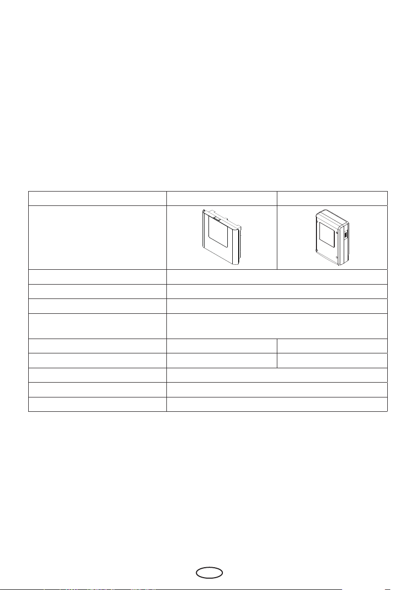
Identification
The nameplate is attached to the underside of the base of the housing.
The LSG device in conjunction with a suitable control unit and a sauna heater control unit is intended
to be used only to heat sauna cabins. It is suitable for cabins used in private and commercial settings.
The device is intended only for mounting on the wall.
The device is not suitable for outdoor use. It must be operated only inside buildings
and may not be exposed to environmental conditions such as extreme humidity and
moisture or the possible formation of condensation or corrosive substances in the
ambient air, as well as other weather conditions. Similarly, excessive cold and extreme
exposure to sunlight must be prevented. Protect the unit accordingly if there is an
increased risk of mechanical damage.
Foreseeable misuse
The following are considered instances of foreseeable misuse:
• Incorrect electrical connection.
• The unit is operated without knowledge of or compliance with the safety instructions.
• Operating, service and maintenance requirements are not observed.
• The unit is operated after technical or other modications are made to the relay box.
• The unit is operated by children or persons with reduced mental capacity
• or by persons who have not been thoroughly instructed in its use.
The manufacturer is not liable for unauthorised modications made to the equipment and dam-
ages resulting from these modications. The person modifying the equipment alone shall bear the
associated risk.
See also the General Safety Instructions.
Leistungsschaltgerät
Type EOS LSG 10
Art. Nr. 94 xxxx 00
400V 3N ~ 50 Hz
max. Schaltleistung 10 kW
Made in Germany 00002S-No. 50.21
EOS SAUNATECHNIK GmbH, Schneiderstriesch 1, 35759 Driedorf
IPX4
A
B
C
D
E
F
G H
AName
B Model
CItem number
DOperating voltage and voltage
ECountry of origin
FManufacturer
GManufacturing date
HSerial number

9
EN
Technical data
Typ LSG 10 CA/CW LSG 10 ET
Model
Voltage (power supply): 400 V 3N ~ 50 Hz
Switching output max. 10 kW
Fuse protection (power supply) 3 x 16 A
To be used with the control units EOS Econ, Compact, EmoTec, EmoStyle, EmoTouch 3
series
Dimensions (H x W x D) 220 x 255 x 65 mm 270 x 190 x 90 mm
Weight approx. 1,2 kg approx. 1,5 kg
Protection class IPx4 water splash protection
Ambient temperature -10°C to +40°C
Storage temperature -20°C to +60°C
Check the device for completeness upon receipt.
The delivery includes:
• 1 power extension unit
• 1 plastic bag with
8 rubber cable glands
3 mounting screws
• 1 installation and operating instruction
Scope of delivery

10 EN
Installation
This chapter describes how to install the relay box, the control panel and the most important com-
ponents.
Cables to connect sauna heater, vaporizer (steam generator) or another heating system, light-
ing(s), fan(s) or other components must have appropriate cross section.
All electrical installations and all connecting lines that are installed inside a cabin must be suitable
for an ambient temperature of at least 170°C and protection class IPx4 or be suitable for use in a
steam room (IP 65).
All lines must be routed in such a way that they are well-protected, e.g. in a cable duct.
NOTICE
NOTICE
Damage due to incorrect mounting location
The control unit is not suitable for outdoor use!
• It must be operated only inside buildings and may not be exposed to environmental conditions
such as extreme humidity and moisture or the possible formation of condensation or corrosive
substances in the ambient air, as well as other weather conditions..
• Similarly, excessive cold and extreme exposure to sunlight must be prevented.
• Protect the unit accordingly if there is an increased risk of mechanical damage.
Electronics malfunctions
Routing data and power supply lines together can lead to electronics malfunctions because, e.g.
because the sensor will not be detected.
• Do not route sensor and sauna bus lines together with power supply lines.
• Route cable conduits separately.
Requirements for installation site
• Ambient temperature during operation -10°C to +40°C
• Relative air humidity during operation 30% to 75%
• Ambient atmosphere must not be corrosive or have high salt content
• Ambient storage temperature -20°C to +60°C
• Stable wall surface
• Near the place of installation: power supply 400 V 3N ~
• All cables and connections must be accessible for servicing.

11
EN
Proper and improper mounting of the control unit
WARNING
Risk to life and limb and risk of fire
Risk to life and limb from electric shock and re in the event of improper or faulty electrical con-
nection. This risk also applies following completion of the installation work.
• Do not mount the device in enclosed cabinets or wood panelling.
The device must be installed only outside of the sauna cabin. Recommended installation locations
are:
• Outer wall of the sauna cabin, however not outside of the building
• Plant room or a similar suitable place
If empty conduits for electrical installations are already present, this dictates the position of the
relay box.
Installation site
Guidelines
LSG 10 CA/CW - Installation

12 EN
Installation preparation
Remove the front cover from the housing.
• Unscrew the screw on the top of the housing.
• Swivel the front cover and remove it downward.
Removing the front cover
Notice: Remove the protective film from the panel after mounting is
completed.
1. Determine the mounting site.
2. Route the lines.
Wall-mounting installation
1. Drill one (1) hole above and two (2) holes below.. Note the distances as indicated.
~ 62 cm
16,5 cm
16,5 cm

13
EN
165
165
165
165
3
165mm
165 mm
3 mm
3. Prepare the line openinings in the housing
by breaking the corresponding plates at the
rear or at the bottom side.
4. Insert the supplied bushings into the prepa-
red openings.
5. Draw the connection cables into the control
unit through these openings.
Dimensions in mm
6. Hook the housing into the upper screw using
the upper mounting hole.
A
A. Openings for power supply line, heater line, con-
trol unit line
2. Insert and tigthen the upper screw, use
dovel if necessary. Allow the screw to prot-
rude approx. 3 mm so you can hook in the
housing.

14 EN
Aoberes Befestigungsloch
Buntere Befestigungslöcher
A
B B
7. Securely tighten the housing in the two
lower mounting holes (B).
8. Connect power supply and consumers (see
Electrical Installation).
9. Finally mount the front cover back on the
control unit and secure it at the top with the
mounting screw.
Semi-recessed installation
1. Prepare a wall cut-out (height x width 198 x 215 mm as indicated)
2. Drill 4 holes:
a) Set the housing in the wall cut-out..
b) Use a pencil to mark the four drill holes in the tabs.
c) Remove the housing.
d) Drill four holes.
~ 62 cm
21,5cm
19,8 cm

15
EN
198
215
0,5
0,5
35
ATabs with mounting holes for screws
A
A
A
A
Dimensions in mm
3. Prepare the line openinings in the
housing by breaking the corresponding
plates at the rear or at the bottom side.
4. Insert the supplied bushings into the pre-
pared openings.
5. Draw the connection cables into the con-
trol unit through these openings..
6. Insert the housing into the wall cut-out
and secure it with 4 screws as indicated.
7. Connect power supply and consumers
(see Electrical Installation).
8. Finally mount the front cover back on
the control unit and secure it at the top
with the mounting screw.

16 EN
Proper and improper mounting of the control unit
BB
A
ATop mounting hole
BLower mounting holes
LSG 10 ET - Installation
Guidelines

17
EN
1.
Installing the relay box
Necessary steps:
1. Preparing for installation
• Determine a suitable locati-
on for the installation.
• Route the lines.
2. Removing the housing cover (see Fig.)
• Loosen 4 screws in the front cover panel.
• Removing the housing cover
3. Installing the relay box
• Drill one hole above and two holes below.
Horizontaldistancebetweendrillholes:130mm
Vertical distance between drill holes: 180 mm
• Insert the dovels as needed and screw in the top screw. Allow the screw to protrude approx.
3 mm so you can hook in the housing.
~ 62 cm
13 cm
18 cm

18 EN
130
180
3
1.
2.
ALines with mains voltage,
e.g. mains supply line, heat system, light
BConnection line to sauna control unit
4. Open the relay box conduits for the lines.
5. Insert supplied rubber grommets into the openings of the lower part of the housing..
6. Route the connecting cables through the openings.
A B
7. Hook the relay box into the upper screw using the upper mounting hole.
8. Securely tighten the relay box using the two lower mounting holes.
• Once you have completed all installation work you can connect the consumers and plug in
the lines.
• Connecting data lines (Elektroinstallation).
• Connecting and configuring consumers (Elektroinstallation).
9. Finally mount the front cover back on the control unit and secure it with 4 screws.
Dimensions in mm

19
EN
This chapter describes how to connect lines to the LSG device’s circuit board.
You can connect sauna heaters for dry Finnish sauna and also Bi-O type heaters. By Bi-O type heat-
ers only the heater section connects to the LSG device. The vaporizer should be connected to the
sauna control unit.
The LSG device is connected with a live current of 400 V 3 N ~ 50 Hz and fused separately with 3 x
16 A. A 16 A cut-out with at least K characteristic must be used for fuse protection.
As a rule, only a xed connection may be connected to the mains supply, whereby a conguration
is provided that makes it possible to separate the system from the mains supply with a contact
opening width of at least 3 mm (all poles).
Recommended installation sequence:
• Connect the sauna heater.
• Connect the control unit.
• Connect the power supply line.
The total power load of connected consumers must not exceed 16 A current per phase.
Circuit board assignment and general overview of connections
Connections
Electric connections
PE
max. 10 kW max. 9 kW (10 kW*)
PE
LSG
V N S1 V1 N S1
L1 L2 L3 N
L1 L2 L3 N
N W V U L1 L2 L3 N
L1 L2 L3 N PEPE
W V U N
LSG 10 Steuergerät
Control unit
Tableau de commande
Notice: Control unit shows only the ter-
minals relevant for this connection.
* 10 kW - for EOS Compact DP, HP, DC, HC

20 EN
All lines must be connected to the corresponding terminals. Heat-resistant cables must be used for
the sauna heater connection.
WARNING! Ensure that the LSG relay box has no power.
Draw the lines into the unit through the knock-out openings and proceed with the connections.
Sauna heater
Connect the sauna heater to the terminals (B).
Control unit
Connect the control unit line to the terminals (C).
Power supply
Connect the power supply 400V 3N ~ to the terminals (A).
Once all connections have been made, mount the front cover and secure it (see also Installation).
Terminals
WARNUNG
Risk of electric shock
A faulty electrical connection poses the risk of an electric shock. This risk remains also after com-
pletion of the installation work.
• Disconnect the system entirely from the mains supply.
• If retrotting is required, the housing must only be opened by trained personnel.
• Electrical installation must only be carried out by a qualied and licensed electrician.
• The unit must be connected to the power supply according to the circuit diagram and the
terminal scheme.
PE
V N S1
L1 L2 L3 N N W V U
MAINS OVEN CONTROL
B CA
A. Power supply
B. Sauna heater connection
C. Control unit connection
This manual suits for next models
2
Table of contents
Other EOS Relay manuals