International Gas Detectors TOC-635 Assembly instructions

FS646773 EMS696504
Triton House
Crosby Street
Stockport
SK2 6SH
@
Document Ref: SL-016 V4.85
FS646773 EMS696504
Installers Guide
2-Wire Systems
internationalgasdetectors.com
+44 (0)161 483 1415
/international-gas-detectors-ltd
International Gas Detectors
2 - W I R E S Y S T E M S
Gas Detection Installers Guide
Please Refer to Specific Controller
Manual and Full Version
Installers Guide.
TOC-635
TOC-650
TOC-750

2-WIRE
GAS DETECTION
www.internationalgasdetectors.com
Display
&
Volt Free
Relay
Analogue in
Analogue in
Sounder
Output
Digital Out
Digital Out
or
or
Gas
Gas
Detector
Detector
Each Detector Node Has Multiple I/O
ALL
OK
First Fit Cabling
Fit Detector Nodes
Fit Additional Devices
Where You Need Them
Safety Assured
CO H2S LPG
4-20
Addressable
2-Wire
WiFi Setup and Service Tools
2 Core Cable Connects Detector Nodes
No Cable Polarity
350 Detector Nodes/Devices Possible
IOT Options, see alarms & data anywhere
Modbus Compatible
Battery Backup
FS646773

This installers guide is intended for the use of system specifiers, surveyors, designers and installers.
The intention of this guide is to provide information for the correct installation of IGD’s range of 2-Wire
gas detection systems. This guide indicates correct cabling practice, types of cabling which can be
used and options available to correctly design and install a 2-wire gas detection system. This guide is
not intended as a design or specification guide, these are available separately.
Note that System control panels, detector nodes, battery backup modules and power boosters are all
supplied with their own manuals. Their general specifications and performances are available both in
their individual manuals and published data sheets. This data is not reproduced in this guide.
Failure to follow this installers guide could compromise operation of the 2-Wire gas detection system
so please follow the enclosed information carefully.
Systems should be designed and installed by competent persons. A competent person being defined
by the UK Health and Safety Executive as:
A competent person is someone who has sufficient training and experience or knowledge and other
qualities that allow them to assist you properly. The level of competence required will depend on the
complexity of the situation and the particular help you need.
IGD’s gas detection systems are capable of installation by electrical installation engineers. Design of
a system is not covered in this guide and should be undertaken by a competent person. The design
should include:
The Nature of the Gas Hazard and Appropriate Placement of Detectors
Clear Indication to workers That a Gas Hazard Exists and the Action They Must Take
Interaction Between the Gas Detection System and Other Systems
The Necessary Safe Operating Procedures That Must be in Place
IGD can provide help to design systems where help is required and can also provide training for
surveyors, specifiers, designers and installers.
All Gas Detectors shipped from IGD are pre-calibrated. It is not always necessary to re-calibrate a
newly installed system on site but it is recommended that commissioning is undertaken.
Commissioning should be undertaken by persons trained to do so. Commissioning should ensure that
the system performs and interfaces correctly to all connected devices, host systems and operates to
the required cause and effect.
IGD are available to answer question using our on-line ticketing system available through our website.
NOTE that ATEX equipment has specific requirements for cable protection and glanding to housings.
These requirements are detailed in manuals for such equipment available through our website.
INTRODUCTION

SECTION 1
MOUNTING DETAILS FOR EQUIPMENT

TOCSIN 750 PHYSICAL
Installation Cables
382mm
292mm
72mm
120.5mm
267mm
20mm
48.5mm
Front Face
Top Face
Side Face
56.5mm
30mm
10 off 20mm
Cable Entries
360mm
Supported Installation Cables 2 Core 1.5mmSQ or 2.5mmSQ See IGD Cable System Calculator
Typically SWA, FP200, CY, screened or Similar
Note 150W and 24V DC Versions Can be
Flush mounted into walls up to the front face flange
300W Versions have active ventilation and must be
surface mounted allowing 100mm clearance all round
Note that the rear case can be rotated to allow
20mm entries to face either up or down
Addressable
2-Wire
FRONT VIEW

Installation Cables
382mm
292mm
72mm
120.5mm
267mm
20mm
48.5mm
Front Face
Top Face
Side Face
56.5mm
30mm
10 off 20mm
Cable Entries
360mm
Supported Installation Cables 2 Core 1.5mmSQ or 2.5mmSQ See IGD Cable System Calculator
Typically SWA, FP200, CY, screened or Similar
Note 150W and 24V DC Versions Can be
Flush mounted into walls up to the front face flange
300W Versions have active ventilation and must be
surface mounted allowing 100mm clearance all round
Note that the rear case can be rotated to allow
20mm entries to face either up or down
FRONT VIEW Addressable
2-Wire
TOCSIN 750 PHYSICAL

185mm
238mm
215mm
Front Face
Bottom Face
Side Face
5 off 20mm
Cable Entries
210mm
75mm
42mm
19mm
80mm
TOCSIN 635 MICRO AND PLUS PHYSICAL
Addressable
2-Wire
Weight: 2.7kg
TOCSIN 750 PHYSICAL
Installation Cables
Supported Installation Cables 2 Core 1.5mmSQ or 2.5mmSQ See IGD Cable System Calculator
Typically SWA, FP200, CY, screened or Similar

The ATEX version uses IGD’s JB3 series ATEX EXD terminal enclosure. Please note that cable glanding
and sealing must conform to ATEX requirements which is more fully described in the ATEX JB3 manual
Mounting Details and Dimensions Safe Area Versions
Gas Detector Types
172
158
76
48
43
86
98 18
5
20mm Entries Top, Bottom & Either Side
Note TOC-750-AN3 Shown
Detectors, Annunciators and
Nodes Share Common
Mounting Details
145.0
126.0 128.5
COVER SECURING SCREW
M20 x 1.5
40.0
25.0
Ø7.0
EXTERNAL EARTH
MKIII FLAMMABLE
GAS DETECTOR
SHOWN
40.0
Ø110
128.0
Refer to individual data sheets for specific data relevant to available gas detectors, types,
accuracies and sensitivities available.
For pellistor type gas detectors complying to BS EN 60079-29-0 and 1, these general purpose
flammable gas detectors are suitable for Methane and LPG detection in the range 0-100% LEL.
Relative response to Methane @ 4.4% Vol = 100% LEL Equivalent to 48.4% LEL N-Butane
ATEX MOUNTING DETAILS
& DIMENSIONS

FRONT VIEW
382mm
292mm
72mm
120.5mm
267mm
20mm
48.5mm
Front Face
Bottom Face
Side Face
56.5mm
30mm
10 off 20mm
Cable Entries
360mm
TOC-750-BAT1 7AH Battery Backup with 150W PSU
TOC-750-BAT2 17AH Battery Backup with 300W PSU
460mm
292mm
115mm
20mm
Front Face
Bottom Face
Side Face
25mm
60mm
95mm
4 off 20mm
Cable Entries
BATTERY BACKUP MODULES

SECTION 2
SITING GAS DETECTORS

Gas detectors usually fall into two groups for placement
1. Plant Protection. Typically flammable gas detectors fall into this category. Aside from asphyxiation
flammable gases are typically not directly toxic and so detectors are placed strategically where the gas is
expected to accumulate based on its relative density to air (lighter or heavier)
2. Life Safety Systems. Here the concern is that a toxic or asphyxiant gas is directly hazardous to
personnel and so the gas detection is placed based on the normal operating zone for the people present
Note that in many cases both life safety and plant protection sensors may be appropriate on a site. For
example a plant using liquid helium may have plant protection sensors at high level to ventilate roof
spaces in the event of leaks. However in the event of ventilation failure Helium could accumulate down
towards the zone where personnel operate. In this case a second set of life safety sensors would be
appropriate.
Each site should be surveyed and assessed on its own merits. This document presents general
guidance only.
Lighter than air gases, detectors placed at highest ceiling points
Consider fitting collector cones at lower level for gas bottle stores
boiler plant and gas meters (see separate application note).
400mm
1000mm
1800mm
Life Safety Zone
Consider ceiling divisions, follow rules for smoke detectors
Methane, Helium, Hydrogen, Ammonia etc
LPG, CO2
CO, CO2, O2
H2S, NO2, NO
HCN, HCL, HF
NH3 etc
Consider fitting splash/dust guards to protect low level sensors
Consider sensors in under floor areas/voids/drains where heavier than air gases are present
LPG 0-100%LEL
SN:20235-1-1 ADD:4110
GAS DETECTOR
LPG 0-100%LEL
SN:20235-1-1 ADD:4110
GAS DETECTOR
SITING GAS DETECTORS

High Concentrations Local to Release Source or Cloud Development Scenario
5M
100%
CO2
For this CO2 Example
Expect Higher
Concentrations at Low
Levels. Use for
Ventilation Trigger and
Pre-Alarms
For this CO2 Example
use Detectors in
the Life Safety Zone
to Trigger Ventilation
and Evacuation Alarms
5M is a Maximum Detection Distance and
Will be Effected by Topography.
Gas Levels Will Drop as Distance to Leak
Source Increases Requiring Lower Alarm
Set Points
Heavier Than
Air Gases Can
Show a Gradient
in Room Levels
With Higher
Concentrations at
Floor Level or
Slow Leak Scenario
This Example Illustrating
A CO2 Gas Release From
A Storage Cylinder. Typical
Scenario, Broken or Blown
off Hose, Regulator Incorrectly
Connected, Ruptured Gauge
or Similar.
SITING GAS DETECTORS

In a similar manner to smoke detectors, a gas detector can provide up to 75SQ M area coverage based on
a 5M radius of operation. There are many factors affecting this, geometry of a room, equipment in the area,
gas characteristics, ventilation air flows etc. IGD can support throughout the survey, design and installation
process to ensure the best possible result on site.
All gas detection systems require regular checking and calibration to be in compliance with the UK
factories act. The service and calibration period will be a function of the application based on
environmental in service conditions. It is extremely important to ensure a service plan is in place for any
gas detection system installed as part of a site safety system. IGD can work with operators to provide
advice, service and spares to ensure an appropriate level of cover.
Applications involving Cryogenically cooled gases such as liquid Nitrogen or Helium need careful
consideration for gas detection. On initial release as cryogenically cooled gases can typically be at lower
temperature and high density than their surroundings they will behave differently than when in their
gaseous state. In such cases it should be considered if two sets of detection is required, one for the life
safety zone and one for low level detection in the gases cooled state. Applications involving such gases
are recommended to be surveyed.
Typically up to 75 SQ M Coverage
Max 5M Radius
Typically up to 75 SQ M Coverage
Max 5M Radius
CRYOGENIC GAS DETECTION
AREA COVERAGE FOR GAS DETECTORS
CALIBRATION & SERVICE REQUIREMENTS
FOR GAS DETECTION SYSTEMS

Detectors should be
mounted vertically with the
sensor face facing
downwards to protect from
contamination.
Sensor Facing Down
Sensor Mounted to Vertical Wall in Various Orientations
Do NOT Mount With The Sensor Facing Upwards
GENERAL MOUNTING POSITIONS
ATEX (BS EN 60079-29-1)
GENERAL MOUNTING POSITIONS
SAFE AREA (BS EN 50194)

Detectors in Airflows Mounting Positions Atex (BS EN 60079-29-1)
Do NOT mount Detectors Where
Airflows Are Likely to be Directed
either onto or Away From the Sensor
Face. This Situation May Result in
Contamination and/or reduced
Detection Capability
Air Flows up to 6M/S Are
Allowable Without Any
Performance Issue Across
the front of The Sensor Face
Air Flows up to 1M/S Are Allowable Without Any Performance Issue
Detectors in Airflows Mounting Positions Safe Area (BS EN 50194)

Control Panels
These should be located outside of the area protected by its connected
gas detectors.
The control panel should be accessible such that in the event of an
alarm the area can be evacuated and gas levels viewed from the
controller.
Consider the use of mimic panels, HMI panels or GSM options available
from IGD to provide additional remote indication/alarm
Audio-Visual alarms
As a general rule if there is gas detection fitted to an area then there
should be an audio-visual alarm (beacon sounder) to alert personnel
who may be in the same area. Typically these will be standard beacon
sounders where the sounder can be silenced from the control panel
once an alarm is accepted. Standard LED beacon sounder modules are
available from IGD and can be run from addressable I/O points to
minimise cabling. Another option is to fit IGD’s range of annunciators.
Annunciators
Annunciators are addressable devices typically fitted at door entry
points. They provide a clear audible visual alarm in the event of a gas
alarm to warn persons from entering an area where a gas hazard could
be present.
They offer many advantages over standard beacon sounders. They can
be fitted to standard dado trunking systems; cannot be confused with
other alarms; the displayed alarm message and flashing colour display is
unambiguous; they can be fitted with slam switches.
Gas Collector Cones and splash Guards
Where detectors are located above gas plant such as boilers or meters in
rooms with high ceilings then consider the use of gas collector cones.
These are fitted to detectors sited just above gas plant to enhance the
detectors capability to detect gas leaks (see separate application note)
For detectors fitted at low level, fitting splash guards may be appropriate
to protect sensors from dust, rain splash, floor washing etc.
SITING SYSTEM COMPONENTS

SECTION 3
GENERAL CABLING PRINCIPLES
CABLE TYPES
AND
CABLE SIZING

L1 L1
L2
L2
Cable Screens direct to
commoning blocks provided
CY Style Cable
Recommended Cable Preparation
CY Type cable has a braided screen which should be trimmed
back to ensure no trimmed conductor ends up on sensitive
PCB components, tracks or terminals where it may short. The
screens of the incoming cables should be terminated to the
floating terminal block provided to ensure screen continuity.
Trim back any unused conductors and ensure the braid is
insulated with heat shrink or insulation tape and/or sleeve.
Unused
L1
L2
Unused
L1
L2
Drain Wire Screen
FP style cable is fitted with a foil screen and drain wire. Generally this is easier to terminate than
CY type cable. Trim back any unused cores and foil screen. Ensure the drain wire is insulated
with suitable size sleeving and terminates to the cable screen terminal
IGD’s 2-Wire gas detection systems operate using screened cabling of appropriate cross sectional
area. There are no specific requirements and our typical advised cable types are indicated below.
Cable screens, either foil and drain wire, braid or armouring must be continuous between devices and
grounded for effective operation. Ancillary devices such as stop buttons, beacons, sounders etc should
commoned to the earth blocks provided as indicated below.
Strip Conductors 7mm Ensure No Stray
Strands
2
Note: AWG vs mm Cable Sizes
2
2.5mm
2
1.5mm
13 AWG
15 AWG
L1 L1
L2
L2
Cable Screens direct to
commoning blocks provided
CY Style Cable
Recommended Cable Preparation
FP Style Cable (Preferred Option)
SWA Style Cable
Unused
L1
L2
Unused
L1
L2
Drain Wire Screen
Strip Conductors 7mm Ensure No Stray
Strands
2
Note: AWG vs mm Cable Sizes
SWA style cables are usually only recommended for used with ATEX EXD housings where the
universal cable glands ground the cable armour to the housing. This provides both an effective
EMC screen and mechanical protection. Ensure unused conductors are trimmed back and
isolated. If terminating to plastic enclosures fit ‘pan handles’ and terminate on the outside of the
enclosure to ensure screen continuity
CABLE TYPE GUIDANCE

When unplugging detectors from the main PCB DO NOT lever them off. This will potentially cause
damage to the PCB and/or connector mating parts and invalidate any warranty. If it is necessary
to remove the PCB connectors use long nose pliers.
Note that connectors can be plugged either
vertically or Horizontally to the PCB
MAIN BASE PCB CONNECTORS

2-Core 1.5mmSQ Screened Cable, eg: FP,CY
3-Core 1.5mmSQ Screened Cable, eg: FP,CY
3-Core 1.5mmSQ Screened Cable, eg: FP,CY
or Security Cable Typical Belden 450 FE
Biomass Area
Woodpellet Storage
Flammable Gas Detector
Running From H2S Detector
Plant Room
Generator Room
LPG 0-100%LEL
SN:20235-1-1 ADD:4110
GAS DETECTOR
CH4
LPG 0-100%LEL
SN:20235-1-1 ADD:4110
GAS DETECTOR
H2S
LPG 0-100%LEL
SN:20235-1-1 ADD:4110
GAS DETECTOR
CH4
LPG 0-100%LEL
SN:20235-1-1 ADD:4110
GAS DETECTOR
CH4
LPG 0-100%LEL
SN:20235-1-1 ADD:4110
GAS DETECTOR
CO
SYSTEM EXAMPLE
Example shows an addressable cable run to each ‘zone’ in a biomass plant. Note that these could all be on
the same addressable cable or any combination that suits the building layout.
LPG 0-100%LEL
SN:20235-1-1 ADD:4110
GAS DETECTOR
CH4
Controller Must be
supplied via non-
switched double
pole fused spur at
3 Amps
20
This manual suits for next models
2
Table of contents
Other International Gas Detectors Gas Detector manuals
Popular Gas Detector manuals by other brands
Honeywell
Honeywell 3000 MkIII Series Technical manual
OneTemp
OneTemp GDA 2500 Series operating manual
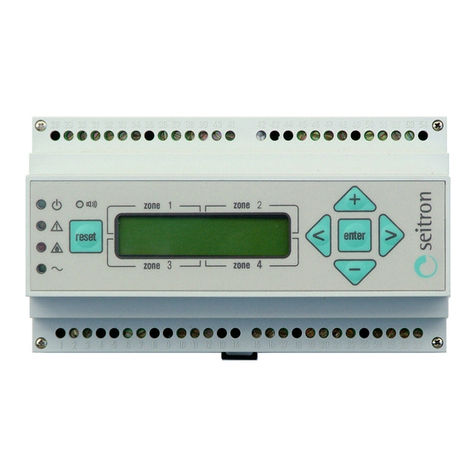
Seitron
Seitron RGY 000 MBP4 Operation, installation, and maintenance manual

Macurco
Macurco CM-E1 manual
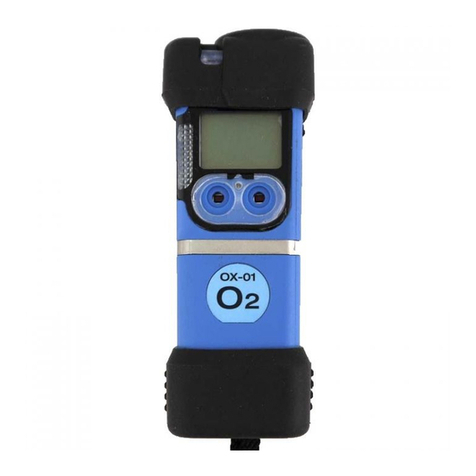
RKI Instruments
RKI Instruments CO-01 Operator's manual
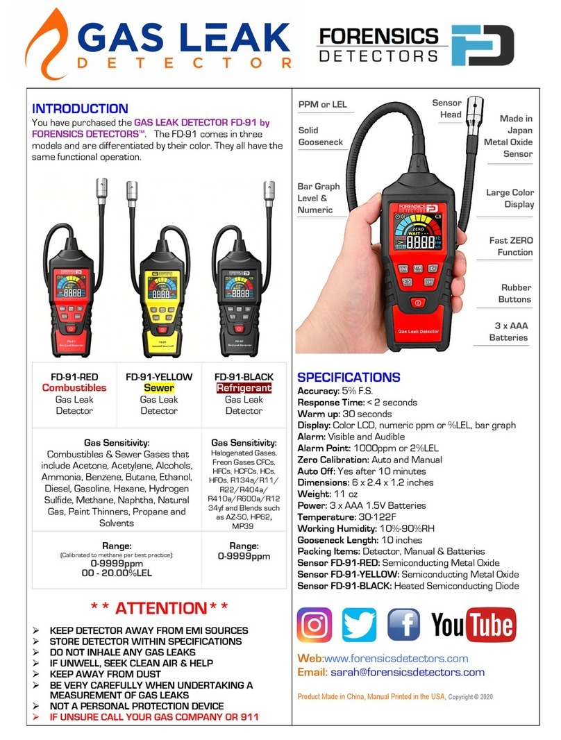
FORENSICS DETECTORS
FORENSICS DETECTORS FD-91 quick start guide

AGS
AGS Merlin Installation & operation instructions

BW Technologies
BW Technologies GasAlertClip Extreme instruction sheet

Riken Keiki
Riken Keiki GD-F3A-SC-A operating manual
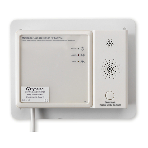
LEGRAND
LEGRAND Tynetec Aidcall ZXT486 instructions
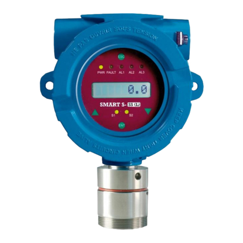
Sensitron
Sensitron SMART S Series Short installation manual
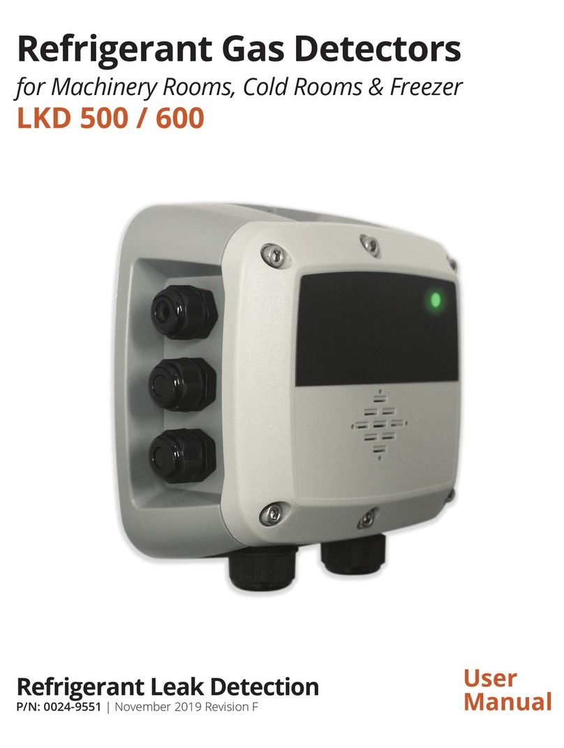
Elliwell
Elliwell LKD 500 user manual
