manuals.online logo
Brands
  1. Home
  2. •
  3. Brands
  4. •
  5. Sensitron
  6. •
  7. Gas Detector
  8. •
  9. Sensitron SMART S Series User manual

Sensitron SMART S Series User manual

Pag. 1
Manuale installazione rapido / Short installation manual
MT4962 rev.0 10/05/2021
SMART S
Manuale installazione rapido / Short installation manual
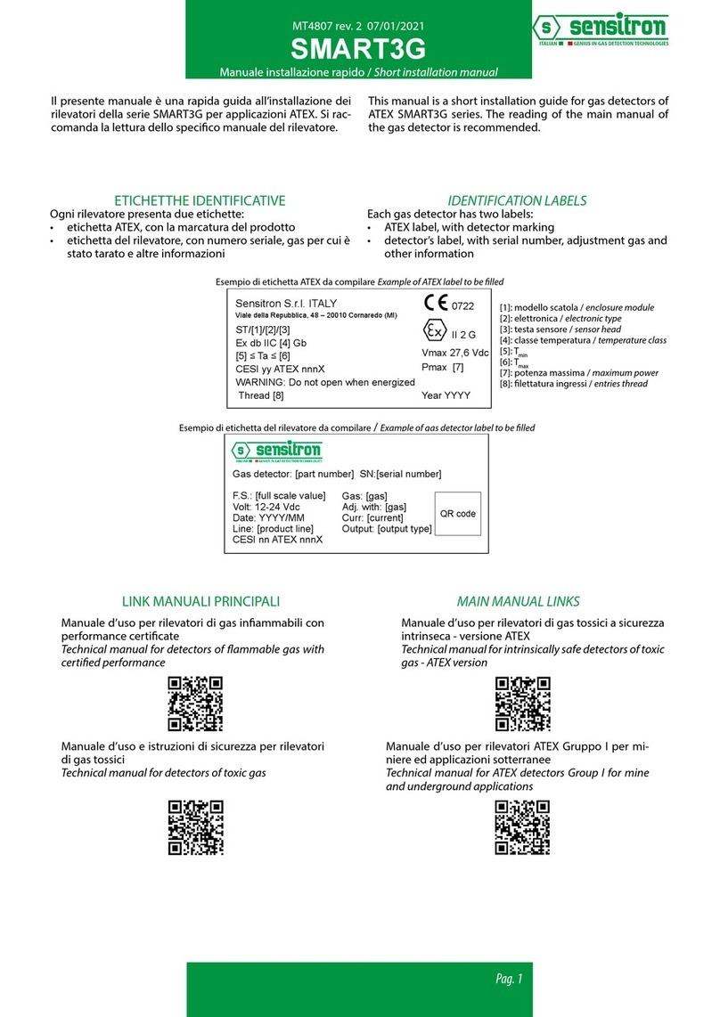
ETICHETTHE IDENTIFICATIVE IDENTIFICATION LABELS
LINK MANUALI PRINCIPALI
Manuale d’uso per rilevatori di gas inammabili con
performance certicate
Technical manual for detectors of ammable gas with
certied performance
Manuale d’uso e istruzioni di sicurezza per rilevatori
IECEx
Technical manual for IECEx gas detectors
Manuale d’uso per rilevatori per applicazioni nel set-
tore navale
Technical manual for detectors for marine environment
ST/*/*/N1; ST/*/*/N2; ST/*/*/N3; ST/*/*/S1; ST/*/*/S2; ST/*/*/S3;
ST/*/*/C1; ST/*/*/C2; ST/*/*/C3
ATEX marking and additional information label
The fields marked with [..] are compiled according to instructions on page 3.
ST/[1]/[2]/[3]
Ex db IIC [4] Gb
[5] ≤ Ta ≤ [6]
CESI yy ATEX nnnX
WARNING: Do not open when energized
Thread [8]
Label characteristics
Material: 3M 3812, 3M HiPerformance, Roll cover part number: 157001 or equivalent
Dimensions: 22 x 50 mm or bigger
0722
II 2 G
Vmax 27,6 Vdc
Pmax [7]
Year YYYY
Gas detector: [part number] SN:[serial number]
F.S.: [full scale value]
Volt: 12-24 Vdc
Date: YYYY/MM
Line: [product line]
CESI nn ATEX nnnX
Logo in colour or in
black and white
Sensitron S.r.l. ITALY
Viale della Repubblica, 48 – 20010 Cornaredo (MI)
Gas: [gas]
Adj. with: [gas]
Curr: [current]
Output: [output type]
QR code
Doc. number
MEEX3937
Page 1 of 4
Rev. Description Prepared by / Date Checked by / Date Approved by / Date
0ATEX marking details Å. Hellstrand 26/07/2017 Å. Hellstrand 26/07/2017 G. Frigo 26/07/2017
1Updated standard revision Å. Hellstrand 04/12/2019 Å. Hellstrand 04/12/2019 G. Frigo 04/12/2019
2Label revision S. Colombo 05/05/2020 S. Colombo 05/05/2020 G. Frigo 05/05/2020
[1]: modello scatola / enclosure module
[2]: elettronica / electronic type
[3]: testa sensore / sensor head
[4]: classe temperatura / temperature class
[5]: Tmin
[6]: Tmax
[7]: potenza massima / maximum power
[8]: lettatura ingressi / entries thread
Esempio di etichetta ATEX da compilare Example of ATEX label to be lled
Esempio di etichetta del rilevatore da compilare / Example of gas detector label to be lled
ST/*/*/N1; ST/*/*/N2; ST/*/*/N3; ST/*/*/S1; ST/*/*/S2; ST/*/*/S3;
ST/*/*/C1; ST/*/*/C2; ST/*/*/C3
ATEX marking and additional information label
The fields marked with [..] are compiled according to instructions on page 3.
ST/[1]/[2]/[3]
Ex db IIC [4] Gb
[5] ≤ Ta ≤ [6]
CESI yy ATEX nnnX
WARNING: Do not open when energized
Thread [8]
Label characteristics
Material: 3M 3812, 3M HiPerformance, Roll cover part number: 157001 or equivalent
Dimensions: 22 x 50 mm or bigger
0722
II 2 G
Vmax 27,6 Vdc
Pmax [7]
Year YYYY
Gas detector: [part number] SN:[serial number]
F.S.: [full scale value]
Volt: 12-24 Vdc
Date: YYYY/MM
Line: [product line]
CESI nn ATEX nnnX
Logo in colour or in
black and white
Sensitron S.r.l. ITALY
Viale della Repubblica, 48 – 20010 Cornaredo (MI)
Gas: [gas]
Adj. with: [gas]
Curr: [current]
Output: [output type]
QR code
Doc. number
MEEX3937
Page 1 of 4
Rev. Description Prepared by / Date Checked by / Date Approved by / Date
0ATEX marking details Å. Hellstrand 26/07/2017 Å. Hellstrand 26/07/2017 G. Frigo 26/07/2017
1Updated standard revision Å. Hellstrand 04/12/2019 Å. Hellstrand 04/12/2019 G. Frigo 04/12/2019
2Label revision S. Colombo 05/05/2020 S. Colombo 05/05/2020 G. Frigo 05/05/2020
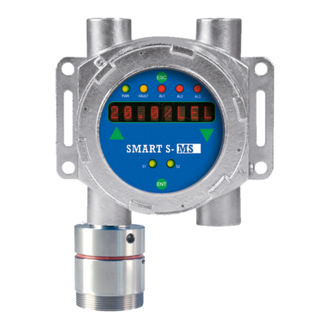
Il presente manuale è una rapida guida all’installazione dei
rilevatori della serie SMART S. Si raccomanda la lettura dello
specico manuale del rilevatore.
I rilevatori SMART S-SS sono provvisti di display, i rilevatori
SMART S-MS no; entrambi possono essere equipaggiati con
un’apposita scheda per la comunicazione HART.
Ogni rilevatore presenta due etichette:
• etichetta ATEX, con la marcatura del prodotto
• etichetta del rilevatore, con numero seriale, gas per cui è
stato tarato e altre informazioni
MAIN MANUAL LINKS
This manual is a short installation guide for gas detectors of
SMART S series. The reading of the main manual of the gas
detector is recommended.
SMART S-SS gas detectors are equipped with a display bo-
ard, while SMART S-MS not. Both can be equipped with a
board fot HART communication.
Each gas detector has two labels:
• ATEX label, with detector marking
• detector’s label, with serial number, adjustment gas and
other information
Manuale d’uso per rilevatori di gas tossici
Technical manual for detectors of toxic gas
Pag. 2
Manuale installazione rapido / Short installation manual
MT4962 rev.0 10/05/2021
SMART S
Durante le operazioni di montaggio e installazione, gli im-
pianti devono essere messi in sicurezza. Inoltre è opportuno
tenere in considerazione alcune norme generali, quali:
• Si raccomanda di non installare rivelatori gas nelle vici-
nanze di prese d’aria e/o ventilatori che provocano forti
correnti d’aria.
• I rivelatori non devono essere altresì posti in zone nel-
le quali siano presenti vibrazioni e, sebbene immuni da
disturbi a radiofrequenze è consigliabile non installarle
in prossimità di emettitori radio (ponti radio o apparec-
chiature simili).
• Altra buona norma è quella di installare il rivelatore in
zone facilmente accessibili per le operazioni di test e ta-
ratura e per l’inserimento dell’adattatore del kit di cali-
brazione.
• I gas più leggeri dell’aria (Metano, Idrogeno, Ammonia-
ca), disperdendosi nell’ambiente, tenderanno a salire
verso l'alto; per ottenere un ecace intervento il rivela-
tore deve essere posizionato a 30 cm dal sotto.
• I gas più pesanti dell’aria (GPL, Butano, Vapori Benzina)
disperdendosi stazioneranno nella parte bassa dell’am-
biente; il rivelatore deve quindi essere posizionato a 30
cm dal pavimento.
PREDISPOSIZIONE SITO DI INSTALLAZIONE
INSTALLAZIONE
Modalità per il corretto montaggio:
Il rivelatore deve sempre essere installato con l’elemento
sensibile (testa di rivelazione) rivolta verso il basso. Il conte-
nitore del rivelatore per nessuna ragione deve essere forato;
per il ssaggio utilizzare i fori già esistenti.
I rivelatori con protezione Exd sono forniti completi di staa
per ssaggio a muro.
LINK MANUALI ACCESSORI
Scheda display
Display board
Scheda 3 relè
3 relays board
Tastierino di calibrazione
Calibration keypad
INSTALLATION SITE PREARRANGEMENT
INSTALLATION
At the mounting and installation phase be sure all safety
precautions have been considered. Always consider how im-
portant it is the correct positioning of gas detectors to get
the optimum response.
• Be careful never to install gas detectors close to air inta-
kes or fans causing strong air currents.
• Be sure the detectors are attached to a rm base to pre-
vent vibration that can damage them, producing unreli-
able results.
• Although the electronics comply with the electromag-
netic compatibility rules, it is advised to keep the detec-
tors at a distance from any radio frequency senders (such
as radio links or similar).
• Please be also sure that detectors are placed in a con-
venient location for future maintenance and calibration
requirements.
• All of the gases lighter than air (Methane, Hydrogen, Am-
monia) tend to spread upwards; the detector should be
placed at 30 cm from the ceiling in order to maximise the
eectiveness of the detection.
• All of the gases heavier than air (LPG, Butane, Petrol Va-
pours) tend to spread downwards; the detector should
be placed at 30 cm from the oor.
Correct positioning mode:
The gas detector is always to be mounted with the sensing
element placed downward.
For no reasons at all the enclosure can be drilled.
Wall mount the detectors by employing the existing holes.
Exd detectors come complete with wall xing brackets.
Display LED Display OLED
Kit testa remota (5 m)
Remote head kit (5 m)
Kit testa remota (25 m)
Remote head kit (25 m)
ACCESSORIES MANUAL LINKS
Kit di calibrazione
Calibration kit
Modulo HART
HART module
Pag. 3
Manuale installazione rapido / Short installation manual
MT4962 rev.0 10/05/2021
SMART S
Schema topograco del circuito senza modulo HART: Detector circuit layout without HART module:
Connessione scheda display
(per rilevatori SMART S-SS)
Display board connection
(SMART S-SS gas detectors)
JP10
DL1
DL2
DL3
JP1
456
JP3
JP6
JP5
123
LED DL2 (verde / green)
descrive lo stato del rilevatore
indicates the detector working condition
LED DL3 (Rosso / Red)
Stato del Watch-Dog esterno:
- Funzionamento normale: LED spento
- Danno: LED acceso
LED DL1 (rosso / red)
RS485 monitoraggio TX:
Lampeggia quando si stanno trasferendo dei dati
Collegamento testa sensore
Connection sensor head
JP6:
Connessione scheda relè o tastierino di calibrazione
Relay board or calibration keypad connection
JP3: Resistenza di fine linea RS485
Chiuso: resistenza da 120 ohm inserita
Aperto: resistenza da 120 ohm non inserita
-Vcc 12-24V
+Vcc 12-24V
RS485: A
RS485: B
4-20 mA
Not usato / Not used
External Watch-Dog status:
- Normal operation mode: LED Off
- Failure: LED on
JP3: RS485 end of line resistor
Closed: 120 ohm resistor connected
Open: 120 ohm resistor not connected
1
1
1
1
2
2
3
3
4
4
5
5
6
6
JP1
+Vcc 12-24V
-Vcc 12-24V
RS485 - A
RS485 - B
Segnale 4-20mA
di comunicazione HAR
T
JP4
1
6
JP6
JP5
JPS2 JPS3
JPC3 JPC2 JPC1
JPP1
S1
JPS2:
Selezione per l’attivazione del relè 2
Selection of activation event for relay 2
JPS3:
Selezione per l’attivazione del relè 3
Selection of activation event for relay 3
+
-
1-2 : Relè 1 / Relay 1
3-4 : Relè 2 / Relay 2
5-5 : Relè 3 / Relay 3
DLB1, DLB2, DLB3 :stato relè / relay status
JPP1:
Modalità di settaggio per i 3 relè
Global Operation Mode Setting of 3 Relays
JP5 :
Connettore per tastierino di calibrazione
Calibration keypad connection
H
K
S1 : Spostare S1 verso il lato H per il normale funzionamento
con il modulo HART
S1 : Set S1 toward H side for normal working with HART connection
S1 : Spostare S1 verso il lato K per abilitare l’uso del tastierino
di calibrazione
S1 : Set S1 toward K side for calibration with keypad
1 2 3 1 2 3
JP6 : connettore per cavo flat
da modulo HART
connector for flat cable
from HART module board
DLB3 DLB2 DLB1
1
32 1
1 1
2345
JP4: contatti relè / relays contacts
JPC1, JPC2, JPC3:
Selezione contatto NO/NC sui 3 relè
Setting of NO/NC contact of 3 relays
Schema topograco del circuito con modulo HART: Detector circuit layout equipped with HART module:
• Relè 1 non programmabile e associato al FAULT e allo sta-
to del watchdog esterno.
• Relè 2 e 3 sono programmabili, di default sono associati
agli allarmi 2 e 3.
• Tutti i relè di default hanno i contatti normalmente chiusi
(NC) e sono impostati come normalmente energizzati.
• Relay 1 is not programmable and it associated to FAULT
and external watchdog status.
• Relays 2 and 3 are programmable, as default they are as-
sociated to alarm 2 and 3.
• Alla relays as default condition have the contacts normal-
ly closed (NC) and they are set as normally energized.
Pag. 4
Manuale installazione rapido / Short installation manual
MT4962 rev.0 10/05/2021
SMART S
Contact details: SENSITRON s.r.l. Viale della Repubblica, 48 - 20007 - Cornaredo (MI) Italy
TEL. +39 0293548155 - FAX +39 0293548089 - www.sensitron.it - E-mail: sales@sensitron.it
LEADER IN SIL2 (SIL3) FIXED GAS DETECTION SYSTEMS
Accensione
Al momento in cui il rivelatore viene alimentato, si accende
ad intermittenza lenta il LED verde sulla scheda base. L’uscita
in corrente è 2 mA circa.
Trascorsi 2 minuti e terminata la fase di warm-up, l’uscita in
corrente passa a 4,0 mA.
Terminata la fase di preriscaldamento il rivelatore è in grado
di funzionare correttamente, anche se sono comunque ne-
cessarie 2 ore circa anché il rilevatore raggiunga le presta-
zioni ottimali.
Se il rivelatore è provvisto di scheda display, consultare il
manuale aggiuntivo MT3771.
Collaudo
Il rilevatore viene tarato in fabbrica per il gas specicamente
richiesto dal cliente. Successivamente è possibile controllare
e eventualmente correggerne la taratura utilizzando l’appo-
sita tastiera di calibrazione.
Vericare la risposta del rivelatore utilizzando una miscela a
composizione nota gas/aria, e l'apposito KIT di taratura.
Uso
Il rivelatore funziona automaticamente e autonomamente,
pertanto non è richiesto alcun contributo da parte del suo
utilizzatore.
Il LED verde lampeggiante posto sulla scheda base del circu-
ito indica lo stato in cui il rilevatore si trova.
COLLAUDO E USO
MANUTENZIONE
Nei paesi della Comunità Europea, le prove di funzionamen-
to in gas e le procedure di taratura dei rivelatori di gas sono
richieste dalle normative in vigore e deniti dalla EN 60079-
29-2.
Questa norma fornisce una guida alla scelta, installazione,
uso e manutenzione dei sistemi di rivelazione gas destinati
ad uso industriale e civile.
Secondo questa direttiva, tutti i rivelatori di gas devono
essere controllati secondo le indicazioni fornite dal fabbri-
cante annotando su apposito registro i risultati delle prove
eettuate. Tale registro deve rimanere a disposizione delle
autorità competenti in caso di controlli.
TESTING AND USE
MAINTENANCE
Power ON
When the detector is powered on, the green LED on the
motherboard starts blinking at slow intermittent. Output
current is nearly 2 mA.
After 2 minutes and nished the warmup step, the output
current is 4.0mA.
Once the warm-up phase is over, the detector can work cor-
rectly, although the optimal performances will be achieved
after two hours.
Should the detector be provided with display, please refer to
the additional technical handbook MT3771.
Testing
Detectors are factory calibrated for the specic gas required
by the customers. Future adjustment of the preset calibra-
tion can be carried out by employing the calibration keypad.
Testing should be carried out by using a gas mixture in the
appropriate range, along with our calibration kit.
Use
The detector works autonomously and automatically. Once
adequately connected, no further operations are required.
The ashing green LED on the motherboard indicates the
detector's working condition as detailed in the main man-
ual.
Within the European Union Countries, bump testing and
calibration procedures of gas detectors are required by strict
regulations and detailed in the IEC EN 60079-29-2.
This norm gives guidance on the selection, installation, use
and maintenance of gas detectors intended for use in indus-
trial and commercial applications.
The standard requires calibration and bump testing as well
as recording of the performed checks and it denes that all
gas detectors should undergo periodical operational testing
according to the manufacturer’s specications. Test results
should be recorded into a suitable book to be shown to the
Authority in case of inspection.
Sensitron srl lavora per un costante miglioramento dei propri prodotti e si riserva di variarne le ca-
ratteristiche tecniche senza preavviso. Per avere le caratteristiche dei prodotti aggiornate vericare
sul sito www.sensitron.it oppure scrivere a [email protected]
Sensitron srl works for a constant improvement of its products and reserves the right to change the
technical data without notice. To have the updated product characteristics check on the website www.
sensitron.it or write an e-mail to [email protected]

Other manuals for SMART S Series

1

Other Sensitron Gas Detector manuals

Sensitron SMART3 NC User manual

Sensitron

Sensitron SMART3 NC User manual

Sensitron SMART3H LITE User manual

Sensitron

Sensitron SMART3H LITE User manual

Sensitron HART User manual

Sensitron

Sensitron HART User manual

Sensitron SMART3G User manual

Sensitron

Sensitron SMART3G User manual

Sensitron SMART 3 User manual

Sensitron

Sensitron SMART 3 User manual

Sensitron SMART3R LITE User manual

Sensitron

Sensitron SMART3R LITE User manual

Sensitron P User manual

Sensitron

Sensitron P User manual

Sensitron SMART3-R Series User manual

Sensitron

Sensitron SMART3-R Series User manual

Sensitron SMART S Series Instruction Manual

Sensitron

Sensitron SMART S Series Instruction Manual

Sensitron SMART3G User manual

Sensitron

Sensitron SMART3G User manual

Sensitron SMART3G Installation and operating instructions

Sensitron

Sensitron SMART3G Installation and operating instructions

Sensitron SMART 3 User manual

Sensitron

Sensitron SMART 3 User manual

Sensitron MULTISCAN++/S1-32B Guide

Sensitron

Sensitron MULTISCAN++/S1-32B Guide

Sensitron SMART3G User manual

Sensitron

Sensitron SMART3G User manual

Sensitron LCR2 Series User manual

Sensitron

Sensitron LCR2 Series User manual

Sensitron SMART P User manual

Sensitron

Sensitron SMART P User manual

Sensitron PL4 +D Reference manual

Sensitron

Sensitron PL4 +D Reference manual

Sensitron SMART S-IS User manual

Sensitron

Sensitron SMART S-IS User manual

Sensitron Multiscan++PK32 Guide

Sensitron

Sensitron Multiscan++PK32 Guide

Sensitron GAS TEST KIT User manual

Sensitron

Sensitron GAS TEST KIT User manual

Sensitron SMART3G-GrI User manual

Sensitron

Sensitron SMART3G-GrI User manual

Sensitron SMART S User manual

Sensitron

Sensitron SMART S User manual

Sensitron SMART3H LITE User manual

Sensitron

Sensitron SMART3H LITE User manual

Sensitron PATROL User manual

Sensitron

Sensitron PATROL User manual

Popular Gas Detector manuals by other brands

Macurco DMK-1 Installation and operation instructions

Macurco

Macurco DMK-1 Installation and operation instructions

TELEDYNE OLDHAM SIMTRONICS CTX 300 user manual

TELEDYNE OLDHAM SIMTRONICS

TELEDYNE OLDHAM SIMTRONICS CTX 300 user manual

AKO AKO-522014 manual

AKO

AKO AKO-522014 manual

GMI Gasurveyor 11-500 User handbook

GMI

GMI Gasurveyor 11-500 User handbook

Dräger X-am 5800 Instructions for use

Dräger

Dräger X-am 5800 Instructions for use

BEINAT SG800 manual

BEINAT

BEINAT SG800 manual

Axetris LGD F200P2 Operation and integration instructions

Axetris

Axetris LGD F200P2 Operation and integration instructions

Dräger X-am 2800 Instructions for use

Dräger

Dräger X-am 2800 Instructions for use

LEGRAND 6827 00 quick start guide

LEGRAND

LEGRAND 6827 00 quick start guide

GasDog GD400 Series user manual

GasDog

GasDog GD400 Series user manual

MSA S5000 operating manual

MSA

MSA S5000 operating manual

GasDog GD-600 user manual

GasDog

GasDog GD-600 user manual

ISC GasBadge Plus 3.0 manual

ISC

ISC GasBadge Plus 3.0 manual

AccuTools eL-720 user guide

AccuTools

AccuTools eL-720 user guide

Riken Keiki RI-2000R operating manual

Riken Keiki

Riken Keiki RI-2000R operating manual

Brandson Equipment 304339 user manual

Brandson Equipment

Brandson Equipment 304339 user manual

SENSIT Technologies IRED instruction manual

SENSIT Technologies

SENSIT Technologies IRED instruction manual

Honeywell Sensepoint XCL quick start guide

Honeywell

Honeywell Sensepoint XCL quick start guide

manuals.online logo
manuals.online logoBrands
  • About & Mission
  • Contact us
  • Privacy Policy
  • Terms and Conditions

Copyright 2025 Manuals.Online. All Rights Reserved.