International Harvester Company BD-144 Series User manual

n
INTERNATIONAL
BD-144,BD-154Series
DIESEL ENGINES
and
BC-144Series
PETROL ENGINES
SM-12A
INTERNATIONAL HARVESTERCOMPANYof GREAT BRITAIN LIMITED
P.O.BOX25 259 CITY ROAD LONDON ECIP1AD KBB/4/78 MeC

•
•
•
i
~
.'

SM-11A
SERVICE MANUAL
INTERNATIONAL
BC-144 BD-144
&
BD-154
SERIES ENGINES
The black tabs shown on the right-hand side of this page
line up with the corresponding tabs on the index pages
of the respective groups.
NOTE
Refer to the SUPPLEMENT AND CHANGE INDEX for a list
of supplements. and to the end of the appropriate group for
the latest instructions. before carrying out work on this equip-
ment.
INTERNATIONAL HARVESTERCOMPANY
OF GREAT BRITAIN LIMITED
PO BOX 25, 259 CITY ROAD, LONDON EC1P lAD
GENERAL
MANIFOLDS.
CYliNDER HEAD
AND VALVES
CONNECTING RODS.
PISTONS AND
CYLINDER SLEEVES
LUBRICATION
SYSTEM
COOLING
SYSTEM
TIMING GEAR TRAIN.
FRONT COVER
AND CAMSHAFT
CRANKSHAFT •
MAIN BEARINGS
AND FLYWHEEL
GOVERNOR
BC -144 ENGINE
CARBURETTOR
Be -144 ENGINE
LPG ATTACHMENT
BC-144 ENGINE

r---------
•
•
•
•
•

INTERNATIONAL
8C-144, 80-144
&
80-164
SERIES ENGINES
GROUP 1
GENERAL

1- 1
1. INTRODUCTION
1a. GENERAL
The instructions contained in this
service m an u a l are for the information
and guidance of servicemen who are
responsible for overhauling and re-
pairing International BD-144 and
BD-154 diesel engines, and BC-144
petrol engines.
, b, SERVICETOOLS
International engines are designed
so that few special tools are required.
However. whenever the use of inexpen-
sive special service equipment will
facilitate work. such equipment is
mentioned in this manual. Where
this equipment can easily be made
in the workshop. dimensional draw-
ings have been provided.
1c. SERVICEPARTS
I.
H. engines deserve genuine
I.
H.
service parts. The best material ob-
tainable and experience gained
through many years of construction
and farm equipment manufacturing
enable the International Harvester
company to produce quality that will
not be found in imitation or "just as
good" repair parts. No serviceman
can afford to guarantee a repair job
that has not been serviced with gen-
uine
I.
H. parts. For the correct
service parts to be used always refer
to the Parts Catalogue. The loose-
leat catalogues are accurate and are
brought up to date continually by
issuing revisions.
td. SERIAL·NUMBERS
The engine serial number is stamped
on a pad on the R. H. side of the
crankcase.
1e. DIESELFUEL INJECTION EQUIPMENT
If detailed information on the fuel
injection equipment and fuel
lift
pump is desired. refer to the"FUEL
II
INJECTION SERVICE MANUAL SM-ll.
1f.
ELECTRICAL
u
Full details of servlclng and adjust-
ing the electrical equipment will be
found in the "ELECTRICAL EQUIPMENT
SERVICE MANUAL SM-14",
1
g.
ADJUSTMENTS
Where adjustments are necessary
the group will contain the relevant
information. Reference to that sec-
tion before commencing to dismantle
the unit may prevent unnecessary
work being carried out.
1h. ILLUSTRATIONS
Four types of illustration references
will be found in this-manual and
these are explained by the following
examples:
(a) (1-4) This refers to the item
marked by indicator number 1 in
FIGURE 4 of the GROUP in which the
re ference appears.
(b) (1
&
2-4) This refers to the
items marked by indicator numbers
i
and 2 in FIGURE 4 of the GROUP
in which the reference appears.
(c) (1-4
&
2-6) This refers to items
marked by indicator number 1 in
FIGURE 4 and indicator number 2 in
FIGURE 6 of the GROUP in which the
reference appears.
(d) (1-4 GROUP 5) This is used
when reference is made to an illust-
tration in another GROUP, A GROUP
number may be used in conjunction
with (a). (b). or(c)toshowthe
indicator number. FIGURE number
and GROUP in which the illustration
appears,
1
i.
INSPECTIONAND REPAIR
The fo
Ll
o
w
Lng
notes should be used
as a general g u
i
d e to inspection and
repair. Where a special procedure is
necessary for a component or assembly.
full details w ill be found in the
relevant section of the group,
(a) BEARINGS
Inspect for evidence of overheat-
ing. cracks. scores. pitting and
general wear. Replace if necessary.
Soak in oil. wrap or cover until ready
for assembly.
(b) PINS AND BUSHES
Inspect for damage. scoring and
pitting. Check with mating parts for
wear.
(c) GASKETS AND SEALS
Always use new gaskets and seals
during assembly. Be extremely care-
ful not to damage the seal or ga-sket
during installation. pack lip type
seals with grease and use sleeves where-
ever a seal has to be passed over
splines or threads.
(d) GEARS AND SPLINES
Check for cracks. pitting. burrs.
broken or missing teeth. Check for
excessive wear with mating parts.
Remove burrs c a r e fu l l
y •
DO NOT
interfere with tooth or spline profile.
REPLACE all parts which show damage
or excessive wear.
(e) WELDS
Check all welded assemblies for
cracks. tWisting and misalignment.
Information concerning the use of
special welding rods or welding pro-
cedure is detailed. where relevant.
in the appropriate section of the
group.
(f)
CASTINGS
Check castings for cracks and dis-
tortion.
(g) FUEL. OIL AND COOLANT PIPES
AND HOSES
Check unions for leaks. stripped
threads or other faults. Check pipes
for cracks or chafing. hoses for
chafing. twisting. perishing or other
damage.
2 ·1
(h) LUBRICATION FITTINGS
Check for damaged or missing
fittings and replace. Check that
grease and oil galleries are clear.
1j. LUBRICATION
When assembling any part. always
coat all wearing surfaces with the
lubricant specified in the operator's
manual. Use sufficient quantities of
lubricant to prevent any danger of
se
i
z
i
n g , scoring or excessive wear
when the assembly is first operated.
FAILURE TO PROVIDE "STARTING
LUBRICATION" MAY RESULT IN
SERIOUS DAMAGE.
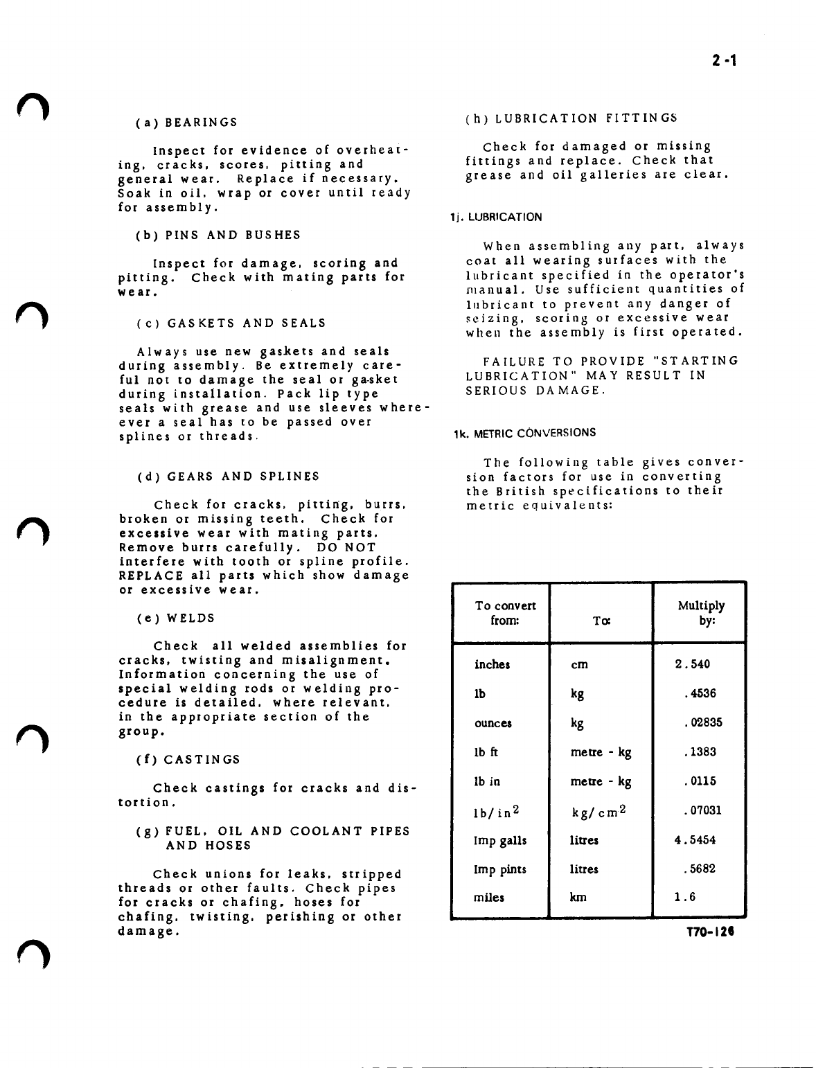
1k. METRICCONVERSIONS
The following table gives conver-
sion factors for use in converting
the British specifications to their
metric equivalents:
To convert Multiply
from: To: by:
inches cm 2.540
Ib kg .4536
ounces kg .02835
lb
ft
metre - kg .1383
lb in metre - kg .0115
Ib/in2 kg/ cm2 .07031
Imp gaUs litres 4.5454
Imp pints litres .5682
miles km 1.6
T70-12I
3-'
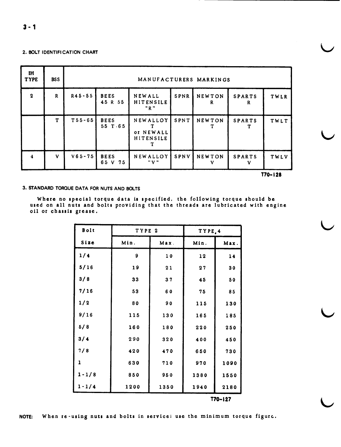
2. BOLT IDENTIFICATION CHART
IH
TYPE BSS MAN UF ACTURERS MARKIN GS
2 R R45-55 BEES NEWALL SPNR NEWTON SPARTS TWLR
45 R 55 HIT ENSILE RR
"R"
TT55-65 BEES NEWALLOY SPNT NEWTON SPARTS TWLT
55 T· 65 T TT
or NEWALL
HITENSILE
T
4VV65-75 BEES NEW ALLOY SPNV NEWTON SPARTS TWLV
65 V 75
"V"
VV
T70-128
3. STANDARD TORQUEDATA FORNUTSAND BOLTS
Where no special torque data
is
specified. the following torque should be
used on all nuts and bolts providing that the threads are lubricated with engine
oil or challis grease.
Bolt TYPE 2 TYPE,4
SIze Min. Max. MIn. Max.
1/4 910 12
14
5/16 19 21 27 30
3/8 33 37 45 50
7/16 53 60 75 85
1/2 80 90 115 130
9/16 115 130 165 185
5/8 160 180 220 250
3/4 290 320 400 450
7/8 420 470 650 730
1630 710 970 1090
1-1/8 850 950 1380 1550
1-1/4 1200 1350 1940 2180
T70-127
NOTE: When r e - u s
t
n gnu
ts
and bolt sin se r vic e
i
ulet hem In imum tor que fig ur(..•
4-1
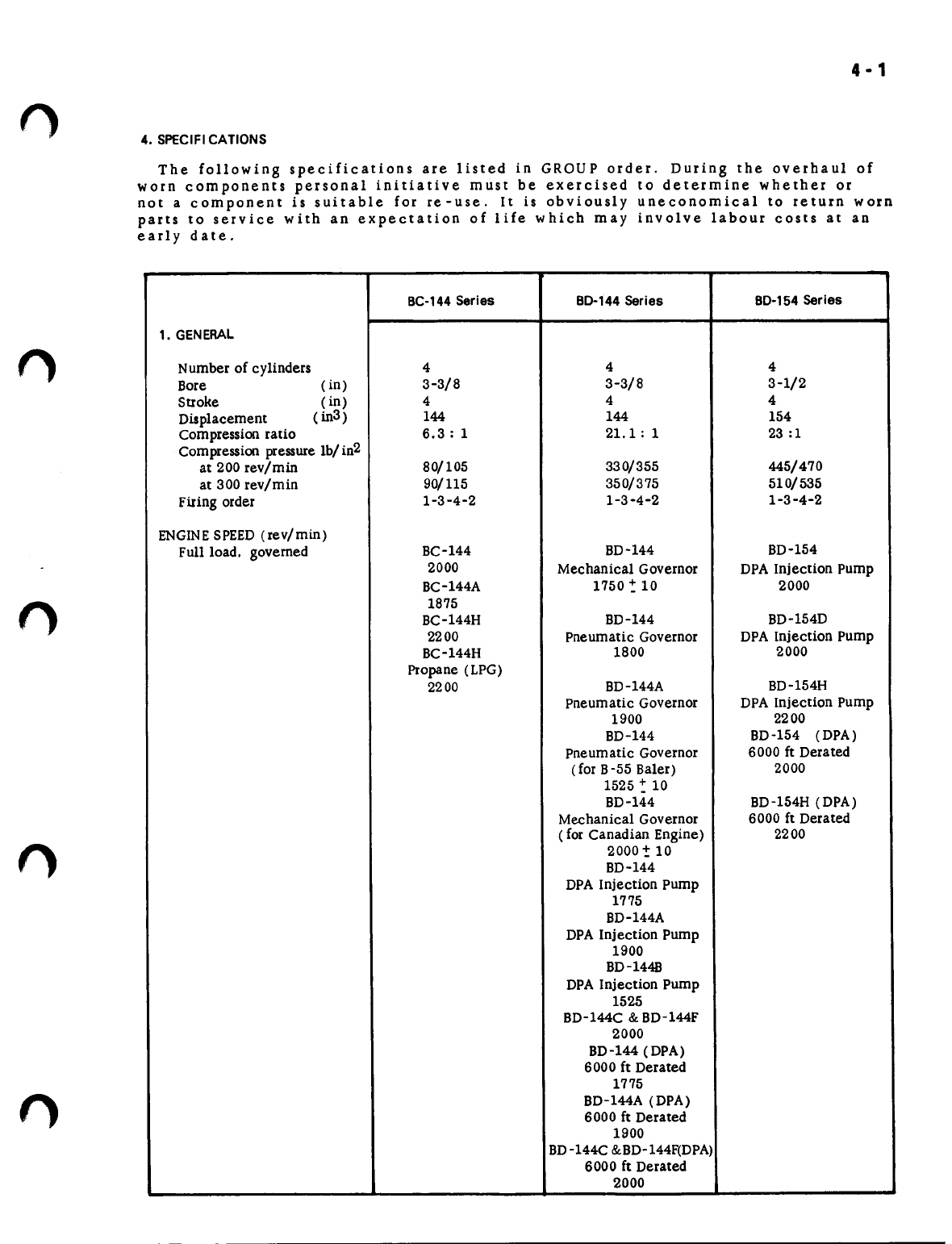
4. SPECIFICATIONS
The following specifications are listed in GROUP order. During the overhaul of
worn components personal initiative must be exercised to determine whether or
not a component is suitable for re-use. It is obviously uneconomical to return worn
parts to service with an expectation of life which may involve labour costs at an
early date.
BC-144 Series BO-144 Series BO-154 Series
1. GENERAL
Number of cylinders 444
Bore (in) 3-3/8 3-3/8 3-1/2
Stroke (in) 4 4 4
Displacement (in3 ) 144 144 154
Compression ratio 6.3: 1 21.1: 1 23 :1
Compression pressure lb/ in2
at 200 rev/min 80/105 330/355 445/470
at 300 rev/min 90/115 350/375 510/535
Firing order 1-3-4-2 1-3-4-2 1-3-4-2
ENGINESPEED (rev/min)
Full load. governed BC-144 BD-144 BD-154
2000 Mechanical Governor DPA Injection Pump
BC-144A 1750 -: 10 2000
1875
BC-144H BD-144 BD-154D
2200 Pneumatic Governor DPA Injection Pump
BC-144H 1800 2000
Propane (LPG)
2200 BD-144A BD-154H
Pneumatic Governor DPA Injection Pump
1900 2200
BD-144 BD-154 (DPA)
Pneumatic Governor 6000 ft Derated
(for B-55 Baler) 2000
1525 -: 10
BD-144 BD-154H (DPA)
Mechanical Governor 6000 ft Derated
( for Canadian Engine) 2200
2000 ~ 10
BD-144
DPA Injection Pump
1775
BD-144A
DPA Injection Pump
1900
BD-1448
DPA Injection Pump
1525
BD-l44C & BD-l44F
2000
BD-l44 (DPA)
6000 ft Derated
1775
BD-l44A (DPA)
6000 ft Derated
1900
BD-144C &BD-144F(DPA)
6000 ft Derated
2000
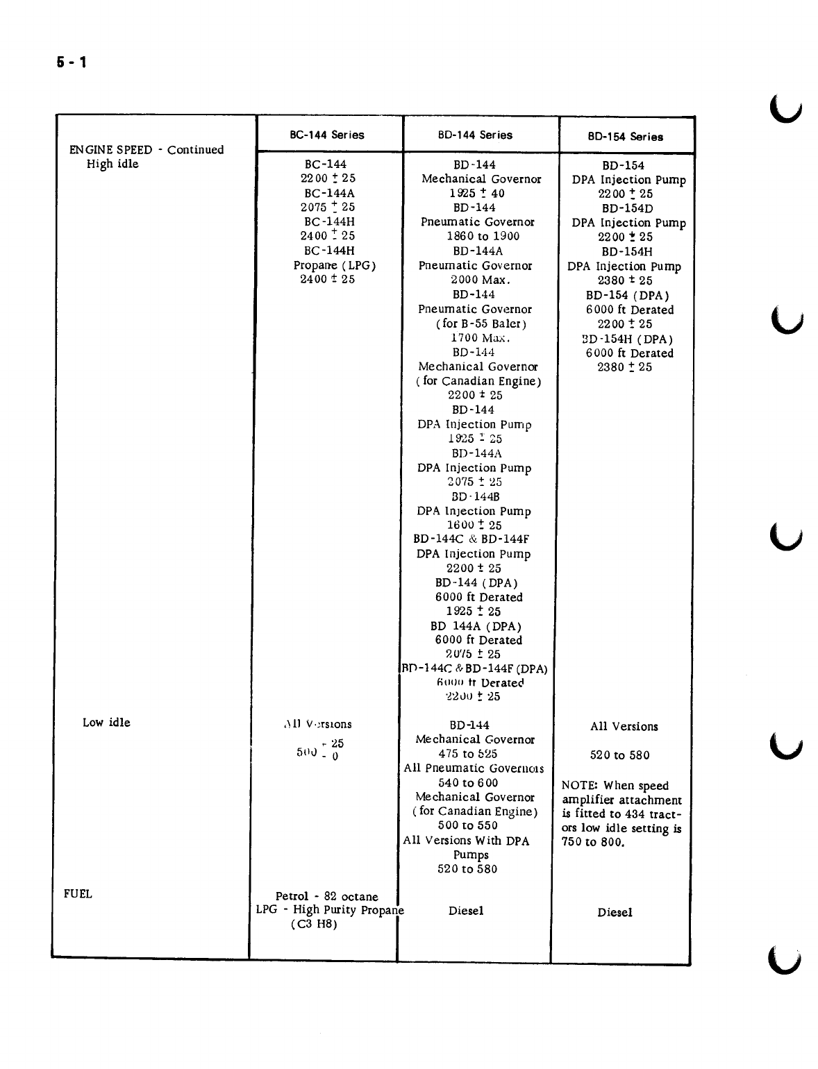
6 - 1
BC-144Series 80-144 Series 80-154 Series
ENGINESPEED - Continued
High idle BC-144 BD-144 BD-154
2200 -:25 Mechanical Governor DPA Injection Pump
BC-144A 1925:- 40 2200:25
2075 ~ 25 BD-144 BD-154D
BC-144H Pneumatic Governor DPA Injection Pump
2400: 25 1860 to 1900 2200
!
25
BC-l44H BD-144A BD-154H
Propane (LPG) Pneumatic Governor DPA Injection Pump
2400
±
25 2000 Max. 2380
t
25
BD-144 BD-154 (DPA)
Pneumatic Govemor 6000 ft Derated
(for B-55 Baler) 2200! 25
1700 Max. 3D-154H (DPA)
BD-V14 6000 ft Derated
Mechanical Governor 2380 -: 25
( for Canadian Engine)
2200
t
25
BD-144
DPA Injection Pump
19'25 :: 25
BD-1441\
DPA Injection Pump
2075
t
~5
3D-144B
DPA Injection Pump
1600! 25
BD-144C
&.
BD-144F
DPA Injection Pump
2200
t
25
BD-144 (DPA)
6000 ft Derated
1925
!
25
BD 144A (DPA)
6000 ft Derated
?'U'/5
±
25
flD-144C R>-BD-144F(DPA)
nlH)l1
tr Derate"
-~~VIJ ~
25
Low idle
,H1
V,:rSlOns BD-144 All Versions
- 25 Mechanical Governor
5(11) _ 0475 to 025 520 to 580
All Pneumatic Governors
540t0600 NOTE: When speed
Mechanical Governor amplifier attachment
( for Canadian Engine) is fitted to 434 tract-
500 to 550 ors low idle setting is
All Versions With DPA 750 to 800.
Pumps
520 to 580
FUEL Petrol - 82 octane
LPG - High Purity Propane Diesel Diesel
(C3 H8)
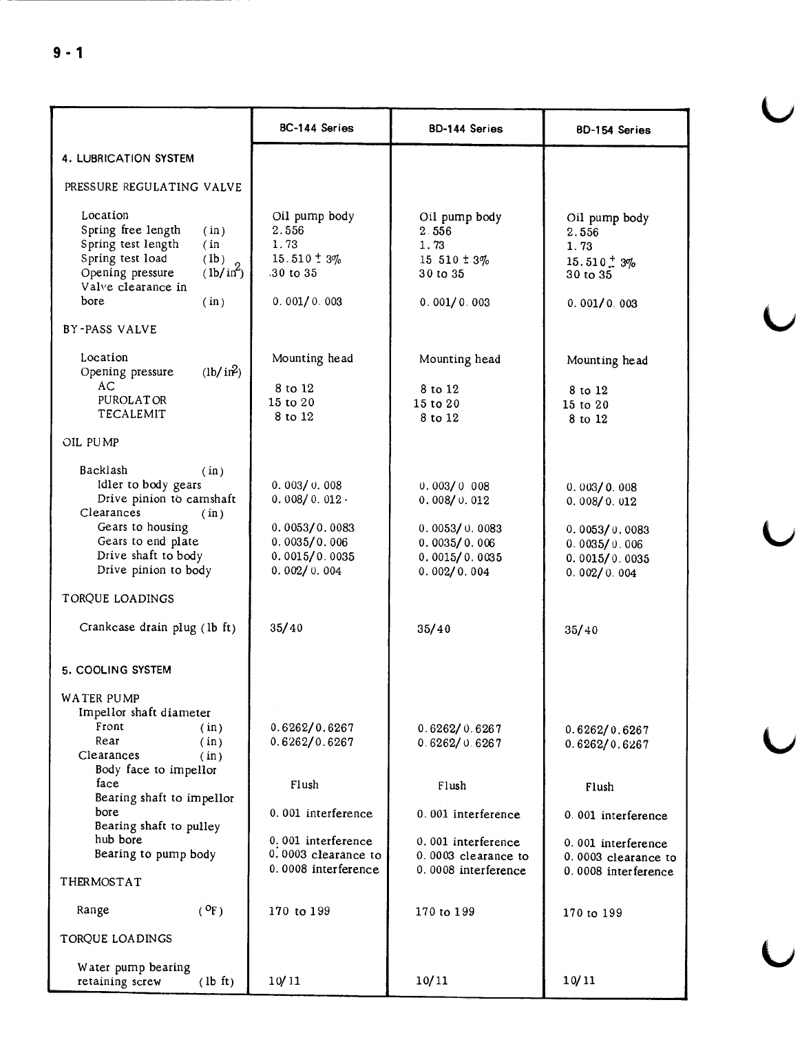
6 - 1
()
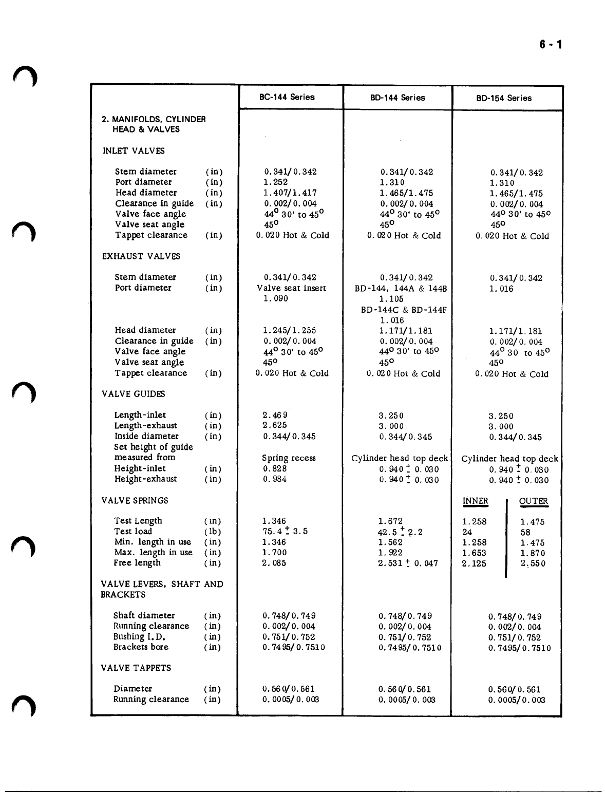
BC-144Series BD-144Series BD-154Series
2. MANIFOLDS.CYLINDER
HEAD
8t
VALVES
INLETVALVES
Stem diameter (in) 0.341/
O.
342 0.341/
O.
342 0.341/ 0.342
Port diameter (in) 1. 252 1.310 1.310
Head diameter (in) 1. 407/1. 417 1. 465/1. 475 1. 465/1. 475
Clearance
in
guide (in) 0.002/0.004 0.002/ 0.004 0.002/ 0.004
Valve face angle 44° 30' to 45° 44° 30' to 45° 440 3
O'
to 450
Valve seat angle 45° 45° 450
Tappet clearance (in) 0.020 Hot
&
Cold 0.020 Hot
&
Cold 0.020 Hot
&
Cold
EXHAUSTVALVES
Stem diameter (in) 0.341/
O.
342 0.341/
O.
342 0.341/ 0.342
Port diameter (in) Valve seat insert BD-l44. 144A
&
144B 1.016
1. 090 1.105
BD-144C
&
BD-144F
1.016
Head diameter (in) 1. 245/1. 255 1. 171/1. 181 1. 171/1. 181
Clearance in guide
(in)
O.
002/0.004 0.002/0.004
O.
002/
O.
004
Valve face angle 44° 30' to 45° 44°30' to 450 44°30 t045°
Valve seat angle 45° 45° 450
Tappet clearance
(in)
0.020 Hot
&
Cold 0.020 Hot
&
Cold 0.020 Hot
&.
Cold
VALVEGUIDES
Length-inlet
(in)
2.469 3.250 3.250
Length-exhaust (in) 2.62.5 3.000 3.000
Inside diameter (in) 0.344/
O.
345 0.344/
O.
345 0.344/
O.
345
Set height of guide
measured from Spring recess Cylinder head top deck Cylinder head top deck
Height-inlet
(in)
0.828
O.
940 ~ 0.030
O.
940 ~ 0.030
Height-exha ust (in) 0.984
O.
940 ~ 0.030
O.
940 ~ 0.030
VALVESPRINGS INNER OUTER
--
Test Length (in) 1.346 1.672 1.258 1.475
Test load
(lb)
75.4~3.5 42.5 -: ~. 2 24 58
Min. length in use (in) 1.346 1. 562 1.258 1.475
Max. length in use (in) 1.700 1. 922 1.653 1. 870
Free length (in) 2.085 2. 531 ~ 0.047 2.125 2,550
VALVELEVERS,SHAFTAND
BRACKETS
Shaft diameter (in) 0.748/ 0.749 0.748/ 0.749 0.748/
O.
749
Runningclearance
(in)
0.002/ 0.004 0.002/ 0.004 0.002/ 0.004
BushingI. D.
(in)
0.751/ 0.752 0.751/
O.
752 0.751/
O.
752
Brackets bore
(in)
0.7495/ 0.7510 0.7495/0.7510 0.7495/0.7510
VALVETAPPETS
Diameter
(in)
0.560/0.561 0.560/ 0.561 0.560/ 0.561
Runningclearance (in)
O. OOOS/ O.
003
O. OOOS/ O.
003 0.0005/0.003
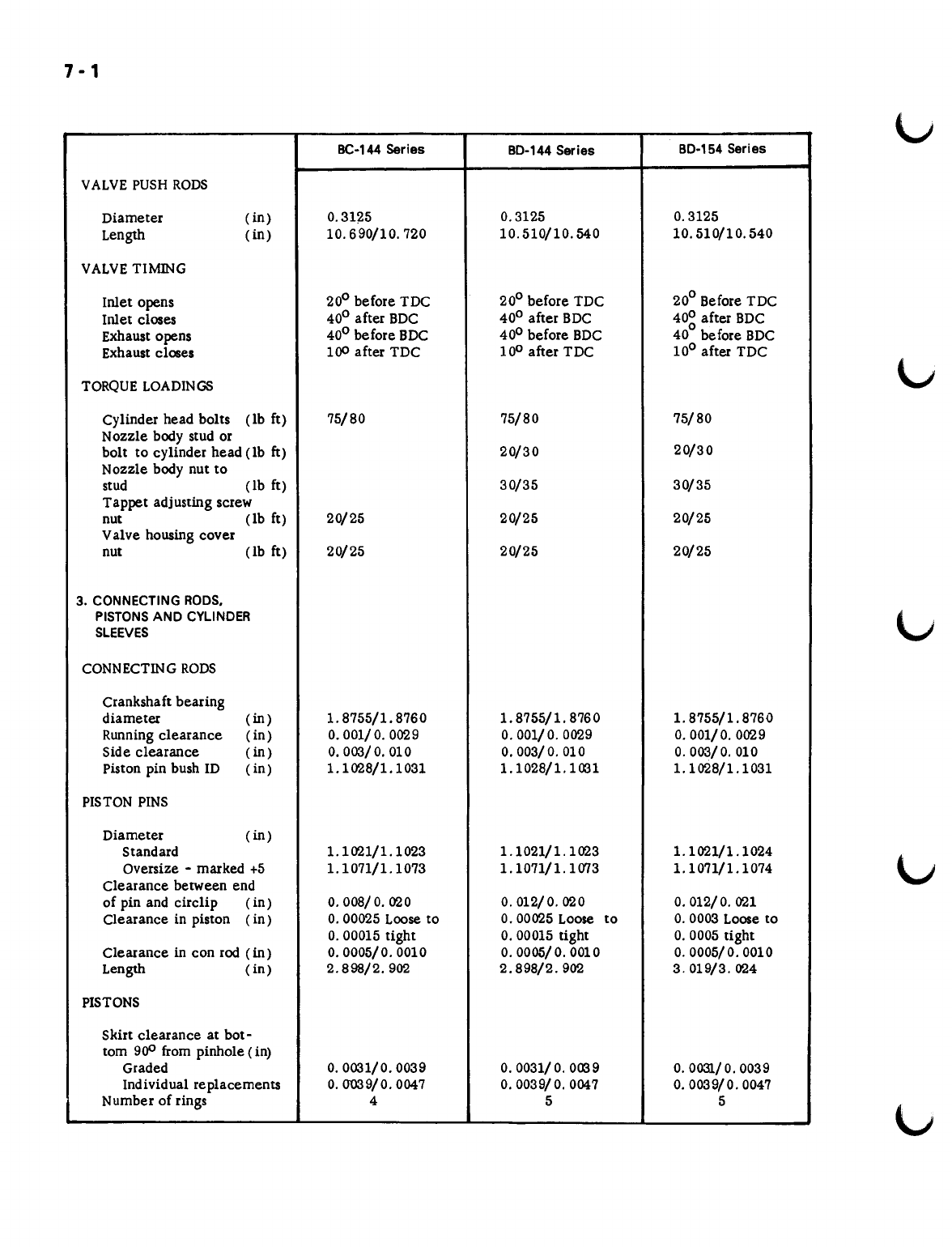
7-1
BC-144 Series 80-144 Series 80-154 Series
VALVEPUSH RODS
Diameter (in)
0.3125 0.3125 0.3125
Length (in)
10.690/10.720 10.510/10.540 10.510/10.540
VALVETIMING
Inlet opens
20
0
before TDC
20
0
before TDC
20
0
Before TDC
Inlet closes
40
0
after BDC
40
0
after BDC
40~
after BDC
Exhaust opens
40
0
before BDC
40
0
before BDC
40
before BDC
Exhaust closes
100
after TDC
10
0
after TDC
10
0
after TDC
TORQUE LOADINGS
Cylinder head bolts (lb ft)
75/80 75/80 75/80
Nozzle body stud or
bolt to cylinder head (Ib
ft)
20/30 20/30
Nozzle body nut to
stud (lb ft)
30/35 30/35
Tappet adjusting screw
nut (lb ft)
20/25 20/25 20/25
Valve housing cover
nut (lb ft)
20/25 20/25 20/25
3. CONNECTINGRODS.
PISTONSAND CYLINDER
SLEEVES
CONNECTING RODS
Crankshaft bearing
diameter (in)
1.8755/1. 8760 1. 8755/1. 8760 1.8755/1. 8760
Running clearance (in)
0.001/ O.0029 O.001/O.0029 O.001/O.0029
Side clearance
(in)
0.003/0.010 0.003/0.010 0.003/0.010
Piston pin bush ID ( in)
1.1028/1.1031 1.1028/1.1031 1.1028/1.1031
PISTON PINS
Diameter
(in)
Standard
1.1021/1.1023 1.1021/1.1023 1.1021/1.1024
Oversize - marked
+5 1. 1071/1. 1073 1.1071/1. 1073 1.1071/1.1074
Clearance between end
of pin and circlip ( in)
O.OOS/0.020 0.012/0.020 O.012/O.021
Clearance in piston ( in)
O.00025
Loose to
0.00025
Loose to
O.0003
Loose to
O.00015
tight
O.00015
tight
O.0005
tight
Clearance in con rod
(in)
0.0005/0.0010
o.
OOOS/0.0010 O.0005/0.0010
Length (in)
2.898/2.902 2.898/2.902 3.019/3.024
PISTONS
Skirt clearance at bot-
tom
900
from pinhole (in)
Graded
0.0031/0.0039 0.0031/0.0039 0.0031/ 0.0039
Individual replacements
0.0"039/0.0047 0.0039/ 0.0047 0.0039/0.0047
Number of rings
455
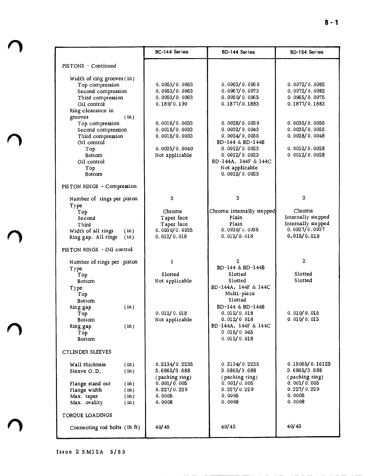
8 - 1
f)
BC-144
Series
BO-144
Series
BO-154
Series
PISTONS- Continued
Width of ring grooves(in)
Top compression 0.0953/0.0963
O.
0963/
O.
0969 0.0972/0.0982
Second compression 0.0953/0.0963 0.0967/ 0.0973 0.0972/0.0982
Third compression 0.0953/0.0963 0.0959/
O.
0965 0.0965/0.0975
Oil control 0.189/ 0.190 0.1877/0.1883 0.1877/0.1883
Ringclearance in
grooves (in)
Top compression
O.
0018/0. 0033 0.0028/0.0039 0.0035/0.0055
Second compression
O.
0018/0. 0033
O.
0032/
O.
0043
O.
0035/0. 0055
Third compression
O.
0018/0.0033
O.
0024/0: 0035 0.0028/0.0048
Oil control BD-144
&
BD-l44B
Top
O.
0025/0. 0040
O.
0012/
O.
0023 0.0012/0.0028
Bottom Not applicable 0.0012/ 0.0023 0.0012/0.0028
Oil control BD-l44A. 144F
&
144C
Top Not applicable
Bottom 0.0012/
O.
0023
PISTONRINGS- Compression
Number of rings per piston 333
Type
Top Chrome Chrome internally stepped Chrome
Second Taper face Plain Internally stepped
Third Taper face Plain Internally stepped
Width of all rings (in) 0.0930/0.0935
O.
0930/0. 0935 0.0927/0.0937
Ring gap. All rings (in) 0.012/
O.
018 0.012/0.018 0.015/0.019
PISTONRINGS- Oil control
Number of rings per piston 122
Type BD-144
&
BD-l44B
Top Slotted Slotted Slotted
Bottom Not applicable Slotted Slotted
Type BD-144A. 144F
&
144C
Top Multi-piece
Bottom Slotted
Ringgap (in) BD-144
&
BD-144B
Top 0.012/
O.
018 0.012/0.018 0.010/0.015
Bottom Not applicable 0.012/0 018 0.010/0.015
Ring gap (in) BD-144A; 144F
&
144C
Top
o
015/ 0.045
Bottom 0.012/ 0.018
CYLINDERSLEEVES
Wall thickness (in) 0.2134/0.2235 0.2134/ 0.2235 0.15065/0.16125
Sleeve O. D. (in) 3.6865/3.688 3.6865/3.688 3 6865/3.688
(packing ring) (packing ring) (packing ring)
Flange stand out (in) 0.001/
O.
005 0.001/0.005
O.
001/
O.
005
Flange width (in) 0.227/ 0.229 0.227/0.229 0.227/ 0.229
Max. taper (in)
O.
0005 0.0005 0.0005
Max. ovality (in) 0.0008 0.0008 0.0008
TORQUELOADINGS
Connecting rod bolts (lb ft) 40/45 40/45 40/45
f)
Issue 2 SM12A 5/69
--------
--
-
.
-

10· 1
n
BC-144Series BO-144Series BO-154Series
6. TIMINGGEARTRAIN.
FRONTCOVERAND
CAMSHAFT
CAMSHAFT
Number of bearings
333
Bearing journal diameter
Front (in)
1.811/1. 812 L811/1. 812 1.811/1. 812
Centre (in)
1.577/ 1. 578 1.577/
l.
578 1.577/1. 578
Rear (in)
1.499/1. 500 1.499/1.500
1.
499/1. 500
Bearing bushing diameter
Front (in)
1.8135/1. 8145 1. 8135/1. 8145 1.8135/1.8145
Centre (in)
1.5795/1.5805
1.
5795/1. 5805 1. 5795/1. 5805
Rear (in)
1.5015/1. 5025 1.5015/1.5025
1.
5015/1. 5025
Running clearance (in)
0.0015/0.0035 0.0015/0.0035 0.0015/0.0035
Exhaust cam lift ( in)
0.1975 0.1975 0.1975
Inlet cam lift
(in)
0.2195 0.2195 0.2195
Max. camshaft lobe
wear (in)
0.020 0.020 0.020
End clearance (in)
O.008/O.017 O.008/O.017 O.008/O.017
Backlash ( in)
0.0025/0.0045 O.0025/O.0045 0.0025/0.0045
TlMING GEARS
Backlash between any
pair of gears ( in)
O.0025/0.0045 0.0025/00045 O.0025/0. 0045
Idler gear end
clearance (in)
0.005/ 0.010 0.005/0.010 0.005/0.010
Idler gear to shaft
clearance (in)
O.0015/0. 0028 0.0015/ 0.0028 0.0015/0.0028
Idler gear lD (in)
3. 0005/3. 0013 3.0005/3.0013 3. 0005/3 .0013
TORQUELOADINGS
Idler gear shaft bolt (lb ft)
75
Min
75
Min
75
Min
Camshaft thrust plate
bolts (lb ft)
35/40 35/40 35/40
Front pulley nut to
crankshaft (lb ft)
225/250 225/250 225/250
Governor gear jam
nut (lb ft)
110/125
7. CRANKSHAFT.MAIN-
BEARINGS
lit
FLYWHEEL
CRANKSHAFT
Number of main bearings
555
Main journal diameter (in)
2.1247/2.1257 2.1247/2.1257 2. 1247/2.1257
Running clearance (in)
O.002/O.005 O.002/O.004 O.002/O.004
Crank pin diameter
(in)
1.7502/1.7507 1. 7502/1. 7507 1.7502/1. 7507
End clearance ( in)
O.004/O.008 0.004/ 0.008 O.004/O.008
MAIN BEARINGS
Reaming dimensions for
replacement bearing
caps (in)
2.2965/2.2975 2.2965/2.2975 2.2965/2.2975
n
n
n
11 - 1
BC-144 Series BO-144 Series BO-154 Series
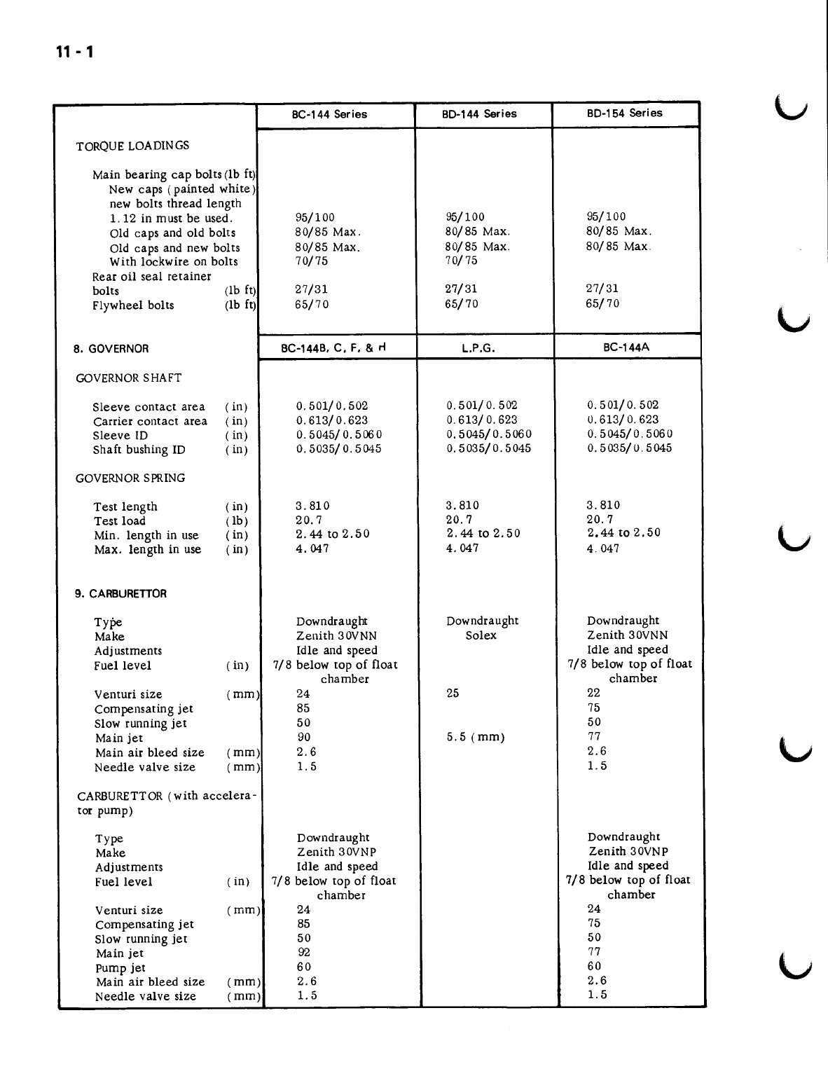
TORQUELOADINGS
Main bearing cap bolts (lb ft)
New caps (painted white)
new bolts thread length
l.12 in must be used. 95/100 95/100 95/100
Old caps and old bolts 80/85 Max. 80/85 Max. 80/85 Max.
Old caps and new bolts 80/85 Max. 80/85 Max. 80/85 Max
With lockwire on bolts 70/75 70/75
Rear oil seal retainer
bolts (lb ft) 27/31 27/31 27/31
Flywheel bolts (lb ft) 65/70 65/70 65/70
8. GOVERNOR BC-144B, C, F, &
rt
L.P.G. BC-144A
GOVERNORSHAFT
Sleeve contact area (in) 0.501/0.502 0.501/ 0.502 0.501/ 0.502
Carrier contact area (in) 0.613/0.623 0.613/
O.
623 0.613/
O.
623
Sleeve ID (in) 0.5045/ 0.506 0 0.5045/0.5060 0.5045/0.5060
Shaft bushing ID (in) 0.5035/ 0.5045 0.5035/0.5045 0.5035/ 0.5045
GOVERNORSPRING
Test length ( in) 3.810 3.810 3.810
Test load (lb) 20.7 20.7 20.7
Min. length in use (in) 2.44 to 2.50 2.44 to 2.50 2.44 to 2.50
Max. length in use (in) 4.047 4.047 4.047
9. CARBURETTOR
Type Downdraught Downdraught Downdraught
Make Zenith 30VNN Solex Zenith 30VNN
Adjustments Idle and speed Idle and speed
Fuel level ( in) 7/8 below top of float 7/8 below top of float
chamber chamber
Venturi size
(rnrn)
24 25 22
compensating jet 85 75
Slow running jet 50 50
Main jet 90 5.5 (mm)
77
Main air bleed size (mm) 2.6 2.6
Needle valve size
(rnm)
1.5 l.5
CARBURETTOR(with accelera-
tor pump)
Type Downdraught Downdraught
Make Zenith 30VNP Zenith 30VNP
Adjustments Idle and speed Idle and speed
Fuel level (in) 7/8 below top of float 7/8 below top of float
chamber chamber
Venturi size (mm) 24 24
Compensating jet 85 75
Slow running jet 50 50
Main jet 92 77
pump jet 60 60
Main air bleed size
(rnrn)
2.6 2.6
Needle valve size (mm) 1.5 l.5

12 - 1
n
BC-144 Series BD-144 Series BD-154 Series
HELl-COIL INSERTS
Depth below surface ( in) 3/32
+
1/32 3/32
+
1/32 3/32 ~ 5/32
Cylinder head - 0 - 0
Idler gear 1/16 ~ 1/32 1/16 -: 1/32 1/16
"!
1/32
SPECIFICATlONS OF VALVEGUIDES AND SPRINGSUSED ON BC-144A ENGINESWHEN EQUIPPEDWITH
DUAL VALVESPRINGS (early models).
VALVEGUIDES
Length (in) 2.625
Inside diameter ( in) 0.344 to 0.345
Set height of guide measured up from
spring recess
I.
in)
1.
047
VALVESPRINGS INLET EXHAUST
INNER OUTER INNER OUTER
-- ----
Test length (ill) 1.258
1.
475
1.
299
1.
516
Test load (lb) 2,1~ 50/0 58 -:
5"/0
22.5 ! 50/0 56 .5!
5
%
Free length (in) 2.125 2.550 2.125 2 550

•
•
•
•
•
INTERNATIONAL
BC-144, BO-144
&
BO-164
SERIES ENGINES
GROUP 2
MANIFOLDS, CYLINDER HEAD
AND VALVES
This manual suits for next models
12
Table of contents


