International Rectifier IRMCS3012 User manual
Datasheet No. PD60316 revA
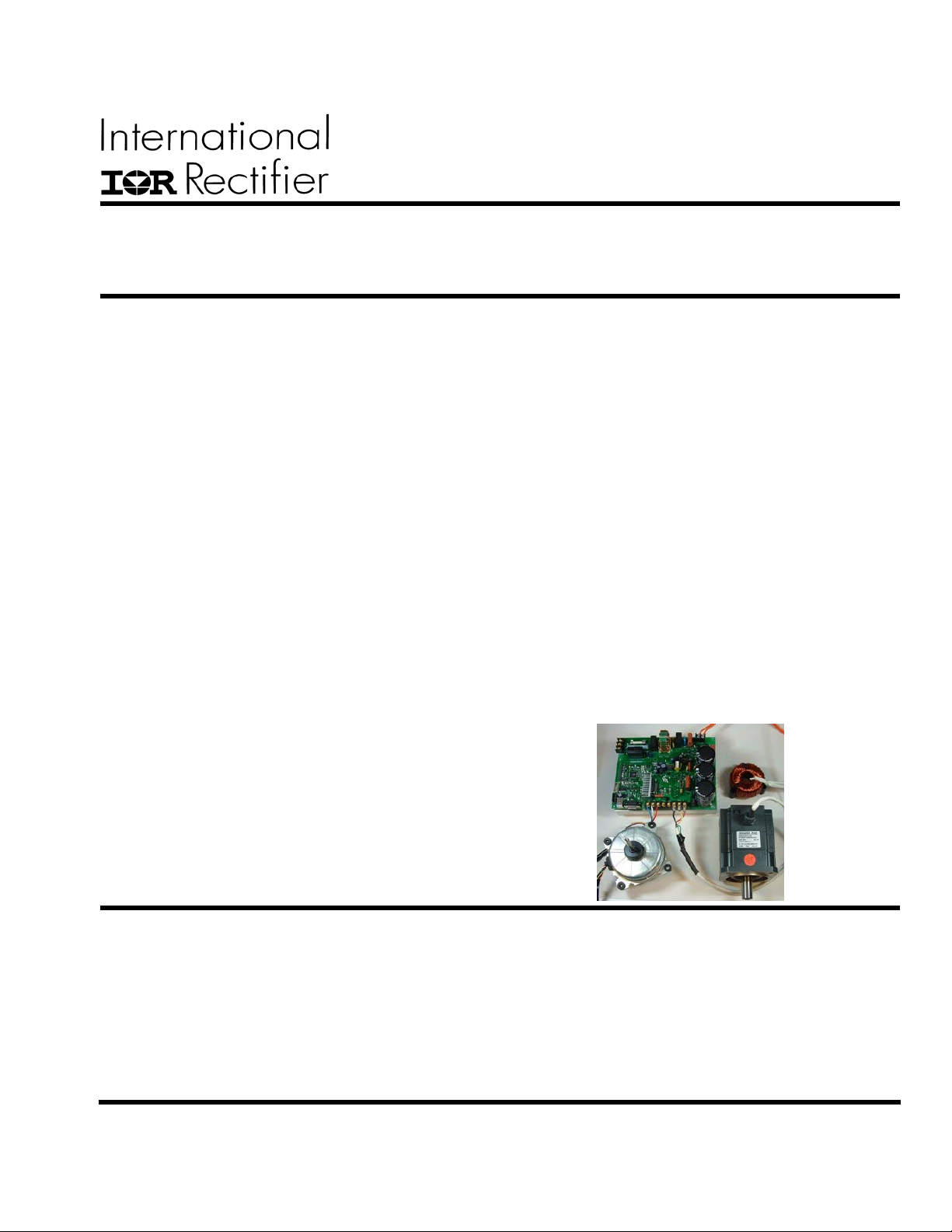
IRMCS3012
Dual Channel Sensorless Motor Drive Platform with Integrated PFC
for Appliance Based on iMOTIONTM Chipset
Features
IRMCF312 - iMOTION
TM
digital control IC - based
system
MCE
TM
(Motion Control Engine) - Hardware based
computation engine for high efficiency sinusoidal
sensorless control of Permanent Magnet motors
Integrated digital power factor correction (PFC)
Supports both interior and surface permanent
magnet motor sensorless control
Single shunt current feedback reconstruction
No external current or voltage sensing OP amp
circuit required
230V/1.8kW continuous power with Trench IGBT
for PFC and Integrated Power Modules for inverter
Harmonic complying EN61000-3-2 Class-A
Dual channel three/two-phase Space Vector PWM
Three-channel analog output (PWM)
Embedded 8-bit high speed microcontroller (8051)
for flexible I/O and man-machine control
JTAG programming port for emulation/debugger
I
2
C serial interface to EEPROM
MCE Designer
TM
tool for easy operation
Flexible drive configuration
RS232C interface
Over-current, over-voltage/under-voltage protection
EMI filter and switch-mode power supply included
Product Summary
Continuous input power 1.8 kW*
Continuous output current 6.0 Arms*
Maximum motor 1 overload output current 20 Apeak**
Maximum motor 2 overload output current 0.9 Apeak**
Maximum Internal clock (SYSCLK) 128 MHz
Sensorless control computation time 11 μsec typ.
RAM loaded from external EEPROM 48 Kbytes
Data RAM 8 Kbytes
A/D input channels 5
A/D converter resolution 12 bits
A/D converter conversion speed 2 μsec
8051 instruction execution speed 2 SYSCLK
Analog output (PWM) resolution 8 bits
RS232C baud rate (typ.) 57.6 Kbps
* Upgradeable to higher current with larger heat sink
** Changeable by modifying the hardware.
Description
IRMCS3012 is a reference design platform for IRMCF312, a high performance RAM-based motion control IC designed
primarily for appliance applications, up to 1.5kW continuous input power. It’s mainly aimed to achieve simple, low cost and
high performance solutions for advanced appliance motor control. It consists of an active PFC frond-end and two inverter
stages, all of which are controlled by the IRMCF312 digital IC simultaneously. The power stage contains a Trench IGBT
(IRGB4063PbF) for the PFC and an integrated power module (IRAMX16UP60A-2) for the first inverter, and another
integrated power module (IRAM336-025SB) for the second inverter, which are part of iMOTION
TM
chipset. Users can readily
evaluate high performance sensorless control with MCEDesigner
TM
software without spending development effort usually
required in the traditional DSP or microcontroller based system. The complete B/Ms, schematics and layout are provided so
that the user can adapt and tailor the design per application needs.
This document is the property of International Rectifier and may not be copied or distributed without expressed consent.

IRMCS3012
This document is the property of International Rectifier and may not be copied or distributed without expressed consent.
2
Table of Contents
1
Introduction ................................................................................................................................................................ 3
1.1
Overview ............................................................................................................................................................. 3
1.2
Safety Precautions ............................................................................................................................................... 4
1.3
Debris When Unpacking ..................................................................................................................................... 6
2
Hardware Description ................................................................................................................................................ 7
2.1
PCB ..................................................................................................................................................................... 8
2.2
Isolation Boundary .............................................................................................................................................. 8
2.3
IRMCF312 .......................................................................................................................................................... 8
2.3.1
Power............................................................................................................................................................ 8
2.3.2
Crystal .......................................................................................................................................................... 8
2.3.3
Reset Circuit ................................................................................................................................................. 8
2.3.4
EEPROM...................................................................................................................................................... 8
2.3.5
Digital I/O..................................................................................................................................................... 8
2.3.6
Analog Output .............................................................................................................................................. 8
2.3.7
Dual Channel Motor Single-Shunt Current Feedback.................................................................................. 8
2.3.8
PFC Current Feedback ................................................................................................................................. 8
2.3.9
AC Input Voltage Feedback ......................................................................................................................... 8
2.3.10
DC Bus Voltage Feedback ......................................................................................................................... 9
2.4
Input Diode Bridge Rectifier............................................................................................................................... 9
2.5
PFC IGBT and Diode.......................................................................................................................................... 9
2.6
PFC Inductor ....................................................................................................................................................... 9
2.7
IRAM .................................................................................................................................................................. 9
2.8
Power Supply ...................................................................................................................................................... 9
2.9
EMI Filter............................................................................................................................................................ 9
2.10
DC Bus Capacitors .......................................................................................................................................... 10
3
Specifications ........................................................................................................................................................... 11
List of Figures
Figure 1. Typical Application Block Diagram Using IRMCF312. ................................................................................ 3
Figure 2. Top View of IRMCS3012. ............................................................................................................................. 7
List of Tables
Table 1. IRMCS3012 Electrical Specification............................................................................................................. 11

IRMCS3012
This document is the property of International Rectifier and may not be copied or distributed without expressed consent.
3
1 Introduction
1.1 Overview
IRMCS3012 is a reference design platform for complete inverter-controlled appliance motor drive applications based
on iMOTION
TM
chipset, up to 1.8kW continuous input power. By using the IRMCF312 digital control IC, it provides
a one-chip solution that simultaneously controls PFC frond-end circuit and two permanent magnetic (PM) AC motors
(sinusoidal back EMF) without requiring motor position sensors.
IRMCF312 is an International Rectifier’s new integrated circuit device primarily designed as a one-chip solution for
sensorless permanent magnet motor control with integrated PFC in appliance applications. Unlike a traditional
microcontroller or DSP, IRMCF312 provides a built-in closed-loop sensorless control algorithm using unique Motion
Control Engine (MCE
TM
) for surface/interior permanent magnet motors with sinusoidal back EMF. IRMCF312 also
employs a unique single shunt current reconstruction circuit to eliminate additional analog/digital circuitry and enables
a direct shunt resistor interface to the IC. The MCE
TM
consists of a collection of control elements, motion peripherals,
a dedicated motion control sequencer, and dual port RAM to map internal signal nodes. Motion control programming
is achieved by using a dedicated graphical compiler integrated into the MATLAB/Simulink
TM
development
environment. Sequencing, user interface, host communication, and upper layer control tasks can be implemented in
the 8051 high-speed 8-bit microcontroller. The 8051 microcontroller is equipped with a JTAG port to facilitate
emulation and debugging tools. Using the MCE
TM
, IRMCF312 also achieves simultaneous digital PFC control of the
front-end circuit that provides a regulated DC bus voltage to the inverter.
Fig 1 shows a typical application block diagram using IRMCF312. In this diagram and in the IRMCS3012 platform,
the PFC topology is implemented as the conventional boost PFC; however, the IRMCF312 IC can also control the
bridgeless PFC topology. Please contact the iMOTION™ team for support if you need to control the bridgeless PFC
using IRMCF312. The IRMCS3012 power stage contains a Trench IGBT (IRGB4063PbF) for the PFC, an integrated
power module (IRAMX16UP60A-2) for the first inverter to drive the compressor motor, and another integrated power
module (IRAM336-025SB) for the second inverter to drive the fan motor. The Trench IGBTs, part of IR’s
iMOTION™ integrated design platform, have lower collector-to-emitter saturation voltage (VCE(ON)) and total
switching energy(ETS) than punch-through (PT) and non-punch-through (NPT) type IGBTs. The combination of low
VCE(ON) and ETS result in reduced power dissipation and higher power density. Both IRAMX16UP60A-2 and
IRAM336-025SB are integrated power modules developed and optimized for appliance motor control.
Passive
EMI
Filter IRMCF312
Galvanic
Isolation
IRS2630D
IPM
DC bus
Communication
to indoor unit
AC input
(100-
230V)
Compressor
Motor
SPM
IRS2631D
60-100 W
Fan Motor
IGBT inverter
FREDFET inveter
EEPROM
7
6
2
User Parameter
Storage
Analog output
Digital I/O
2
1
3
Tem per atur e feedback
Anal og actuator s
Relay, Valves , Swi tches
Motor PWM +
PFC+GF
Fault
EEPROM
User Program
Storage
Anal og i nput
Galvanic
Isolation
Field
Service
Fault
UART
Tem p s ens e
Multple
Power
supply
Motor PWM
15V
3.3V
1.8V
Figure 1. Typical Application Block Diagram Using IRMCF312.

IRMCS3012
This document is the property of International Rectifier and may not be copied or distributed without expressed consent.
4
1.2 Safety Precautions
In addition to the precautions listed throughout this manual, please read and understand the following statements
regarding hazards associated with development system.
ATTENTION:
The ground potential of the IRMCS3012 system is biased to a negative DC
bus voltage potential. When measuring voltage waveform by oscilloscope, the scope ground
needs to be isolated. Failure to do so may result in personal injury or death.
Darkened display LEDs is not an indication that capacitors have discharged to safe voltage
levels.
!
ATTENTION:
IRMCS3012 system contains dc bus capacitors which take time to discharge
after removal of main supply. Before working on drive system, wait three minutes for
capacitors to discharge to safe voltage levels. Failure to do so may result in personal injury or
death.
!
Darkened display LED is not an indication that capacitors have discharged to safe voltage
levels.
ATTENTION:
Only personnel familiar with the drive and associated machinery should plan
or implement the installation, start-up, and subsequent maintenance of the system. Failure to
comply may result in personal injury and/or equipment damage.
!
ATTENTION:
The surface temperatures of the drive may become hot, which may cause
injury.
!

IRMCS3012
This document is the property of International Rectifier and may not be copied or distributed without expressed consent.
5
ATTENTION:
IRMCS3012 system contains ESD (Electrostatic Discharge) sensitive parts
and assemblies. Static control precautions are required when installing, testing, servicing or
repairing this assembly. Component damage may result if ESD control procedures are not
followed. If you are not familiar with static control procedures, reference applicable ESD
protection handbook and guideline.
ATTENTION:
An incorrectly applied or installed drive can result in component damage or
reduction in product life. Wiring or application errors such as undersizing the motor,
supplying an incorrect or inadequate AC supply, or excessive ambient temperatures may result
in system malfunction.
!
!
ATTENTION:
Remove and lock out power from the drive before you disconnect or
reconnect wires or perform service. Wait three minutes after removing power to discharge the
bus voltage. Do not attempt to service the drive until bus voltage has discharged to zero.
Failure to do so may result in bodily injury or death.
!
ATTENTION:
Do not connect power factor correction inductors to drive output terminals U,
V, and W. Failure to do so may result in equipment damage or bodily injury.
!

IRMCS3012
This document is the property of International Rectifier and may not be copied or distributed without expressed consent.
6
1.3 Debris When Unpacking
IRMCS3012 system is shipped with packing materials that need to be removed prior to installation.
!
ATTENTION:
Failure to remove all debris and packing materials which are unnecessary
for system installation may result in overheating or abnormal operating condition.

IRMCS3012
This document is the property of International Rectifier and may not be copied or distributed without expressed consent.
7
2 Hardware Description
A top view of IRMCS3012 is shown in Figure 2.
AC Input
Voltage
Connector
Soft-Start
Resistor and
Relay
Diode Bridge
Rectifier
PFC Inductor
Connector
PFC Current
Sense Shunt
PFC IGBT
Switched-Mode
Power Su
pp
l
y
DC Bus
Capacitors
IRMCF312
Compresso
r IRAM,
Shunt, &
OCP
Fan
IRAM &
Shunt
RS232
Connector
JTAG
Connector
Fan
Motor
Connector
Compressor
Motor
Connector
Digital I/O
EEPROM
Reset Switch
PFC Diode, Gate
Driver and OCP
EMI Filter
Isolation Boundary
DC Bus
Voltage
Connector
Figure 2. Top View of IRMCS3012.
!
WARNING: Except the RS232 and JTAG connectors, all the circuits are directly biased to
the negative DC bus of the power stage, and J6 D/A output and J8 digital I/O connectors are
not isolated from the power ground. If an oscilloscope is needed to make debugging or
measurement ensure it is isolated from the power ground. Otherwise, severe damage will
occur to the PCB and /or equipments.

IRMCS3012
This document is the property of International Rectifier and may not be copied or distributed without expressed consent.
8
2.1 PCB
The PCB has two electrical layers and its size is 6.5 x 8.0 inches.
2.2 Isolation Boundary
Note that there are two different grounds on this system. The RS232 and ITAG connectors are isolated by digital
isolators so that users can connect a computer and FS2 debugger without isolating it. However, users should keep in
mind that most parts of the hardware have negative DC bus ground and it is necessary to isolate the scope when
waveforms are measured.
2.3 IRMCF312
2.3.1 Power
IRMCF312 requires 3.3V and 1.8V. VDD1 is 3.3V used for I/O and VDD2 is 1.8V for digital logic. AVDD is
1.8V for analog and PLLVDD is for PLL. Only one source of 1.8V is shared in the IRMCS3012 system. Typical
current value for 1.8V is less than 100 mA.
2.3.2 Crystal
A 4 MHz crystal is used to generate the system clock. The actual system frequency is adjustable by changing the Phase
Locked Loop configuration through Special Function Registers. For more information regarding clock, please refer to
the IRMCx300 Reference Manual.
2.3.3 Reset Circuit
IRMCF312 doesn’t require external RC circuit for reset. The reset switch is used when the JTAG debugger is
started. For more information regarding reset, please refer to the IRMCx300 Reference Manual.
2.3.4 EEPROM
Boot load takes place at power-up to load 8051 code and MCE code from an external EEPROM to internal RAM of
IRMCF312. EEPROM can be written using the MCEDesigner tool.
2.3.5 Digital I/O
Most of the digital I/O’s are connected to header J8 for the user’s convenience.
2.3.6 Analog Output
Analog D/A output channels are connected to header J6 for ease of use.
2.3.7 Dual Channel Motor Single-Shunt Current Feedback
IRMCF312 contains two Operational Amplifiers for the single shunt-motor current reconstruction circuits, for the
motor 1 (typically compressor motor) and motor 2 (typically fan motor), respectively. Resistors and capacitors for the
amplifier circuits are placed very close to the pins. Note that, to provide better current feedback, there are separate
traces from the shunt resistors instead of sharing a plane with negative DC bus ground.
2.3.8 PFC Current Feedback
IRMCF312 contains an Operational Amplifier for PFC current feedback. The PFC current feedback signal is
obtained through a shunt resistor that is in series with the PFC inductor and located at the negative DC bus side.
Resistors and capacitors for the amplifier circuit are placed very close to the pins. Note that, to provide better current
feedback, there is a separate trace from the shunt resistor instead of sharing a plane with negative DC bus ground.
2.3.9 AC Input Voltage Feedback
IRMCF312 contains an Operational Amplifier for AC input voltage feedback that is mainly used for PFC control. The
AC input voltage signal is obtained through a proprietary differential amplifier circuit and control logic that is
embedded inside of the IRMCF312 IC, together with a few external resistors and capacitors.

IRMCS3012
This document is the property of International Rectifier and may not be copied or distributed without expressed consent.
9
2.3.10 DC Bus Voltage Feedback
The DC bus voltage feedback is used in both motor control and PFC control. This is implemented through a voltage
divider circuit, and the scaled-down analog signal is fed into an ADC input pin (AIN0) of IRMCF312.
2.4 Input Diode Bridge Rectifier
One piece of GBJ2506-F diode bridge rectifier is mounted on a heat sink under the board.
2.5 PFC IGBT and Diode
At the PFC frond-end, one piece of IRGP4063DPbF trench IGBT and one piece of 30ETH06 hyperfast diode are
mounted on the same heat sink under the board. A 15-mΩshunt resistor is in series with the inductor current flowing
path at the negative DC bus side. The voltage across the shunts is used for PFC current feedback and fed to a
comparator of over-current protection circuit. The comparator initiates the over-current shutdown (PGatekill) which
is fed to IRMCF312 IC. The OCP level is about 20A peak. For more information regarding trench IGBTs and
hyperfast diode, please refer to the datasheets.
2.6 PFC Inductor
One piece of PFC inductor is provided separately from the PCB, and should be connected to the J2 connector. The
inductor shown in Figure is 1mH at 15A Idc, with 10Arms current rating. You can use your own inductor for the
evaluation and test. The choice of inductor involves trade-offs in PFC control performance (current ripple,
harmonics and power factor), switching frequency, cost, space, power loss and EMI noise. The default PFC
switching frequency for the IRMCS3012 is set to be 30 kHz, and the typical recommended reasonable inductance
range is about 1mH to 1.5mH. Please note that lower PFC inductance and/or lower switching frequency may cause
higher distortion to the PFC current waveforms, and the system may fail to pass the IEC/EN 61000-3-2 Class A
harmonic regulation.
2.7 IRAM
At the compressor inverter side, one piece of IRAMX16UP60A-2 is mounted on the same heat sink under the board.
There are two 30mΩshunt resistors (in parallel) that are inserted into the negative DC bus and external to the IRAM.
These shunts provide motor current feedback as well as over-current protection. The voltage across the shunts is fed
to a comparator circuit. The comparator initiates the over-current shutdown (CGatekill), and the CGatekill signal is
fed to IRMCF312, and in the meanwhile, it pulls up the IRAM ITRIP pin. The OCP level is changeable by modifying
the hardware. With the default 15-mΩshunt resistance and threshold set up of the comparator, the OCP current is
about 20A peak. For more information regarding IRAM, please refer to IRAM datasheet.
At the fan inverter side, one piece of IRAM336-025SB is used. It has the SIPS package, and is mounted on a separated
small heat sink on top of the board. There is one 500-mΩshunt resistor that is inserted into the negative DC bus and
external to the IRAM. This shunt provides motor current feedback as well as over-current protection. The voltage
across the shunt is fed to the IRAM ITRIP pin. When the ITRIP voltage is higher that the threshold (460mV), the
IRAM is shut down, and its FLT/EN pin is pulled down which makes the FGATEKILL pin of the IRMCF312 IC low.
In addition, there is a comparator circuit that can also make the FGATEKILL pin low when the IRAM is over heated.
The OCP level is changeable by modifying the hardware. With the default 500-mΩshunt resistance, the OCP current
is 0.9A peak. For more information regarding IRAM, please refer to IRAM datasheet.
2.8 Power Supply
The switched-mode power supply (SMPS) operates at about 80 KHz and generates 15V (VCC) and 3.3V. A 1.8V
DC voltage is generated from 3.3V by a linear regulator. All these voltages are biased to the negative DC bus. In
addition, this SMPS also generates an isolated 5V that is used for the RS232 communication and FS2 debugger.
2.9 EMI Filter
The passive EMI filter on the board consists of two 1μF X-caps, two 4.7nF Y-caps and a 1mH common-mode
inductor.

IRMCS3012
This document is the property of International Rectifier and may not be copied or distributed without expressed consent.
10
2.10 DC Bus Capacitors
Three pieces of 470μF, 450V, 85°Celectrolytic capacitors are used as DC bus capacitors.

IRMCS3012
This document is the property of International Rectifier and may not be copied or distributed without expressed consent.
11
3 Specifications
T
C
= 25°C unless specified
Parameters Values Conditions
Input
Voltage and Frequency 220Vrms, +-20% for 50Hz line;
230Vrms, +10%, -15% for 60Hz line
Input current
Watts
7A rms @nominal output
1800W continuous power when
vertically mounted
TA=40°C, RthSA=0.36 °C/W
Vin=230V AC, f
PWM_PFC
=30kHz,
f
PWM_comp
=6kHz, f
O
=60Hz, T
A
=40°C,
RthSA=0.36 °C/W
Input line impedance
Input power factor
Harmonic current
4%∼8% recommended
>99%
Comply with EN61000-3-2 Class-A
Input power < 1800W
Compressor Motor Output
Current 6 Arms nominal, 10 Arms overload RthSA limits ΔTC to 10°C during overload
Host Interface (RS232C)
TXD, RXD 10V Typical 57.6 Kbps, single ended
JTAG interface
TMS, TDI, TCK, TDO 3.3V Interface with FS2 debugger
D/A
8- bit 3 Channel 0-3.3V output 8051 software needs modification to use it.
A/D
12-bit 0-1.2V DC bus voltage, single-shunt dual motor
currents, AC input voltage, AC input current,
AIN1
DC bus voltage
Maximum DC bus voltage 450V
Nominal DC bus voltage 380V Configurable by PFC
PFC Current Feedback
Current sensing device
Resolution
Latency
Comp and Fan Motor Current
Feedback
Shunt resistor
12-bit
1 PWM cycle
Current sensing device Single shunt reconstruction
Resolution 12-bit
Latency 1 PWM cycle
Protection
PFC current trip level
Comp motor current trip level
Fan motor current trip level
20A peak, ±10%
20A peak, ±10%
0.9A peak, ±10%
Detection from shunt on inductor current
return path
Detection from shunt on negative DC bus
Detection from shunt on negative DC bus
Critical over voltage trip 430V Re-scalable
Over voltage trip 410V Re-scalable
Under voltage trip 120V Re-scalable
Power Devices
Trench IGBT for PFC
IRAM for comp inverter
IRAM for fan inverter
IRGP4063DPbF
IRAMX16UP60A-2
IRAM336-025SB
System Environment
Ambient temperature -15 to 43°C 95% RH max. (Non-condensing)
Table 1. IRMCS3012 Electrical Specification

IRMCS3012
This document is the property of International Rectifier and may not be copied or distributed without expressed consent.
12
IR WORLD HEADQUARTERS: 233 Kansas St., El Segundo, California 90245, Tel: (310) 252-7105
http://www.irf.com
Data and specifications subject to change without notice.
Sales Offices, Agents and Distributors in Major Cities Throughout the World.
Table of contents
Other International Rectifier Media Converter manuals


