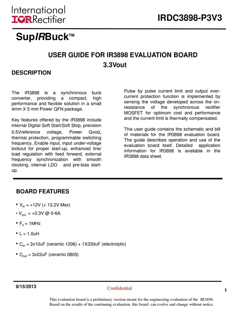
1
www.irf.com
Rev.1.0
Dual_output_2xSO8
6/7/2005
IRDC3621EVAL
SPECIFICATION DATA
INTRODUCTION
IR3621EVALUATIONBOARDUSERGUIDE
Dual output using MOSFETs in SO8 package
INPUT/OUTPUT CONNECTIONS
Thefollowingistheinput/outputconnections:
Inputs:
JP1: Vin and Gnd
JU4:VCCandGnd
JU5:VCL
Outputs:
JP2:Vout1
JP5:Vout2
The connection points for dual output application are
shown in Figure 1. Connect the power supply cables
according to this figure, minimizing wire lengths to re-
duce losses in the wire. Test points J1, J2, J3 and J4
provideeasyconnectionforoscilloscopevoltageprobe
to monitor the inductor points for each PWM section
andoutputvoltages.
ThisreferenceboardisdesignedforDualoutput
configurationand will demonstrate the main features of
IC.
This user guide contains the schematic and bill of
materials,thedesignguidelines are described in data
sheet.
Application Data:
VIN = 12V
VOUT1 = 2.5V
IOUT1 = 10A
VOUT2 = 1.8V
IOUT2 = 10A
∆VOUT = 50mV
FS= 400KHz
Scope Probe connections:
J1andJ3:InductorpointforL2andL3
J2andJ4: Outputsfor Vout1 and Vout2
DESCRIPTION
TheIR3621ICcombines aDual synchronousBuckcon-
troller, providing a cost-effective,high performanceand
flexible solution. The IR3621 can be configured in 2-in-
dependent output or as a 2-phase mode. The 2-phase
configuration is ideal for high current applications. The
IR3621 features 180out of phase operation which re-
ducesthe required input/output capacitance. Other key
featuresoffered by this device include two independent
programmable soft starts, PreBias start up, program-
mable switching frequency up to 500KHz per phase,
external frequency synchronization and under voltage
lockout for proper start up. The current limit is provided
bysensingthe lower MOSFET's on-resistance for opti-
mumcost and performance.
PGOOD:JU1
SYNC:JU2
