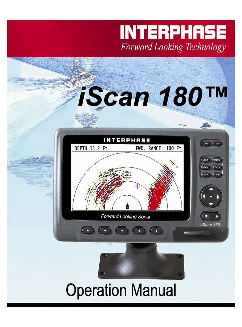
Interphase Sonar Engine SE-200 User manual

1
SE-200
SONAR ENGINE™

2
Thank you for choosing the Interphase
SE-200 Forward Scanning Sonar.
Throughout the development of this
product, we have tried to make sure that
we included all of the suggestions made
by owners of our earlier sonar models.
Selection of features, ease of use, superior
performance and outstanding reliability
were the benchmarks upon which all
important design decisions were made.
We feel proud of the SE-200 and your
satisfaction is very important to us. To
this end, we welcome any comments or
suggestions that you might have in regard
to this equipment.
It is very important that you complete and
return the WARRANTY
REGISTRATION CARD within 15 days
of purchase so that we have a record of
your purchase, both to protect your
warranty and to allow us a method to
contact you about future enhancements,
etc.
To ensure that you receive the maximum
benefits available from the outstanding
features of the Interphase SE-200, please
carefully follow the steps outlined in this
manual. An instructive demonstration
simulator has been designed into the SE-200
and we highly recommend that you spend
some time using the demo mode prior to actual
use of the unit. We also recommend that you
read this entire manual before attempting to
either install or operate your SE-200.
©2007 Interphase Technologies, Inc.
Interphase SE-200 Sonar Engine™ is a trademark of Interphase Technologies, Inc.
Publication # = SE-200
WARNING
Navigation based solely on one method or
one instrument should never be practiced.
While the SE-200 can be quite useful in
showing underwater structure and changing
bottom conditions both below and in front
of your vessel, there are many situations
and conditions which can cause erroneous
or distorted readings.
In addition, there are many situations that
can cause “blind spots” in the SE-200’s
field of view including the presence of
temperature inversion layers (thermoclines),
water turbulence, and high concentrations
of suspended particles in the water.
While the SE-200 can be considered as a
useful aid to navigation, it should never be
the only means of navigation.

3
Table Of Contents
Important Notice 2
SE-200 Overview 4
Getting Started 5
Screen Displays 6
Vertical 6
Horizontal 6
Down / Down Zoom 7
Data 8
Operating Adjustments 9
Range 9
Gain/Screen Cursor 10
Alarm Adjustment 11
Beam Adjustment 12
Display Color Setting 12
Interpreting the Vertical Display 13
Interpreting the Horizontal Display 15
Set-Up 17
Languages/Units 17
More (Max Vert Gain, Boat Icon 17
STC Adjustment 17
Software Setup 18
Keel Offset/ Transducer Level Adjust 18
Demo 19
System Reset 19
Installation 20
Engine Box/ Connecting Transducers 20
Connecting Power/Keypad 21
Connecting Displays 22
Transducer Installation 25
Thru-Hull 26
Transom Mount 29
Inputs & Outputs (NMEA, Alarms) 32
Software Upgrades 33
Accessories (Cables, etc.) 34
Maintenance & Trouble Shooting Tips 35
Interference Problems 35
Specifications 36
Interference Problems 37
Warranty 39

4
SE-200 Overview
The SE-200 Sonar Engine is designed to work with
various multifunction and flat panel displays that have
either composite video or VGA inputs.
The basic system consists of a red colored sonar engine
box (that contains the phased array transmitters and
receivers), a remote keyboard—typically located close
to the display or an Interphase VGA display with
integral keypad, and choice of phased array transducer
(s) which connect directly to the sonar engine box as
shown at left. The remote keypad or the integral
keypad on the Interphase VGA display controls all
system functions including turning the power ON/OFF.
The SE-200 Sonar Engine is capable of working with
different transducers to scan vertically, horizontally and
downward. Interphase offers three basic systems that
come pre-packaged with the red sonar box, remote
keypad, basic video and VGA cables and transducers.
These systems are identified as:
1) SE-200A (With thru-hull or transom mount vertical
scanning transducer. This configuration scans a 90-
degree forward vertical segment and looks down, but
does not scan horizontally).
2) SE-200B (With single thru-hull or two transom
mount transducers. This configuration scans a 90-
degree forward vertical segment, a 90-degree horizontal
segment and looks downward.)
3) SE-200C (With two thru-hull transducers— one for
either side of the vessels keel. This configuration scans
a 90-degree forward vertical segment, a full 180 -
degree forward horizontal segment and also looks
downward.)
Other than different transducers, the installation for any
of these systems is the same, as are the basic features
and operation of the unit. The system software can be
set to operate as either an SE-200A, SE-200B or SE-
200C, depending on which transducer(s) are connected.
TYPICAL SE-200 SONAR
VGA OR VIDEO CABLE
KEYPAD CABLE
KEYPAD
FLAT PANEL VGA OR VIDEO
MULTIFUNCTION DISPLAY
SE-200 SONAR ENGINE
30’
TRANSDUCER(S)
12
VDC
SE-200 SONAR ENGINE
30’
TRANSDUCER(S)
12
VGA CABLE

5
Getting Started
ON/OFF - PWR Button.
Press the red "PWR" button located at the upper right of the
remote keypad (or integral keypad on the Interphase VGA
display) to turn the SE-200 sonar engine box on. The green
LED light on the left end-panel on the red box should light.
To turn the SE-200 sonar engine box off, press and hold down
the PWR button for approximately 3 seconds.
Soft Keys and Screen Menus
The five numbered buttons at the bottom of the remote keypad
(or below the display on the Interphase VGA unit) are called
softkeys (because their use is determined by the menu choices
and the SE-200’ssoftware). Whenever one of the softkey
buttons are pressed, or when making adjustments (like
changing the color mode, brightness, gain or range) a screen
menu will appear at the bottom of the display. For example,
the sketch at right shows the ALARM function being selected.
The remote keypad’s softkeys have numbers just above them
that relate to the numbers on the display menus. When using
the Interphase VGA display, the softkey buttons are directly
below the display menu.
For simplification in this manual, menu choices are shown
with a finger pointing to a menu icon (like the alarm icon at
right). This actually means that the softkey button associated
with this icon is being pushed.
Press the EXIT icon to exit or the menu will disappear after
several seconds..
“NAV” Button
This large button (located at center of keypad) is used to make
adjustments to increase or decrease something - like the
GAIN, RANGE, etc. In several menus you can also use the
softkeys relating to the
symbol that appears in the menu
to make the adjustment.
The
symbols on the NAV button are used to select an
item in the menu. For example, when the GAIN menu is
displayed, the
symbol on the NAV key will select the
DOWN gain to adjust, while pressing the
symbol will select
the SCAN gain to adjust. See RANGE/GAIN on pages 9-10
for details. NAV Button
Row of Softkey buttons on bottom of keypad
or below the Interphase VGA display are
related to the symbols or words at the bottom
of the display.
Depth 13.2 Ft 25 50
25
12.5
Note: Before starting, make sure system software is set to
the proper model (i.e. SE-200A, SE-200B or SE-200C. See
page 18 for details.
EXIT

6
Screen Displays
The SE-200 has four basic display modes which can be
accessed directly by pressing one of the four buttons with
the display’s name. The following paragraphs give a
brief description of each of these display modes. More
detailed information on how to interpret and make
adjustments in these displays can be found in pages 13 to
16 Interpreting your SE-200’s Display.
Vertical Scan
Press the button labeled "VERT" to view a full screen
forward looking vertical scan display. In this mode, the
SE-200 scans a 90 degree sector from the surface ahead
to the bottom directly below. The resulting display shows
the bottom and objects directly in front of the vessel.
The display should look similar to the unit shown at left.
The boat icon at the top left of the display represents the
position of the vessel. The horizontal line with the scale
across the top of the display represents the surface of the
water and the vertical scale represents the depth below the
vessel. The current depth directly below the boat is
shown at the top left of the display - just in front of the
boat icon.
The current forward range is shown by the digital number
at the far top right of the display. This number will
change as different ranges are selected. Adjust RANGE/
GAIN (see pages 9 –10) to optimize the picture.
Horizontal Scan
If your system is an SE-200B or SE-200C (which
includes the horizontal capability), press the button
labeled "HORIZ" to view a full screen forward looking
horizontal scan display. The display should look similar
to the unit shown at left. The boat icon at the bottom
center of the display represents the position of the vessel.
The range rings indicate the forward distance from the
vessel. The current depth directly below the boat is
shown at the top left of the display .
The current forward range is shown by the digital number
at the far top right of the display. This number will
change as different ranges are selected. Adjust RANGE/
GAIN (see pages 9-10) to optimize the picture.
Current Depth Below
Boat
Forward Range
Depth 13.2 Ft 25 50
25
12.5
Depth Scale
Current Depth Below
Boat Forward Range
Targets (Echos)
Position of Boat
25
50
75

7
The Depth Bar on the left side provides a visual
indication of the depth directly beneath the boat.
Down Display (Conventional down
looking)
By pressing the DOWN button - once, the SE-200’s
display will split and a conventional downlooking
display will appear at the left side of the screen as shown
on the right. The downlooking split screen mode will
work in either the vertical or horizontal display modes.
This down looking display is useful as it shows a history
of the bottom depth directly below the boat.
The vertical scale just to the right of the downlooking
display can be used to determine the depth below the
vessel. The current depth is also shown in the large
digits at the top left of the display. Adjust the RANGE
and GAIN for the best picture (see pages 9-10).
To see a full screen downlooking display, press the
DOWN button a second time. The display should look
similar to that shown on the right. This display shows
the recent history of the bottom echos. The most current
information is at the right of the screen.
Note: While in the Forward Horizontal / Down Split
mode, or if you select the Full Screen Down mode while
in the Horizontal mode, the Depth Range can be adjusted
independantly from the Forward Horizontal range.
Changing the Depth Range also changes the range of the
Depth Bar in the Full Screen Forward Horizontal view.
Downlooking Zoom
In the full screen downlooking display, you can ZOOM
into any 25% portion of the depth being displayed. For
example, if the downlooking depth range is 100 feet, then
the ZOOM function can be used to look at any 25% of
the depth - like 10 to 35 feet, 50 to 75 feet, etc.
To turn ON the ZOOM feature, press any of the five
softkeys to bring up the menu shown at right.
Then press the softkey for the ZOOM Symbol to bring
up a split screen zoom picture as shown at bottom right.
The normal depth display is on the left side, while the
larger right portion of the display shows the ZOOMED
picture. The NAV or UP/Down button can be used to
13.2 Ft
25
12.5
Press DOWN Once For Split Screen Downlooking
AND Forward Scanning Display
13.2 Ft
25
12.5
DEPTH
Press DOWN Again For
Full Screen Downlooking Display
NORMAL ZOOM VIDEO ALARM SET-UP
13.2 Ft 18 37
25
12.5
Forward
Range
Depth Below Boat & Conventional
Downlooking Display

8
move the ZOOMED area up or down. The ZOOMED
area is the area between the two horizontal lines on the
normal downlooking display on the left.
Data Display
Press the button labeled DATA and the display will split
to show the current depth, speed* and Lat/Lon
coordinates* in large digits on the left side of the display
(see drawing at left).
*In order for the SE-200 to show the speed, and Lat/Lon
coordinates, the unit must be connected to an NMEA
source of this data - such as an active or “smart” NMEA
speed/temp transducer and/or a GPS (for example, the
Interphase Chart Master Series) or other acceptable
source of NMEA data. Please see NMEA INPUTS on
page 32 for more details.
13.2 Ft
18 37
25
12.5
22.4 KTS
72.6 F
36:52.951 N
121:58.05W
DATA

9
Operating Adjustments
Range/Depth Adjustment
To change the Depth or Forward Range, press the
button labeled RANGE to bring up the Range
Adjustment menu. You can use the up/down NAV
buttons to increase or decrease the range.
The Range adjustment menu in the Vertical and
Horizontal mode is different. In the Horizontal mode,
the forward range and depth can be adjusted
independently, however when in the Vertical mode, the
forward range and depth are related by a fixed ratio of
2:1 (the aspect ration of the display) or, if Depth
Expansion has been selected, a ratio of 4:1.
Therefore, in the vertical mode, changing the forward
range will also change the depth range.
If you are in the hozizontal split screen modes with the
DOWN looking depth showing on the left, you can
adjust the downlooking depth range (Down) and/or
the forward looking scanning range. To adjust the
downlooking depth range, press the left side of the
NAV button to select the DOWN depth adjustment (a
red box will indicate it is selected). To adjust the range
up or down, press the up or down arrow on the NAV
Button.
If the AUTO softkey is pressed, a red box will indicate
the feature is selected and the depth range will
automatically change to track the bottom. Note: when
the unit is in the vertical scan mode, the vertical range
will also change each time the depth range changes,
however when in the horizontal scan mode only the
depth range will change.
The Range menu in the vertical scanning modes also
includes an icon in the middle that resembles a
magnifying glass. Pressing the softkey for this icon
will change the aspect ratio of the screen from 1:2 to
1:4. Use this feature to expand the vertical scale (by a
factor of two) allowing longer forward ranges in
shallow water without the bottom depth being
compressed at the top of the display. A red box around
the icon indicates this feature is selected, pressing the
softkey for this icon again will return the display to the
normal 1:2 aspect ratio.
13.2 Ft 18 37
25
12.5
400100
Use NAV
buttons
to change from Depth to
Forward Range
400100
13.2 Ft 18 37
25
12.5
400
400100
Selecting Auto Depth Ranging
Selecting Depth
Range Expansion

10
When finished, press the EXIT softkey or allow the menu
to time-out after a few seconds.
To adjust the forward looking Range, use the Right side of
the NAV button to select the Forward Range adjustment
(a red box will indicate it is selected). To adjust the range
up or down, use the NAV button.
When finished, press the EXIT softkey or allow the menu
to time-out after a few seconds.
Gain Adjustment (Sentivity)
Press the button labeled GAIN to bring up the choices
available for adjusting the SE-200's receiver GAIN. Press
the button below AUTO so that the word AUTO is shown
inside a red box if you would like the SE-200 to
automatically adjust its receiver gain for changing
conditions. To manually adjust press the on the
NAV button to increase or decrease the receiver gain. Note
that the GAIN MENU shows a number which indicates the
relative gain level being used. When you choose to
manually adjust the GAIN, the SE-200 turns off the
AUTO mode and it will remain off until the AUTO soft
key is again selected. You can also turn off the AUTO
GAIN feature by pressing the AUTO softkey again. To
exit the GAIN MENU and save your adjustments simply
press the exit symbol or allow the menu to time-out
(approx. 6 seconds)
Important Note:One of the biggest problems encountered
with forward scanning sonars is too much gain - especially
in the vertical forward view. If there are no targets
directly in front of the boat, the natural tendency is to
continue to increase the gain which can result in a noisy
display and false targets. In general, if you can see the
bottom between 3 and 4 times the depth forward (for
example in 10 feet of water, seeing the bottom forward 30
to 40 feet) the gain is adequate. (On forward ranges below
200 feet, it’s recommended to keep the gain below the
number 14.)
Screen Cursor
The SE-200 has a useful screen cursor feature that can
show the approximate depth and range from the vessel to
any target on a forward scanning display.
Use Nav Key
to Move Cursor
30 to 40 Ft
10 Ft
Cursor
Bearing: 26
Depth 7.9Ft
Range 45.0Ft
Cursor Data Box
AUTO 31 DOWN AUTO 15 SCAN
Use NAV
buttons to
change from Down to Forward
Scan Gain Adjustment.
13.2 Ft 18 37
25
12.5
31 DOWN AUTO 15 SCAN
AUTO
Selecting AUTO GAIN
for Depth.

11
Pressing the CURSR button will toggle the screen cursor
and it’s CURSOR DATA BOX on and off. The drawing at
right shows a forward horizontal scan display with the
CURSOR activated and the CURSOR DATA BOX in the
lower right corner of the display.
To use the screen Cursor feature, press the CURSR button
to activate and then use the NAV button to move the cursor
to the desired location on the display. Wherever the cursor
is placed, the CURSOR DATA BOX will display the
approximate RANGE, DEPTH and BEARING (if in the
horizontal scanning mode) from the vessel to that location.
It is important to realize that the depth and bearing
information in the CURSOR DATA BOX is the result of a
calculation based on the angle of the acoustic beam below
the surface of the water. Because each transducer
installation is unique and the vessel may be moving up and
down in the water - the angle of the acoustic beam is only
approximately known. Therefore, the calculated depth is
also only an approximation and should not be relied upon
during critical situations.
It is also important to understand that the calculated depth in
the CURSOR DATA BOX is the depth at the center of the
SE-200’s 12-degree acoustic beam angle as shown in the
diagram at right. Notice that the beam expands as it gets
further from the boat. For example, at 1,000 feet the beam
angle has a diameter of greater than 100 feet! However, the
cursor calculates the depth at the centerline of the beam as
shown.
Alarm Adjustment
A forward looking alarm can be set in the downlooking,
vertical and horizontal scan modes. When the alarm is set, a
red “alarm” line and an alarm depth box appears on the
display to indicate the alarm setting and the fact that it is
active.
The actual audio alarm element is located inside the SE-200
Sonar Engine Box. If this unit is mounted far from the dis-
play, it may not be possible to hear the alarm unless an ex-
ternal alarm, such as the Interphase P/N 15-0005-008 Su-
per Beep Piezo Alarm, is connected as shown on the next
page or page 32.
In the vertical scan mode, the alarm will sound if a target
appears above the alarm line. In the horizontal scan mode,
the alarm will sound if a target is closer to the boat than the
alarm line. In additions to the alarm sounding, the alarm box
Range
Surface
Depth
12-Degree
Beam Angle
CURSOR DEPTH AND RANGE
Alarm Setting Targets On This Side of Line Will Cause
Alarm to Sound and Alarm Setting Box to
Blink
Depth 13.2 Ft 25 50
25
12.5
5 Ft
EXIT CLEAR DOWN UP
Bearing: 26
Depth 7.9Ft
Range 45.0Ft
31.5 Ft
Alarm Line
EXIT BEAM COLOR ALARM SET-UP
PRESS ANY SOFTKEY TO BRING UP SOFTKEY MENU

12
will blink to indicate that the alarm has been triggered.
See diagrams at left. To set the alarm, press any of the
five softkeys to bring up the softkey menu. Then, press
the softkey for the ALARM symbol to bring up the
ALARM MENU.
To adjust the alarm setting, use the buttons below the
symbols in the ALARM MENU, or the NAV UP/
DOWN button. Press the softkey button below the
EXIT symbol to save the setting and exit, or press the
button below the CLEAR symbol to disable the
ALARM and exit.
Beam Adjustment
The SE-200 typically scans forward over a 90 degree or
180 degree sector. In some cases you may want to
reduce the size of the sector and scan in a particular
direction. Reducing the sector size is also one way to
increase the scanning speed, as time isn’t wasted by
scanning unwated areas. The BEAM can be adjusted in
both the vertical and horizontal scanning modes.
To adjust the beam, press any of the five softkeys to
bring up the softkey menu and then press the softkey
related to the BEAM symbol to bring up the BEAM
MENU.
Use the NAV buttons to adjust the beam sector size
and then use the NAV left
right buttons to adjust
the resulting sectors direction. Press the EXIT softkey
to save the setting and exit, or press the clear softkey
symbol to disable (reset) the BEAM adjustment and
exit.
A good example of the use of the beam adjustment is
when cruising in deep water where the desired scanning
area is close to the surface (looking for obstructions, etc).
In this situation you could reduce the size of the
scanning sector and then steer it up to the surface. This
would result in the desired coverage but with a much
faster scanning speed. See diagrams at left.
Display Color
Pressing the display color symbol brings up a menu
where you can select from a normal blue background, a
white sunlight visible display or a black nighttime back-
ground. (The up/down brightness controls only work
with the Interphase VGA display.)
Use NAV
Buttons to Steer
Beam Sector
EXIT CLEAR
White (Signal)
Green (+12V)
Peizo
Alarm
SE-200 POWER-I/O CABLE
External Audio Alarm Connection.
(Suggest Interphase P/N 15-0005-008 External
Alarm)
Use NAV
to adjust sector
SELECTING DISPLAY COLOR MODE
Normal Sunlight Night Brightness
(blue screen) (white screen) (black screen) (Only for Interphase)

13
Interpreting The Forward Vertical
Display
The Interphase SE-200 provides a video or VGA display
output which shows acoustic echo returns from the
underwater area beneath and ahead of the vessel. The
Phased Array Transducer typically steers an acoustic beam
over a 90 degree segment. The SE-200 steers the beam to
different positions, transmits a pulse of energy, then waits
a defined period of time (depending on the range selected)
and listens for any return echoes. As the energy from this
acoustic beam strikes underwater objects or the bottom, a
small portion of the energy is reflected as an echo back to
the transducer. When the echo is received at the
transducer, it’s converted into a small electrical signal,
processed and displayed on the display connected to the
SE-200
The unit knows the direction in which it sent the transmit
pulse and the time it took to receive the return echo, so it
can determine the location of the object or bottom that
created the return echo. As the SE-200 sequentially steps
the acoustic beam from directly forward to the bottom, the
display shows a continuously updated display of the return
echoes in their approximate position in relation to the
vessel.
Because the display is only showing the acoustic echoes
that are returned to the transducer, it can not show forward
bottom conditions that are hidden from its field of view or
are hidden due to obstructions in the acoustic beam’s path
through the water. In addition, smooth bottom conditions
far forward of the vessel are difficult to see as very little of
the acoustic energy is reflected back as an echo. See the
sketch at left.
Bottoms that are rough and rocky or are sloping upwards
will reflect more acoustic energy back to the transducer
and will show up better far-forward of the vessel than
bottoms that are very smooth or slope downward.
However, even though the bottom may be smooth and
does not show up far forward, large obstructions (sea wall,
large rocks, underwater shelves, etc.) will typically send
back strong echoes that can be seen far forward, as the
sketch at left indicates.
Strong Return from
Up-sloping Bottom
Weak Return From Far-Forward
Strong Return from Wall Far-Forward

14
Sidelobes
Main Beam
Main Beam
Sidelobe
“False” Bottom
Echoes Caused by
Sidelobe Returns.
Distance Forward
Under typical conditions, the SE-200 will show level or
shallowing bottom contours for a distance forward of
between 4X to 6X the depth below the transducer.
Obstructions in the water, such as walls, mud banks, etc.
may be seen at greater distances, subject to the depth below
the transducer and the 1,200 ft. maximum forward range.
Besides the bottom conditions, water conditions will also
affect the SE-200’s performance. For example, surface
chop, temperature inversion layers (thermoclines) and
muddy water may degrade performance.
Noise and Sensitivity Adjustments
The SE-200 features an AUTO gain feature where it
continuously adjusts the gain to achieve the optimum
picture quality. The gain can also be adjusted manually to
allow for a reduction in gain to minimize the effect of
screen noise, or to increase the gain to show weaker targets.
In the forward scanning modes, the gain setting is
especially important. Too little gain will cause a loss of far
forward readings and too much gain will cause an increase
in screen noise and display unwanted transducer sidelobe
readings.
Transducer Sidelobe Effect
The SE-200’s transducer, like all acoustic transducers, does
not form a perfect beam of acoustic energy. Some of the
acoustic energy is contained in an area called the sidelobes.
In conventional downlooking depthsounders, the sidelobes
create little problem except to distort the size of the actual
beam angle; however, in scanning sonars they can create
echoes that are not placed on the LCD screen in their
proper position (also known as false echoes).
As the SE-200 sends off its acoustic beam in a specific
direction, it assumes that any return echoes are within the
main beam. However, if the sidelobe energy strikes a large
object (i.e. the bottom) and creates a strong return echo, the
SE-200 has no way of knowing that this “false” echo was
not created by the main beam and will go ahead and show it
on the display as if it was located within the main beam.
The most typical display of the sidelobe echoes appears as
an arc at the same distance as the bottom depth, and in the
worst case, from the bottom below to the surface ahead.
After using the SE-200 in different situations, with
different gain settings, you should become proficient in
identifying the bottom echoes caused by the transducer’s
sidelobes. To minimize the sidelobe effect, the gain should
be reduced.
False
Echoes
Transducer

15
Interpreting The Forward
Horizontal Display
In the Horizontal display, the SE-200 scans from left to
right across the boats bow. The forward scanning elements
in the transducer are positioned so that the plane of the
horizontal scan is angled downward approximately 10
degrees from the water’s surface (see sketch at left). This
downward angle is designed to help reduce the effects of
surface noise clutter when the water is choppy and to view
the bottom foward of the boat.
As the acoustic sound beam is projected away from the
boat, the cross-sectional diameter of the beam increases.
At a range of approximately 5 times the depth of the water
the sound beam will begin intersecting the bottom and
some of the sound energy that intersects the bottom will be
reflected back and will appear on the dislay as bottom
echos.
It is important to understand that when the SE-200 is in the
Horizontal display mode, in shallow water - it will
typically show the bottom on the forward display. This
display information can be used to help understand the
structure of the bottom ahead of the boat, but the bottom
echos can also mask or be confused as fish targets.
The center picture and resulting screen display shows a
boat in 14.7 feet of water. The SE-200’s forward range is
set to 100 Ft. Notice that the bottom is just starting to
show at about 75 forward.. A school of fish or bait is
shown about 50 feet to the right and forward of the ship’s
bow.
On the following page, two bottom situations are shown
along with the resulting SE-200 Display.
Noise and Sensitivity Adjustments
The SE-200 features an AUTO gain feature where it
continuously adjusts the gain to achieve the optimum
picture quality. The gain can also be adjusted manually to
allow for a reduction in gain to minimize the effect of
screen noise, or to increase the gain to show weaker
targets.
In the forward scanning modes, the gain setting is
especially important as too little gain will cause a loss of
target detection and too much gain will cause an increase
in screen noise. In the AUTO mode, the SE-200 increases
the forward gain until there is a certain density of targets
Plane of Forward Scan is Angled 10 Degrees Downward From Surface.
Forward beam will reach bottom at approx. 5 times depth
Bait
100 ft Forward Range, Water Depth of 14.7 Ft
Bottom
Echos
Bait Ball

16
Bottom getting shallow to Starboard
Following a Channel
Following a Shoreline or Bank on the display. In most situations the AUTO gain mode
works well, but manual adjustments will often be
required to get the optimum picture - especially when
looking far ahead in shallow water.
Forward Range
Depth
250 500
45
90
Beam Depth at Various Forward Ranges
Beam Depth =
Approx. 0.18 X
Forward Distance
In certain conditions - especially in shallow water -
you may see a horizontal display that shows a target
ahead that remains on the screen at the same
distance - even as the boat moves. This is probably
caused by a transducer sidelobe problem and can be
reduced or eliminated by decreasing the forward
gain.
A sidelobe on the display will show up at a forward
distance equal to the depth - as shown below.
100
50
46.2 Ft
Sidelobe at
same forward
distance as
depth

17
Set-Up
The SE-200’s SET-UP menu allows you to make several
important initial settings. Typically, most of these
settings are only made once and don’t have to be changed.
The keel offset adjustment is a good example. The SET-
UP menu is shown at right and the following paragraphs
describe each choice in detail.
Language/Units
The SE-200 allows the choice of several operating
languages and conversions for distance, speed and
temperature. To select the operating language or choose
the unit conversion to use, press the button labeled
LANGUAGE/UNITS. A display window as shown at
left will pop up on the screen showing the available
languages and unit conversions and the ones which are
currently selected.
Use the softkeys to highlight your desired choice for
language, units for range, temp and speed. When finished
press the EXIT softkey to save your selection and exit this
menu.
More - Max Gain, Choose Boat Icon
Press the softkey below the MORE choice to bring up a
menu to set the MAXIMUM GAIN/range, and boat icon,
or press MORE to adjust the STC to minimize the effect
of surface clutter and select the System Software.
To adjust the MAX VERT GAIN*, use the softkey to
highlight the desired range - then use the NAV (UP/
DOWN) buttons to adjust the Max Gain.
When finished with all settings, press the EXIT symbol to
save your selections and exit the menu.
STC Adjustment
The STC Adjustment can be used to help minimize
surface clutter problems. Typically, most depthsounders
show a band of noise near the surface caused by ringing in
the transducer, surface turbulence in the water and other
factors. Where there is severe surface clutter, the digital
depth display can get confused between showing the true
bottom or the surface clutter. In addition, severe surface
clutter can cause the alarms to sound.
English
French
Spanish
German
Chinese
Korean
Greek
Danish
Ft.
Fa.
M
oF
oC
MPH
Km/Hr
Knots
RANGE SUGGESTED
MAX GAIN
SETTING
0 - 50 Ft 14
0 - 100 Ft 16
0 - 200 Ft 18
0 - 400 Ft 22
0 - 800 Ft 24
0 - 1,200 Ft 31
The SE-200 allows you to customize the maximum possible vertical scan gain
for each range. The table below shows a suggested range of Max Gain settings
that you can set. Too much gain on the shallow ranges will cause excess noise
and false forward targets.
EXIT LANGUAGE TRANSDUCER DEMO MORE
UNITS
FORWARD LOOOKING SONAR ENGINE
90 Horiz Scan &
90 Vertical Scan
Version 1.0
200khz
FT M VERT
MAX GAIN
50 12 14
100 32 16
200 70 14
FA
10
20
40
MORE

18
To minimize these types of problems, the SE-200
includes an STC Adjustment. STC stands for Surface
Time Constant and you can use it to force the SE-200 to
ignore surface clutter. By default, the STC is set to 5
feet - meaning that the digital depth and alarms will
ignore anything closer than 5’ to the transducer. The
clutter will still be displayed, just not used to calculate the
digital depth or sound an alarm.
If you are having problems with the digital depth or
alarms because of excessive surface clutter, you can
increase or decrease the exclusion range as shown at
right.
From the SET-UP menu, choose MORE and from that
menu choose MORE again. Then press the button below
the STC Symbol as shown at right. That will bring up a
display showing the STC adjustment line as shown. Use
the NAV key to adjust up or down to ignore the clutter
area and then press the EXIT symbol to save and return
to a normal display.
After making this adjustment, the surface clutter will still
remain on the display but will be ignored by the alarm
and digital depth functions.
Software Setup
The software in the SE-200 can be configured to act as an
SE-200A, SE-200B or SE-200C, depending on the trans-
ducer(s) installed.
To change the software setup, choose MORE from the
SET-UP menu, then choose MORE again to reach the
Software Setup Page. Push the softkey below the the
Software Setup selections until the desired software is
selected and then press the Exit Softkey. The unit will
then turn off. After 5 seconds turn the unit back on and
go to the SET-UP menu to make sure the SE-200 soft-
ware is correct.
13.2 Ft 18 37
25
12.5
STC
ADJUST-
MENT LINE
SE-200A 90 Vertical
SE-200B 90º Vertical &
90ºHoriz Scan
SE-200C 90º Vertical &
180ºHoriz Scan
SOFTWARE SETUP

19
Transducer Level (L) and
Keel / Depth Offset
On installation the depth displayed is from the transducer.
Normally the transducer is mounted at some distance above
the bottom of the keel. If this distance is entered as a
positive (+) number, (Keel Offset) the display will show
the depth below the keel. The transducer is also mounted
below the water line. If this distance is entered as a
negative (-) number, (Depth Offset) the display will show
depth from the waterline.
The SE-200 also includes an adjustments to compensate for
some transducer installation problems, especially thru-hull
installations, where the transducer’s stem is not perfectly
vertical to the water’s surface. This problem can be caused
by improper installation, or by changes in the boats fore/aft
weight.
When the boat is over a known level bottom, the forward
vertical (VERT) scan display should show a level line. If
the bottom display is slanted upward or downward (as in the
pictures at left), note the approximate angle of the
unwanted upward or downward slope on the display. Then
proceed to the TRANSDUCER adjustment menu, as
above, and press the
softkey buttons to adjust the
Level (L). It is possible to adjust +/- 15 degrees. Positive
numbers will tend to make the bottom slope upwards and
negative numbers will make the bottom slope downwards.
After making the adjustment, go to the forward vertical
display and verify the correction. Once adjusted, the SE-
200’s memory will retain the setting.
Demo
If the DEMO softkey is pressed the SE-200 will go into a
demonstration mode where simulated data is sent to the
display. This mode can be a useful tool to help understand
the operation of the unit. To exit the DEMO mode, press
the DEMO softkey again.
System Reset
The SE-200 remembers most setting when it is turned off.
Normally this is good, however sometimes it can cause
problems and you may want to do a reset on the machine to
restore it to the factory defaults. To do this, turn the unit on
while simultaneously pressing both the CURSR and PWR
buttons.
L= 3.1 Ft
K= +10
K = 0.0
L = 0

20
Installation
Red Sonar Engine Box
The Sonar Engine Box can be mounted in a convenient
location in the engine room, below decks, in a cabinet,
etc. It only needs accessibility for initial installation and
when/if you perform a software upgrade.
1) Select a location where the unit is protected from
excessive temperatures. Heat is one of the worst enemies
of electronic components, and will accelerate component
aging, thereby reducing the trouble-free life of your SE-
200.
2) Mount the SE-200 Sonar Engine box in a location
where it will be convenient to route the power cord and
transducer cable.
Connecting Transducer(s)
The SE-200 red sonar box has a black & white label on
the top. Looking down from the top of the box, there are
three 9-pin transducer connectors on the left end of the
box and several output connectors, a power I/O cable and
LED on the right end.
The sketch at right shows the three 9-pin transducer con-
nectors that are located on the left end panel. The three
connector retaining nuts are different colors which match
the color band on the correct transducer cable.
Notice that the vertical transducer cable always plugs into
the green connector. The SE-200A transducer has a
single vertical scan cable, so the blue and black connec-
tors are not used. The diagrams below at right show the
transducer connections for the various SE-200 configura-
tions.
9 Pin Transducer Cable
Connectors:
(view from front of female
plug)
PIN WIRE WHAT?
1 WHITE 1st Ele
2 Brown 2nd Ele
3 Orange 3rd Ele
4 Yellow 4th Ele
5 Green 5th Ele
6 Blue 6th Ele
7 Violet 7th Ele
8 Gray 8th Ele
9 Shield Ground
MODE
L GREEN
NUT BLUE
NUT BLACK
NUT
SE-200A Vertical N/A N/A
SE-200B Vertical Horizontal N/A
SE-200C Vertical Starboard
Horizontal Port
Horizontal
COLOR
BAND ON
TRANS-
DUCER
CABLE
SE-200A
SE-200C
SE-200B
Starboard
Transducer Port
Transducer
Single Thru-Hull or
Two Transom Mount
Transducers
Transom or
Thru Hull
Transducer
Other manuals for Sonar Engine SE-200
1
Table of contents
Other Interphase Sonar manuals

Interphase
Interphase PC/View User manual

Interphase
Interphase Color Twinscope User manual

Interphase
Interphase iScan V90 User manual

Interphase
Interphase 180 User manual

Interphase
Interphase Outlook User manual

Interphase
Interphase Color Twinscope User manual

Interphase
Interphase PC/180 User manual

Interphase
Interphase Spectra User manual

Interphase
Interphase Proble User manual

Interphase
Interphase PC/180 User manual